2010 NISSAN TIIDA Combination switch
[x] Cancel search: Combination switchPage 3090 of 3745

INTERIOR ROOM LAMPLT-95
< SERVICE INFORMATION >
C
DE
F
G H
I
J
L
M A
B
LT
N
O P
• through 10A fuse (No. 31, located in fuse and fusible link box)
• to key switch and ignition knob switch terminals 2 and 4,
• through 10A fuse [No. 8, located in fuse block (J/B)]
• to BCM terminal 57,
• through 40A fusible link (letter g , located in fuse and fusible link box)
• to BCM terminal 70.
When key is inserted in the key switch and key lock solenoid, power is supplied (without Intelligent Key sys-
tem)
• through key switch and key lock solenoid terminal 1
• to BCM terminal 37.
When key is inserted in the key switch and ignition knob switch, power is supplied (with Intelligent Key system)
• through key switch and ignition knob switch terminal 1
• to BCM terminal 37.
When ignition knob switch is pushed, power is supplied (with Intelligent Key system)
• through key switch and ignition knob switch terminal 3
• to Intelligent Key unit terminal 27.
With the ignition switch in the ON or START position, power is supplied
• through 10A fuse [No. 6, located in fuse block (J/B)]
• to BCM terminal 38.
Ground is supplied
• to BCM terminal 67
• through grounds M57 and M61.
When front door LH is opened, ground is supplied
• to BCM terminal 47
• through front door switch LH terminal 2
• through case ground of front door switch LH.
When front door RH is opened, ground is supplied
• to BCM terminal 12
• through front door switch RH terminal 2
• through case ground of front door switch RH.
When rear door LH is opened, ground is supplied
• to BCM terminal 48
• through rear door switch LH terminal 1
• through case ground of rear door switch LH.
When rear door RH is opened, ground is supplied
• to BCM terminal 13
• through rear door switch RH terminal 1
• through case ground of rear door switch RH.
When back door (hatchback) is opened, ground is supplied
• to BCM terminal 43
• through back door lock assembly (back door switch) terminal 3
• through back door lock assembly (back door switch) terminal 4
• through grounds B117, B132 and D402.
When trunk lid (sedan) is opened, ground is supplied
• to BCM terminal 42
• through trunk lamp switch and trunk release solenoid terminal 3
• through trunk lamp switch and trunk release solenoid terminal 1
• through grounds B117 and B132.
When front door LH is unlocked by front door key cylinder switch LH, the BCM receives a ground signal
• to BCM terminal 7
• through front door key cylinder switch LH terminal 3
• through front door key cylinder switch LH terminal 2
• through grounds M57 and M61.
When a signal, or combination of signals is received by BCM, ground is supplied
• to room lamp terminal 2
• through map lamp terminals 5 and 2 (with map lamp)
• through BCM terminal 63.
With power and ground supplied, the interior room lamp illuminates.
SWITCH OPERATION
When map lamp switch is ON (with map lamp), ground is supplied
• through grounds M57 and M61.
Revision: January 20102010 Versa
Page 3100 of 3745
INTERIOR ROOM LAMPLT-105
< SERVICE INFORMATION >
C
DE
F
G H
I
J
L
M A
B
LT
N
O P
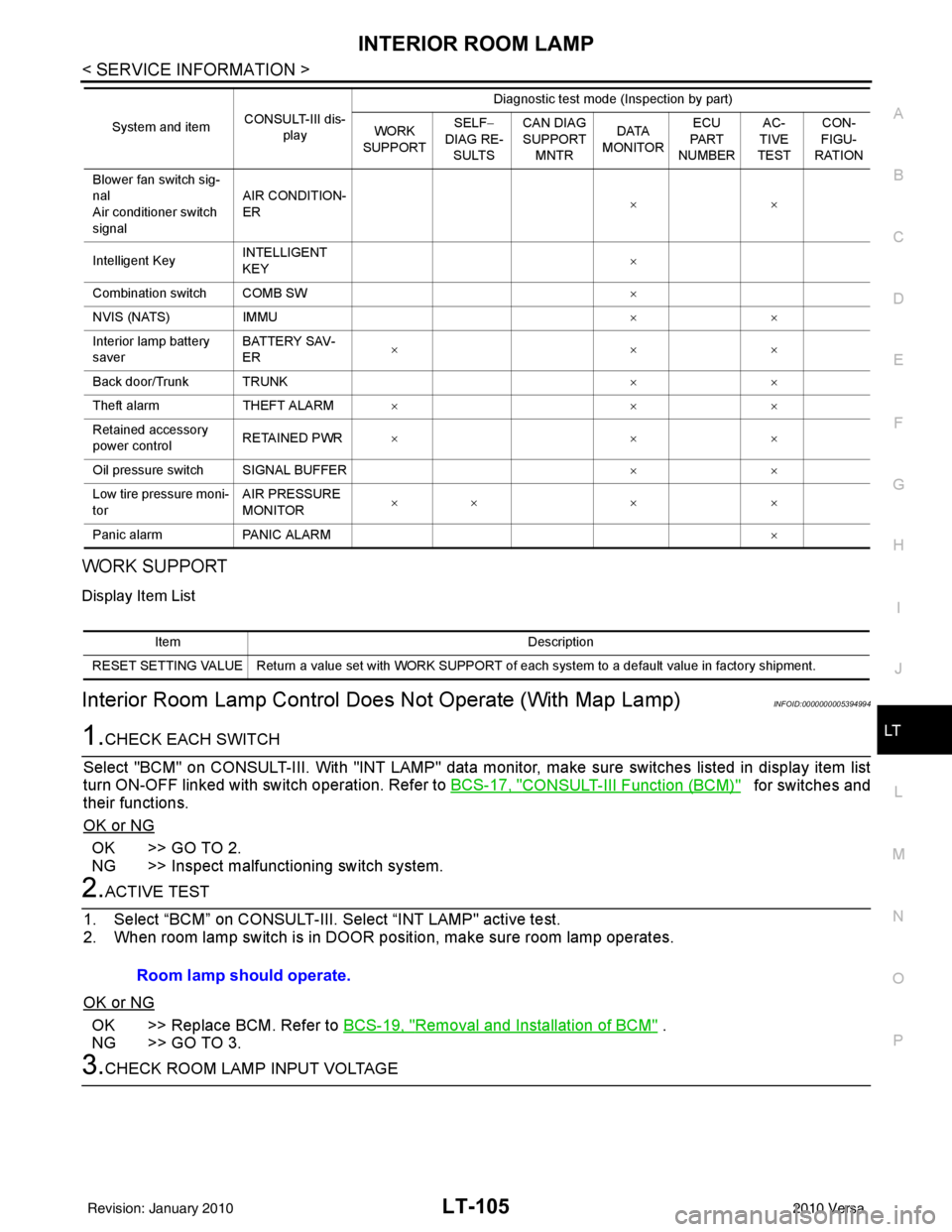
WORK SUPPORT
Display Item List
Interior Room Lamp Control D oes Not Operate (With Map Lamp)INFOID:0000000005394994
1.CHECK EACH SWITCH
Select "BCM" on CONSULT-III. With "I NT LAMP" data monitor, make sure switches listed in display item list
turn ON-OFF linked with switch operation. Refer to BCS-17, "
CONSULT-III Function (BCM)" for switches and
their functions.
OK or NG
OK >> GO TO 2.
NG >> Inspect malfunctioning switch system.
2.ACTIVE TEST
1. Select “BCM” on CONSULT-III. Se lect “INT LAMP" active test.
2. When room lamp switch is in DOOR pos ition, make sure room lamp operates.
OK or NG
OK >> Replace BCM. Refer to BCS-19, "Removal and Installation of BCM" .
NG >> GO TO 3.
3.CHECK ROOM LAMP INPUT VOLTAGE
Blower fan switch sig-
nal
Air conditioner switch
signal AIR CONDITION-
ER
××
Intelligent Key INTELLIGENT
KEY ×
Combination switch COMB SW ×
NVIS (NATS) IMMU ××
Interior lamp battery
saver BATTERY SAV-
ER
××
×
Back door/Trunk TRUNK ××
Theft alarm THEFT ALARM×× ×
Retained accessory
power control RETAINED PWR
×× ×
Oil pressure switch SIGNAL BUFFER ××
Low tire pressure moni-
tor AIR PRESSURE
MONITOR
××
× ×
Panic alarm PANIC ALARM ×
System and item
CONSULT-III dis-
play Diagnostic test mode (Inspection by part)
WORK
SUPPORT SELF
−
DIAG RE-
SULTS CAN DIAG
SUPPORT
MNTR DATA
MONITOR ECU
PA R T
NUMBER AC-
TIVE
TEST CON-
FIGU-
RATION
Item Description
RESET SETTING VALUE Return a value set with WORK SUPPORT of each system to a default value in factory shipment.
Room lamp should operate.
Revision: January 20102010 Versa
Page 3105 of 3745

LT-110
< SERVICE INFORMATION >
ILLUMINATION
ILLUMINATION
System DescriptionINFOID:0000000005394998
The control of the illumination lamps operation is dependent upon the position of the lighting switch. When the
lighting switch is placed in the 1ST or 2ND position, the BCM (body con\
trol module) receives input signal
requesting the illumination lamps to illuminate. This i nput signal is communicated to IPDM E/R (intelligent
power distribution module engine room) across CAN communication lines. CPU (central processing unit)
located in the IPDM E/R controls the tail lamp relay coil. This relay, when energized, directs power to the illu-
mination lamps, which then illuminate.
Power is supplied at all times
• to ignition relay, located in IPDM E/R,
• to tail lamp relay, located in IPDM E/R,
• through 15A fuse (No. 52, located in IPDM E/R) and
• through 20A fuse (No. 53, located in IPDM E/R)
• to CPU located in IPDM E/R,
• through 40A fusible link (letter g, located in fuse and fusible link box)
• to BCM terminal 70, and
• through 10A fuse [No. 8, located in fuse block (J/B)]
• to BCM terminal 57.
With the ignition switch in the ON or START position, power is supplied
• to ignition relay, located in IPDM E/R, and
• through 10A fuse [No. 6, located in fuse block (J/B)]
• to BCM terminal 38.
With the ignition switch in the ACC or ON position, power is supplied
• through 10A fuse [No. 20, located in fuse block (J/B)]
• to BCM terminal 11.
Ground is supplied
• to BCM terminal 67
• through grounds M57 and M61
• to IPDM E/R terminals 39 and 59, and
• through grounds E15 and E24.
ILLUMINATION OPERATION BY LIGHTING SWITCH
With the lighting switch in the 1ST or 2ND position, BCM receives input signal requesting the illumination
lamps to illuminate. This input signal is communica ted to IPDM E/R across CAN communication lines. CPU
located in the IPDM E/R controls the tail lamp relay coil, which, when energized, directs power
• through 10A fuse (No. 37, located in IPDM E/R)
• through IPDM E/R terminal 29
• to illumination control switch terminal 1
• to VDC OFF switch terminal 3 (with VDC)
• to audio unit (with audio unit) or AV control unit (with premium audio system) terminal 9
• to front air control terminal 5
• to A/T shift selector terminal 3 (with 4-speed A/T)
• to CVT shift selector terminal 3 (with CVT)
• to hazard switch terminal 3
• to combination meter terminal 12
• to door mirror remote control switch terminal 16
• to combination switch (spiral cable) terminal 26 (with steering wheel audio control switches)
• to steering wheel audio control switches through combination switch (spiral cable) terminal 18 (with steering wheel audio control switches).
Ground is supplied
• to VDC OFF switch terminal 4 (with VDC)
• to illumination control switch terminal 3, and
• through grounds M57 and M61.
The illumination control switch controls illumination intensity by varying the ground to the following
• through illumination control switch terminal 2
• to audio unit (with audio unit) or AV control unit (with premium audio system) terminal 8
• to front air control terminal 6
• to A/T shift selector terminal 4 (with 4-speed A/T)
• to CVT shift selector terminal 3 (with CVT)
Revision: January 20102010 Versa
Page 3106 of 3745
ILLUMINATIONLT-111
< SERVICE INFORMATION >
C
DE
F
G H
I
J
L
M A
B
LT
N
O P
• to hazard switch terminal 4
• to combination meter terminal 13
• to door mirror remote control switch terminal 15
• to combination switch (spiral cable) terminal 27 (with steering wheel audio control switches)
• to steering wheel audio control switches through combinat ion switch (spiral cable) terminal 21 (with steering
wheel audio control switches).
With power and ground supplied, illumination lamps illuminate.
EXTERIOR LAMP BATTERY SAVER CONTROL
Refer to LT-75, "System Description".
CAN Communication System DescriptionINFOID:0000000005394999
Refer to LAN-7, "System Description" .
Revision: January 20102010 Versa
Page 3301 of 3745

MTC-22
< SERVICE INFORMATION >
TROUBLE DIAGNOSIS
TROUBLE DIAGNOSIS
CONSULT-III Function (BCM)INFOID:0000000005598079
CONSULT-III can display each diagnostic item using the diagnostic test modes shown following.
ITEMS OF EACH PART
NOTE:
CONSULT-III will only display systems the vehicle possesses.
BCM diagnostic
test item Diagnostic mode
Content
Inspection by part WORK SUPPORT
Supports inspections and adjustments. Commands are transmitted to the BCM for
setting the status suitable for required operation, input/output signals are received
from the BCM and received data is displayed.
DATA MONITOR Displays BCM input/output data in real time. ACTIVE TEST Operation of electrical loads can be checked by sending drive signal to them.
SELF-DIAG RESULTS Displays BCM self-diagnosis results. CAN DIAG SUPPORT MNTR The results of transmit/receive diagnosis of CAN communication can be read.
ECU PART NUMBER BCM part number can be read. CONFIGURATION Performs BCM configuration read/write functions.
System and item CONSULT-III dis-
play Diagnostic test mode (Inspection by part)
WORK
SUPPORT SELF
−
DIAG RE-
SULTS CAN DIAG
SUPPORT
MNTR DATA
MONITOR ECU
PA R T
NUMBER AC-
TIVE
TEST CON-
FIGU-
RATION
BCM BCM×× × × ×
Power door lock sys-
tem DOOR LOCK
×× ×
Rear defogger REAR DEFOG-
GER ××
Warning chime BUZZER ××
Room lamp timer INT LAMP ×× ×
Remote keyless entry
system MULTI REMOTE
ENT
××
×
Headlamp HEAD LAMP×× ×
Wiper WIPER×× ×
Turn signal lamp
Hazard lamp FLASHER
××
Blower fan switch sig-
nal
Air conditioner switch
signal AIR CONDITION-
ER
×
Intelligent Key INTELLIGENT
KEY ×
Combination switch COMB SW ×
NVIS (NATS) IMMU ××
Interior lamp battery
saver BATTERY SAV-
ER
××
×
Back door/Trunk TRUNK ××
Theft alarm THEFT ALARM×× ×
Revision: January 20102010 Versa
Page 3405 of 3745
PG-22
< SERVICE INFORMATION >
IPDM E/R (INTELLIGENT POWER DISTRIBUTION MODULE ENGINE ROOM)
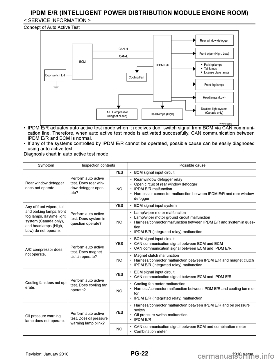
Concept of Auto Active Test
• IPDM E/R actuates auto active test mode when it re ceives door switch signal from BCM via CAN communi-
cation line. Therefore, when auto active test mode is activated successfully, CAN communication between
IPDM E/R and BCM is normal.
• If any of the systems controll ed by IPDM E/R cannot be operated, possible cause can be easily diagnosed
using auto active test.
Diagnosis chart in auto active test mode
WKIA5665E
Symptom Inspection contents Possible cause
Rear window defogger
does not operate. Perform auto active
test. Does rear win-
dow defogger oper-
ate?YES • BCM signal input circuit
NO • Rear window defogger relay
• Open circuit of rear window defogger
•IPDM E/R malfunction
• Harness or connector malfunction between IPDM E/R and rear window
defogger
Any of front wipers, tail
and parking lamps, front
fog lamps, daytime light
system (Canada only),
and headlamps (High,
Low) do not operate. Perform auto active
test. Does system in
question operate?YES • BCM signal input system
NO • Lamp/wiper motor malfunction
• Lamp/wiper motor ground circuit malfunction
• Harness/connector malfunction between IPDM E/R and system in ques-
tion
• IPDM E/R (integrated relay) malfunction
A/C compressor does
not operate. Perform auto active
test. Does magnet
clutch operate?YES
• BCM signal input circuit
• CAN communication signal between BCM and ECM
• CAN communication signal between ECM and IPDM E/R
NO • Magnet clutch malfunction
• Harness/connector malfunction between IPDM E/R and magnet clutch
• IPDM E/R (integrated relay) malfunction
Cooling fan does not op-
erate. Perform auto active
test. Does cooling fan
operate?YES
• ECM signal input circuit
• CAN communication signal between ECM and IPDM E/R
NO • Cooling fan motor malfunction
• Harness/connector malfunction between IPDM E/R and cooling fan mo-
tor
• IPDM E/R (integrated relay) malfunction
Oil pressure warning
lamp does not operate. Perform auto active
test. Does oil pressure
warning lamp blink?YES
• Harness/connector malfunction between IPDM E/R and oil pressure
switch
• Oil pressure switch malfunction
•IPDM E/R
NO • CAN communication signal between BCM and combination meter
• Combination meter
Revision: January 20102010 Versa
Page 3424 of 3745

HARNESSPG-41
< SERVICE INFORMATION >
C
DE
F
G H
I
J
L
M A
B
PG
N
O P
C2 M6 W/4 : Steering lock solenoid D2 M43 W/20 : Audio unit
B3 M7 W/16 : Door mirror re mote control switch D2 M44 W/16 : Audio unit
A3 M8 W/16 : To D2 D2 M45 W/12 : Audio unit
A3 M9 W/16 : To D1 A1 M46 BR/2 : Front tweeter LH
E2 M10 GR/2 : Instrument panel antenna G1 M47 BR/2 : Front tweeter RH
G3 M11 W/4 : To B106 B2 M48 L/4 : Heated mirror relay
G4 M12 W/16 : To B101 E1 M49 W/24 : iPod ® adapter
G3 M13 W/24 : To B102 E1 M50 GR/16 : iPod ® side
G3 M14 W/24 : To B120 E2 M52 W/40 : Intelligent key unit
B4 M15 W/16 : To B23 B2 M53 W/16 : EPS control unit
B4 M16 W/24 : To B24 B3 M54 B/2 : EPS control unit
D5 M17 B/1 : Parking brake switch D2 M55 W/4 : Hazard switch
F2 M18 W/40 : BCM (body control module) B2 M57 — : Body ground
F2 M19 W/15 : BCM (body control module) F2 M59 W/2 : Glove box lamp
F3 M20 B/15 : BCM (body control module)C1 M60 L/2 : EPS control unit
C2 M21 W/4 : NATS antenna amp. F1 M61 — : Body ground
B3 M22 W/16 : Data link connector E2 M62 W/2 : Front blower motor
E3 M23 W/4 : Remote keyless entry receiver C1 M63 W/4 : Torque sensor
C1 M24 W/40 : Combination meter C3 M64 W/8 : Steering angle sensor
C3 M25 /2 : Diode-1 A2 M69 SMJ : To E7
B2 M26 W/6 : Ignition switch D2 M70 W/24 : AV control unit
C2 M27 GR/6 : Key switch and key lock solenoid D2 M71 W/9 : AV control unit
C2 M28 W/16 : Combination switch D1 M72 B/5 : USB interface and aux jack
C3 M29 Y/6 : Combination switch B2 M73 GR/6 : Key switch and ignition knob switch
C3 M30 GR/8 : Combination switch G3 M74 W/12 : To D102
A4 M31 W/24 : To B1 G3 M75 W/12 : To D101
E3 M32 W/4 : To M150 E1 M76 B/4 : USB interface and aux jack
D2 M33 B/15 : Front air control F2 M77 Y/4 : Front passenger air bag module
B3 M34 GR/6 : VDC OFF switch A2 M78 B/2 : To E11
D4 M35 Y/28 : Air bag diagnosis sensor unit B1 M79 — : Body ground
C3 M36 W/3 : Front passenger air bag OFF indicator D3 M150 W/4 : To M32
D4 M38 W/6 : A/T shift selector (with A/T) C3 M151 W/4 : Front blower motor resistor
D4 M38 W/6 : CVT shift selector (without intelligent
key)
Revision: January 20102010 Versa
Page 3426 of 3745
HARNESSPG-43
< SERVICE INFORMATION >
C
DE
F
G H
I
J
L
M A
B
PG
N
O P
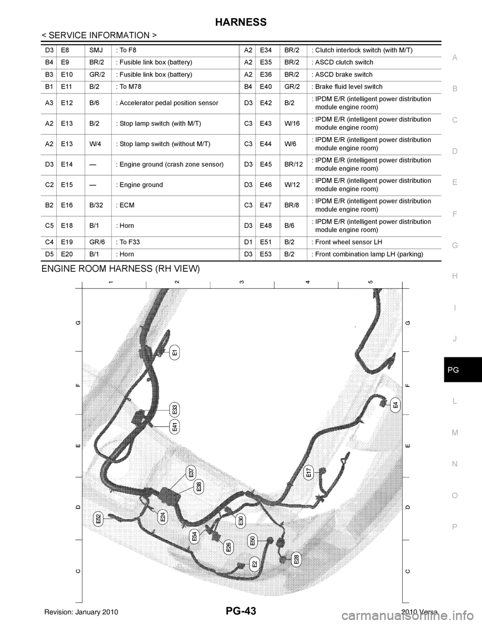
ENGINE ROOM HARNESS (RH VIEW)
D3 E8 SMJ : To F8 A2 E34 BR/2 : Clutch interlock switch (with M/T)
B4 E9 BR/2 : Fusible link box (battery) A2 E35 BR/2 : ASCD clutch switch
B3 E10 GR/2 : Fusible link box (battery) A2 E36 BR/2 : ASCD brake switch
B1 E11 B/2 : To M78 B4 E40 GR/2 : Brake fluid level switch
A3 E12 B/6 : Accelerator pedal position sensor D3 E42 B/2 : IPDM E/R (intelligent power distribution
module engine room)
A2 E13 B/2 : Stop lamp switch (with M/T) C3 E43 W/16: IPDM E/R (intelligent power distribution
module engine room)
A2 E13 W/4 : Stop lamp switch (without M/T) C3 E44 W/6: IPDM E/R (intelligent power distribution
module engine room)
D3 E14 — : Engine ground (crash zone sensor) D3 E45 BR/12 : IPDM E/R (intelligent power distribution
module engine room)
C2 E15 — : Engine ground D3 E46 W/12: IPDM E/R (intelligent power distribution
module engine room)
B2 E16 B/32 : ECM C3 E47 BR/8: IPDM E/R (intelligent power distribution
module engine room)
C5 E18 B/1 : Horn D3 E48 B/6: IPDM E/R (intelligent power distribution
module engine room)
C4 E19 GR/6 : To F33 D1 E51 B/2 : Front wheel sensor LH
D5 E20 B/1 : Horn D3 E53 B/2 : Front combination lamp LH (parking)
Revision: January 20102010 Versa