2010 NISSAN TIIDA oil pressure
[x] Cancel search: oil pressurePage 3010 of 3745

HEADLAMP (FOR USA)LT-15
< SERVICE INFORMATION >
C
DE
F
G H
I
J
L
M A
B
LT
N
O P
x: Applicable
NOTE:
The details for display of the period are as follows:
• CRNT: Error currently detected with IPDM E/R.
• PAST: Error detected in the past and placed in IPDM E/R memory.
DATA MONITOR
All Signals, Main Signals, Selection From Menu
Display items CONSULT-
III display code Malfunction detection TIME
Possible causes
CRNT PAST
NO DTC IS DETECTED.
FURTHER TESTING
MAY BE REQUIRED. ———
——
CAN COMM CIRC U1000 • If CAN communication reception/transmission
data has a malfunction, or if any of the control
units fail, data reception/transmission cannot be
confirmed.
• When the data in CAN communication is not re-
ceived before the specified time. XX
Any of items listed
below have
errors:
• TRANSMIT DIAG
•ECM
• BCM/SEC
IGN RELAY ON —When the ignition switch is not in the ON position,
the ignition relay in the IPDM E/R is ON. XX
Ignition relay (inte-
grated in IPDM E/R)
IGN RELAY OFF —When the ignition switch is not in the ON position,
the ignition relay in the IPDM E/R is OFF. XXIgnition relay (inte-
grated in IPDM E/R)
EEPROM —Malfunction is detected with the integrated EEPROM
memory diagnosis.
X X IPDM E/R
Item nameCONSULT-III
screen display Display or unit Monitor item selection
Description
ALL
SIGNALS MAIN
SIGNALS SELECTION
FROM MENU
Motor fan request MOTOR FAN
REQ1/2/3/4
X X X Signal status input from ECM
Compressor re-
quest AC COMP REQ ON/OFF
X XX Signal status input from ECM
Parking, license,
and tail lamp re-
quest TAIL & CLR REQ ON/OFF
X XX Signal status input from BCM
Headlamp low
beam request HL LO REQ ON/OFF
X XX Signal status input from BCM
Headlamp high
beam request HL HI REQ ON/OFF
X XX Signal status input from BCM
Front fog request FR FOG REQ ON/OFF X XX Signal status input from BCM
FR wiper request FR WIP REQ STOP/1LO/LO/HI X X X Signal status input from BCM
Wiper auto stop WIP AUTO
STOPACT P/STOP P X X
X Output status of IPDM E/R
Wiper protection WIP PROT OFF/LS/HS/Block X X X Control status of IPDM E/R
Starter request ST RLY REQ ON/OFF XX Status of input signal (*1)
Ignition relay
status IGN RLY ON/OFF
X XXIgnition relay status monitored
with IPDM E/R
Rear defogger re-
quest RR DEF REQ ON/OFF
X XX Signal status input from BCM
Oil pressure
switch OIL P SW OPEN/CLOSE X
XSignal status input from IPDM
E/R
Hood switch HOOD SW (*2) OFF XXSignal status input from IPDM
E/R
Revision: January 20102010 Versa
Page 3019 of 3745

LT-24
< SERVICE INFORMATION >
HEADLAMP (FOR USA)
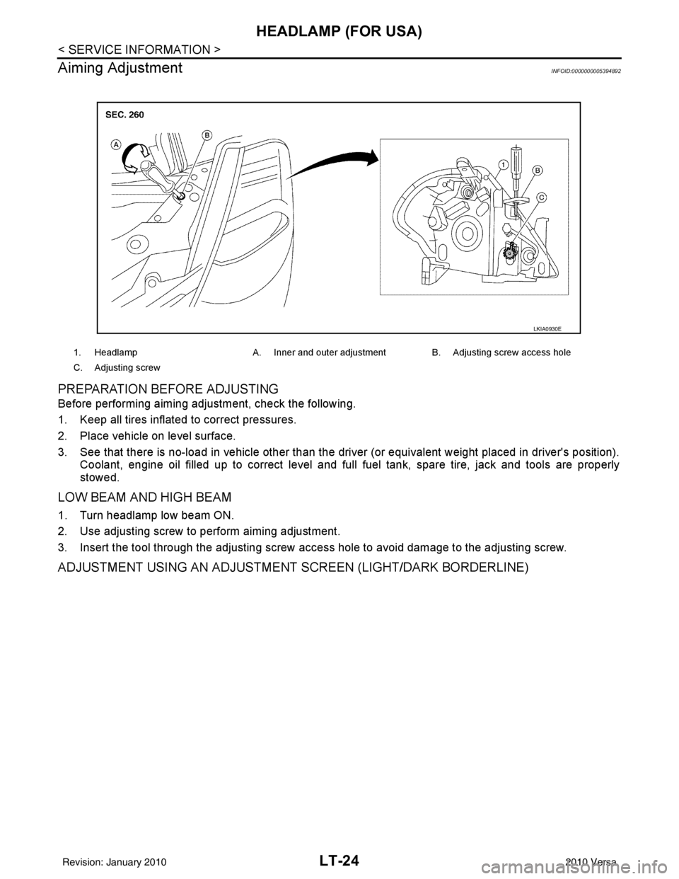
Aiming Adjustment
INFOID:0000000005394892
PREPARATION BEFORE ADJUSTING
Before performing aiming adjustment, check the following.
1. Keep all tires inflated to correct pressures.
2. Place vehicle on level surface.
3. See that there is no-load in vehicle other than the driver (or equivalent weight placed in driver's position). Coolant, engine oil filled up to correct level and full fuel tank, spare tire, jack and tools are properly
stowed.
LOW BEAM AND HIGH BEAM
1. Turn headlamp low beam ON.
2. Use adjusting screw to perform aiming adjustment.
3. Insert the tool through the adjusting screw access hole to avoid damage to the adjusting screw.
ADJUSTMENT USING AN ADJUSTMENT SCREEN (LIGHT/DARK BORDERLINE)
1. Headlamp A. Inner and outer adjustment B. Adjusting screw access hole
C. Adjusting screw
LKIA0930E
Revision: January 20102010 Versa
Page 3033 of 3745

LT-38
< SERVICE INFORMATION >
HEADLAMP (FOR CANADA) - DAYTIME LIGHT SYSTEM -
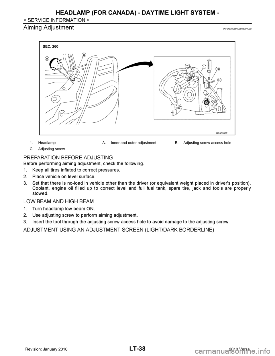
Aiming Adjustment
INFOID:0000000005394908
PREPARATION BEFORE ADJUSTING
Before performing aiming adjustment, check the following.
1. Keep all tires inflated to correct pressures.
2. Place vehicle on level surface.
3. Set that there is no-load in vehicle other than the driv er (or equivalent weight placed in driver's position).
Coolant, engine oil filled up to correct level and full fuel tank, spare tire, jack and tools are properly
stowed.
LOW BEAM AND HIGH BEAM
1. Turn headlamp low beam ON.
2. Use adjusting screw to perform aiming adjustment.
3. Insert the tool through the adjusting screw access hole to avoid damage to the adjusting screw.
ADJUSTMENT USING AN ADJUSTMENT SCREEN (LIGHT/DARK BORDERLINE)
1. Headlamp A. Inner and outer adjustment B. Adjusting screw access hole
C. Adjusting screw
LKIA0930E
Revision: January 20102010 Versa
Page 3044 of 3745

FRONT FOG LAMPLT-49
< SERVICE INFORMATION >
C
DE
F
G H
I
J
L
M A
B
LT
N
O P
1. Check continuity between front fog lamp harness connector and ground.
OK or NG
OK >> Replace IPDM E/R. Refer to PG-28, "Removal and
Installation of IPDM E/R" .
NG >> Repair harness or connector.
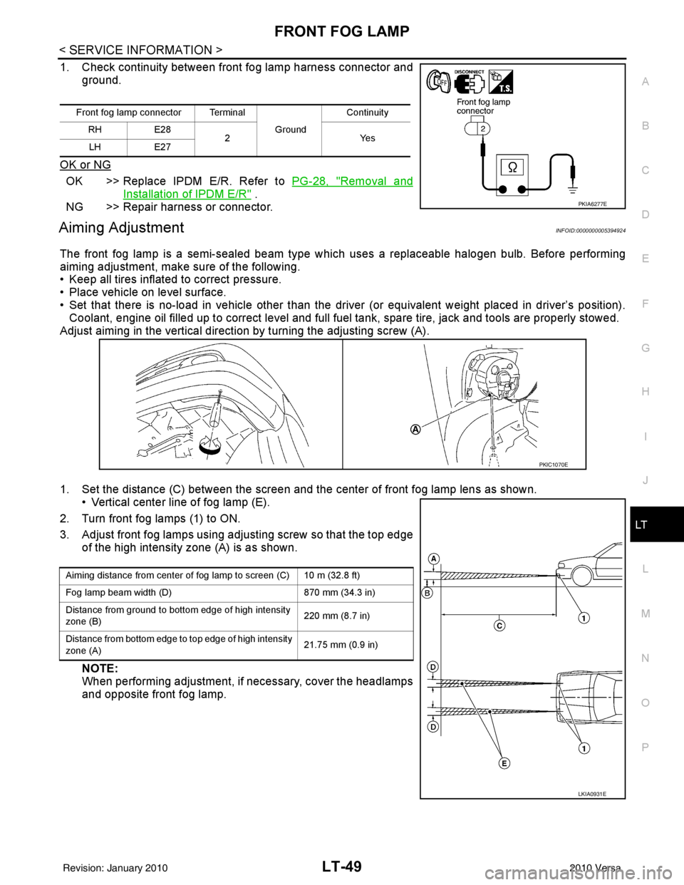
Aiming AdjustmentINFOID:0000000005394924
The front fog lamp is a semi-sealed beam type whic h uses a replaceable halogen bulb. Before performing
aiming adjustment, make sure of the following.
• Keep all tires inflated to correct pressure.
• Place vehicle on level surface.
• Set that there is no-load in vehicle other than the driver (or equivalent weight placed in driver’s position). Coolant, engine oil filled up to correct level and full fuel tank, spare tire, jack and tools are properly stowed.
Adjust aiming in the vertical direction by turning the adjusting screw (A).
1. Set the distance (C) between the screen and the c enter of front fog lamp lens as shown.
• Vertical center line of fog lamp (E).
2. Turn front fog lamps (1) to ON.
3. Adjust front fog lamps using adjusting screw so that the top edge of the high intensity zone (A) is as shown.
NOTE:
When performing adjustment, if necessary, cover the headlamps
and opposite front fog lamp.
Front fog lamp connector Terminal
Ground Continuity
RH E28
2Y es
LH E27
PKIA6277E
PKIC1070E
Aiming distance from center of fog lamp to screen (C) 10 m (32.8 ft)
Fog lamp beam width (D) 870 mm (34.3 in)
Distance from ground to bottom edge of high intensity
zone (B) 220 mm (8.7 in)
Distance from bottom edge to top edge of high intensity
zone (A) 21.75 mm (0.9 in)
LKIA0931E
Revision: January 20102010 Versa
Page 3100 of 3745

INTERIOR ROOM LAMPLT-105
< SERVICE INFORMATION >
C
DE
F
G H
I
J
L
M A
B
LT
N
O P
WORK SUPPORT
Display Item List
Interior Room Lamp Control D oes Not Operate (With Map Lamp)INFOID:0000000005394994
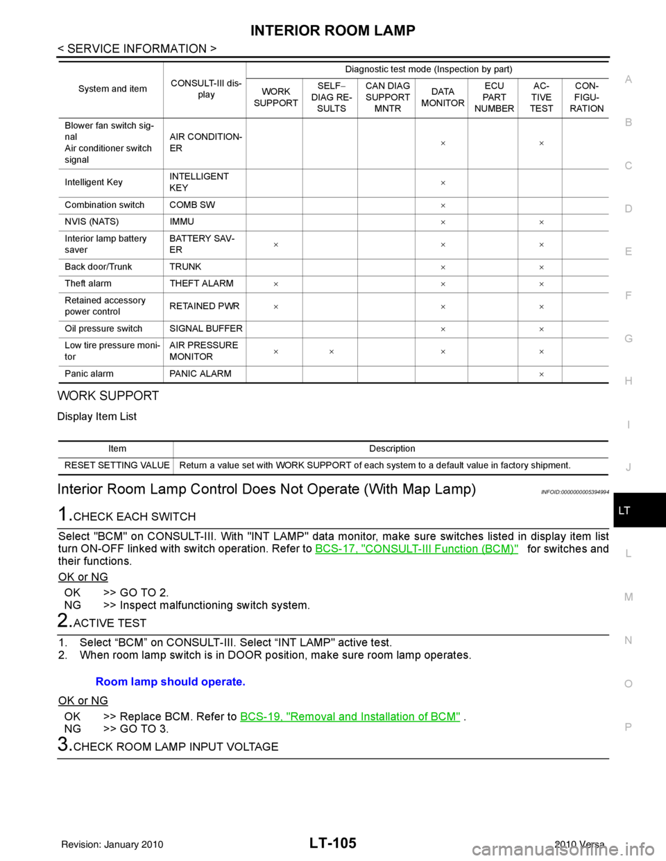
1.CHECK EACH SWITCH
Select "BCM" on CONSULT-III. With "I NT LAMP" data monitor, make sure switches listed in display item list
turn ON-OFF linked with switch operation. Refer to BCS-17, "
CONSULT-III Function (BCM)" for switches and
their functions.
OK or NG
OK >> GO TO 2.
NG >> Inspect malfunctioning switch system.
2.ACTIVE TEST
1. Select “BCM” on CONSULT-III. Se lect “INT LAMP" active test.
2. When room lamp switch is in DOOR pos ition, make sure room lamp operates.
OK or NG
OK >> Replace BCM. Refer to BCS-19, "Removal and Installation of BCM" .
NG >> GO TO 3.
3.CHECK ROOM LAMP INPUT VOLTAGE
Blower fan switch sig-
nal
Air conditioner switch
signal AIR CONDITION-
ER
××
Intelligent Key INTELLIGENT
KEY ×
Combination switch COMB SW ×
NVIS (NATS) IMMU ××
Interior lamp battery
saver BATTERY SAV-
ER
××
×
Back door/Trunk TRUNK ××
Theft alarm THEFT ALARM×× ×
Retained accessory
power control RETAINED PWR
×× ×
Oil pressure switch SIGNAL BUFFER ××
Low tire pressure moni-
tor AIR PRESSURE
MONITOR
××
× ×
Panic alarm PANIC ALARM ×
System and item
CONSULT-III dis-
play Diagnostic test mode (Inspection by part)
WORK
SUPPORT SELF
−
DIAG RE-
SULTS CAN DIAG
SUPPORT
MNTR DATA
MONITOR ECU
PA R T
NUMBER AC-
TIVE
TEST CON-
FIGU-
RATION
Item Description
RESET SETTING VALUE Return a value set with WORK SUPPORT of each system to a default value in factory shipment.
Room lamp should operate.
Revision: January 20102010 Versa
Page 3113 of 3745

LU-1
ENGINE
C
DE
F
G H
I
J
K L
M
SECTION LU
A
LU
N
O P
CONTENTS
ENGINE LUBRICATION SYSTEM
HR16DE
PRECAUTION ....... ........................................
2
PRECAUTIONS .............................................. .....2
Precaution for Supplemental Restraint System
(SRS) "AIR BAG" and "SEAT BELT PRE-TEN-
SIONER" ............................................................. ......
2
Precaution Necessary for Steering Wheel Rota-
tion After Battery Disconnect ............................... ......
2
Precaution for Liquid Gasket .....................................3
PREPARATION ............................................4
PREPARATION .............................................. .....4
Special Service Tool ........................................... ......4
Commercial Service Tool ..........................................4
FUNCTION DIAGNOSIS ...............................6
DESCRIPTION ............................................... .....6
Engine Lubrication System ................................. ......6
Engine Lubrication System Schematic ......................6
ON-VEHICLE MAINTENANCE .....................7
ENGINE OIL ................................................... .....7
Inspection ............................................................ ......7
Draining .....................................................................8
Refilling .....................................................................8
OIL FILTER .........................................................9
Removal and Installation ...........................................9
ON-VEHICLE REPAIR .... .............................10
OIL PUMP ....................................................... ....10
Removal and Installation .........................................10
SERVICE DATA AND SPECIFICATIONS
(SDS) ............... .......................................... ...
11
SERVICE DATA AND SPECIFICATIONS
(SDS) .................................................................
11
Engine Oil Capacity ............................................. ....11
Engine Oil Pressure .................................................11
MR18DE
SERVICE INFORMATION .. .........................
12
PRECAUTIONS .................................................12
Precaution for Supplemental Restraint System
(SRS) "AIR BAG" and "SEAT BELT PRE-TEN-
SIONER" ............................................................. ....
12
Precaution Necessary for Steering Wheel Rota-
tion After Battery Disconnect ...................................
12
Precaution for Liquid Gasket ...................................13
PREPARATION .................................................14
Special Service Tool ................................................14
Commercial Service Tool ........................................14
LUBRICATION SYSTEM ..................................16
Lubrication Circuit ....................................................16
ENGINE OIL ......................................................17
Inspection ................................................................17
Changing Engine Oil ................................................18
OIL FILTER .......................................................20
Removal and Installation .........................................20
OIL PUMP .........................................................21
Component ..............................................................21
Removal and Installation .........................................21
SERVICE DATA AND SPECIFICATIONS
(SDS) .................................................................
23
Standard and Limit ..................................................23
Revision: January 20102010 Versa
Page 3116 of 3745
![NISSAN TIIDA 2010 Service Repair Manual LU-4
< PREPARATION >[HR16DE]
PREPARATION
PREPARATION
PREPARATION
Special Service ToolINFOID:0000000005398153
The actual shapes of Kent-Moore tool
s may differ from those of special service tools illus NISSAN TIIDA 2010 Service Repair Manual LU-4
< PREPARATION >[HR16DE]
PREPARATION
PREPARATION
PREPARATION
Special Service ToolINFOID:0000000005398153
The actual shapes of Kent-Moore tool
s may differ from those of special service tools illus](/manual-img/5/57397/w960_57397-3115.png)
LU-4
< PREPARATION >[HR16DE]
PREPARATION
PREPARATION
PREPARATION
Special Service ToolINFOID:0000000005398153
The actual shapes of Kent-Moore tool
s may differ from those of special service tools illustrated here.
Commercial Service ToolINFOID:0000000005398154
Tool number
(Kent-Moore No.)
Tool name Description
ST25051001
(J-25695-1)
Oil pressure gauge Measuring oil pressure
Maximum measuring range: 2,452 kPa (25
kg/cm
2, 356 psi)
ST25052000
(J-25695-2)
Hose Adapting oil pressure gauge to cylinder block
KV10115801
(J-38956)
Oil filter wrench Removing oil filter
a: 64.3 mm (2.531 in)
WS39930000
(—)
Tube presser Pressing the tube of liquid gasket
NT050
S-NT559
S-NT375
NT052
Revision: January 20102010 Versa
Page 3117 of 3745
![NISSAN TIIDA 2010 Service Repair Manual PREPARATIONLU-5
< PREPARATION > [HR16DE]
C
D
E
F
G H
I
J
K L
M A
LU
NP
O
Tool name
Description
Power tool Loosening nuts and bolts
Deep socket Removing and installing oil pressure switch
a: 26 mm (1.0 NISSAN TIIDA 2010 Service Repair Manual PREPARATIONLU-5
< PREPARATION > [HR16DE]
C
D
E
F
G H
I
J
K L
M A
LU
NP
O
Tool name
Description
Power tool Loosening nuts and bolts
Deep socket Removing and installing oil pressure switch
a: 26 mm (1.0](/manual-img/5/57397/w960_57397-3116.png)
PREPARATIONLU-5
< PREPARATION > [HR16DE]
C
D
E
F
G H
I
J
K L
M A
LU
NP
O
Tool name
Description
Power tool Loosening nuts and bolts
Deep socket Removing and installing oil pressure switch
a: 26 mm (1.02 in)
PBIC0190E
PBIC2072E
Revision: January 20102010 Versa