2010 NISSAN LATIO turn signal
[x] Cancel search: turn signalPage 3505 of 3745

TROUBLE DIAGNOSISRF-21
< FUNCTION DIAGNOSIS >
C
DE
F
G H
J
K L
M A
B
RF
N
O P
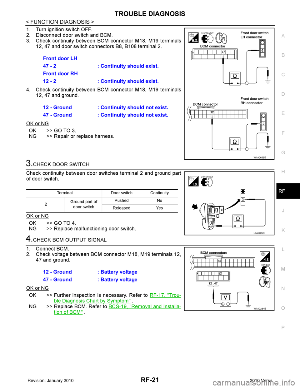
1. Turn ignition switch OFF.
2. Disconnect door switch and BCM.
3. Check continuity between BCM connector M18, M19 terminals 12, 47 and door switch connectors B8, B108 terminal 2.
4. Check continuity between BCM connector M18, M19 terminals 12, 47 and ground.
OK or NG
OK >> GO TO 3.
NG >> Repair or replace harness.
3.CHECK DOOR SWITCH
Check continuity between door switches terminal 2 and ground part
of door switch.
OK or NG
OK >> GO TO 4.
NG >> Replace malfunctioning door switch.
4.CHECK BCM OUTPUT SIGNAL
1. Connect BCM.
2. Check voltage between BCM connector M18, M19 terminals 12, 47 and ground.
OK or NG
OK >> Further inspection is necessary. Refer to RF-17, "Trou-
ble Diagnosis Chart by Symptom" .
NG >> Replace BCM. Refer to BCS-19, "
Removal and Installa-
tion of BCM" .
Front door LH
47 - 2 : Continuity should exist.
Front door RH
12 - 2 : Continuity should exist.
12 - Ground : Continuity should not exist.
47 - Ground : Continuity should not exist.
WIIA0626E
Terminal
Door switch Continuity
2 Ground part of
door switch Pushed
No
Released Yes
LIIA2377E
12 - Ground : Battery voltage
47 - Ground : Battery voltage
WIIA0234E
Revision: January 20102010 Versa
Page 3611 of 3745

SRS-18
< SYMPTOM DIAGNOSIS >
TROUBLE DIAGNOSIS
HOW TO CHANGE BETWEEN SELF-DIAGNOSIS MODE AND USER MODE WITH CONSULT-III
From User Mode to Diagnosis Mode
After selecting “AIR BAG” on the “SELECT SYSTEM” screen, User mode automatically changes to Diagnosis
mode.
From Diagnosis Mode to User Mode
To return to User mode from Diagnosis mode, touch “BACK” key of CONSULT-III until “SELECT SYSTEM”
appears, Diagnosis mode automatically changes to User mode.
HOW TO ERASE SELF-DIAGNOSIS RESULTS
NOTE:
If the memory in “SELF-DIAG [PAST]” is not erased, User mode will continue to show the system mal-
function by the operation of th e warning lamp even if the malfun ction is repaired completely.
• “SELF-DIAG [CURRENT]” A current self-diagnosis result is displayed on the CO NSULT-III screen in real time. After the malfunction is
repaired completely, no malfunction is detected on “SELF-DIAG [CURRENT]”.
• “SELF-DIAG [PAST]” Return to the “SELF-DIAG [CURRENT]” CONSULT-III screen by touching “BACK” key of CONSULT-III and
select “SELF-DIAG [CURRENT]” in SELECT DIAG MODE. Touch “ERASE” in “SELF-DIAG [CURRENT]”
mode.
• “TROUBLE DIAG RECORD”
The memory of “TROUBLE DI AG RECORD” cannot be erased.
Self-Diagnosis Function (Without CONSULT-III)INFOID:0000000005396908
The reading of these results is accomplished using one of two modes —“User mode” and “Diagnosis mode”.
HOW TO CHANGE BETWEEN USER MODE AND SELF-DIAGNOSIS MODE WITHOUT CONSULT-
AIR BAG diagnostic mode Description
SELF-DIAG [CURRENT] A current Self-diagnosis result is displayed on the CO
NSULT-III screen in real time. This refers to a mal-
functioning part requiring replacement.
SELF-DIAG [PAST] Diagnosis results previously stored in the memory are displayed on the CONSULT-III screen. The
stored results will remain until the memory is erased.
TROUBLE DIAG RECORD With TROUBLE DIAG RECORD, diagnosis results previously erased by a reset operation can be dis-
played on the CONSULT-III screen.
ECU DISCRIMINATED NO. Air bag diagnosis sensor unit ECU discriminated number (identification number) is displayed. Air bag
diagnosis sensor unit has individual ECU discriminated number (identification number) based on model
and equipment.
PASSENGER AIR BAG The STATUS (readiness) of the front passenger air bag module is displayed. The STATUS displayed
(ON/OFF) depends on the signals supplied to the occupant classification system control module and
air bag diagnosis sensor unit. Refer to
SRS-6, "
Occupant Classification System (OCS)" for more in-
formation.
Revision: January 20102010 Versa
Page 3630 of 3745

SPIRAL CABLESRS-37
< ON-VEHICLE REPAIR >
C
DE
F
G
I
J
K L
M A
B
SRS
N
O P
SPIRAL CABLE
Removal and InstallationINFOID:0000000005396915
REMOVAL
WARNING:
When servicing the SRS, do not work from directly in front of air bag module.
CAUTION:
• Before servicing the SRS, turn ignition switch OFF, disconnect both battery terminals and wait at
least three minutes.
• Do not tap or bump the steering wheel.
• Do not disassemble the spiral cable.
• Do not allow oil, grease or water to co me in contact with the spiral cable.
• Replace the spiral cable if it has b een dropped or sustained an impact.
• With the steering linkage disconn ected, the spiral cable may snap by turning the steering wheel
beyond the limited number of turns. The spiral cable can be turned counterclockwise about 2.5 turns
from the neutral position.
1. Set the front wheels to the straight-ahead/neutral position.
2. Disconnect the negative and positive battery term inals, then wait at least three minutes.
3. Remove the steering wheel. Refer to PS-6
.
4. Remove the column cover upper and lower.
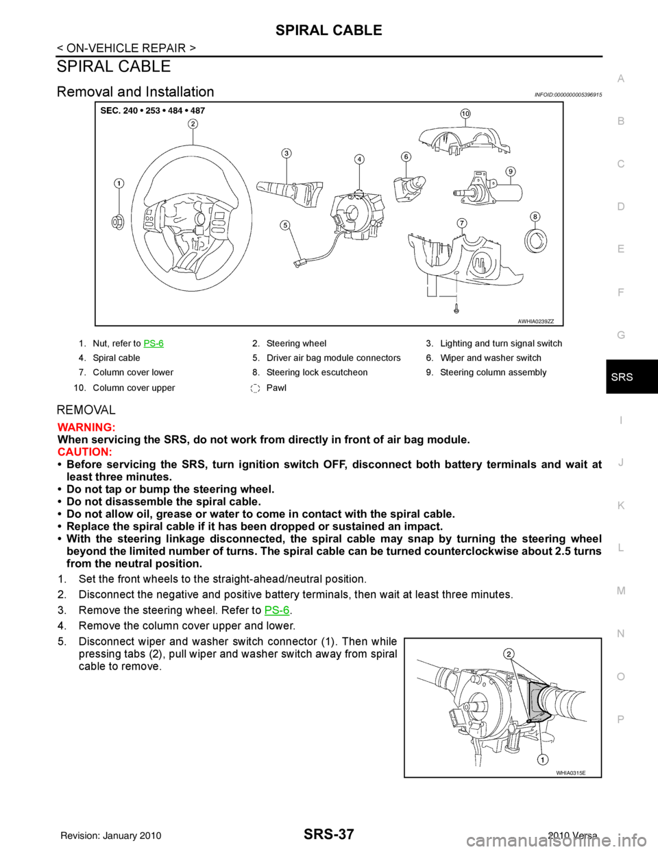
5. Disconnect wiper and washer switch connector (1). Then while pressing tabs (2), pull wiper and washer switch away from spiral
cable to remove.
AWHIA0239ZZ
1. Nut, refer to PS-62. Steering wheel 3. Lighting and turn signal switch
4. Spiral cable 5. Driver air bag module connectors 6. Wiper and washer switch
7. Column cover lower 8. Steering lock escutcheon 9. Steering column assembly
10. Column cover upper Pawl
WHIA0315E
Revision: January 20102010 Versa
Page 3631 of 3745

SRS-38
< ON-VEHICLE REPAIR >
SPIRAL CABLE
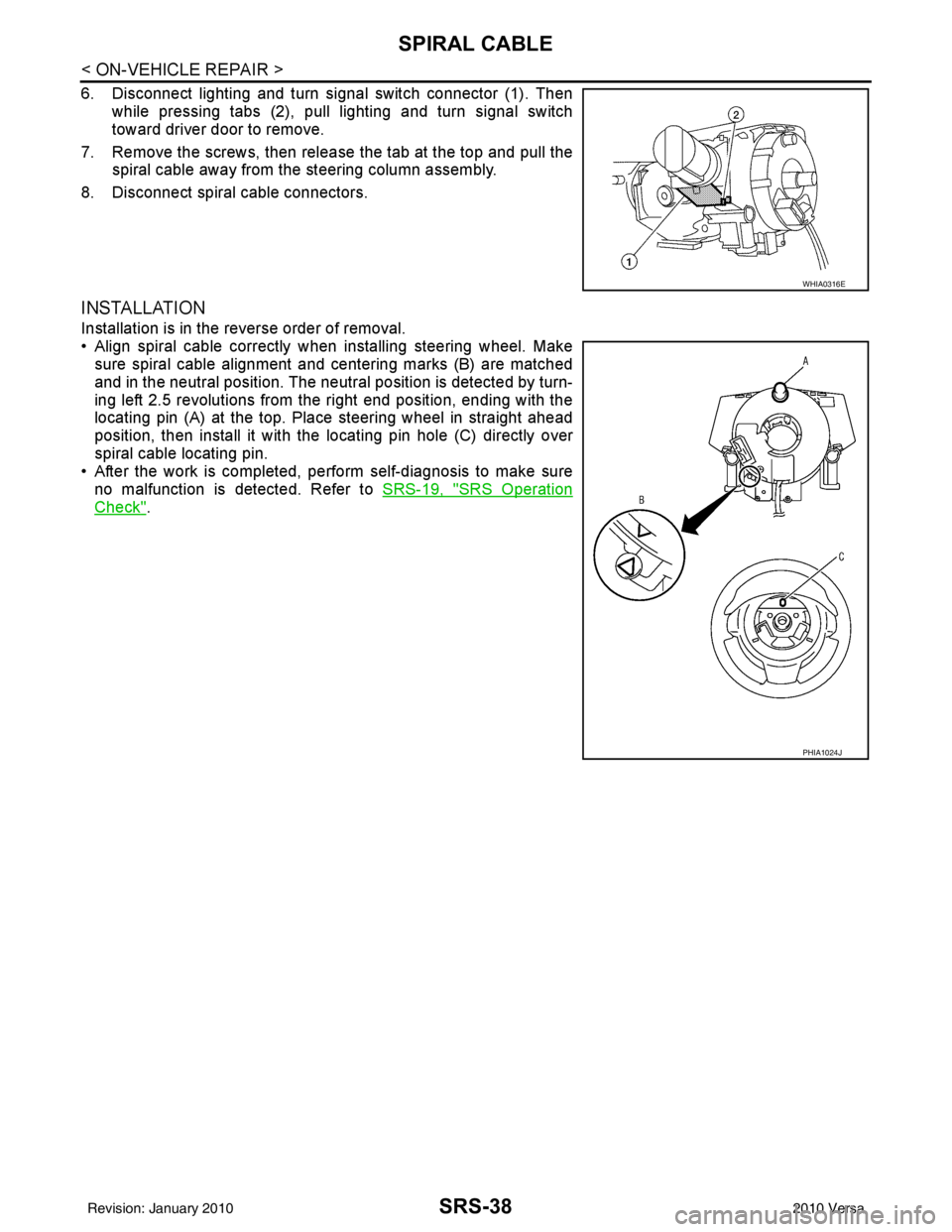
6. Disconnect lighting and turn signal switch connector (1). Thenwhile pressing tabs (2), pull lighting and turn signal switch
toward driver door to remove.
7. Remove the screws, then release the tab at the top and pull the spiral cable away from the steering column assembly.
8. Disconnect spiral cable connectors.
INSTALLATION
Installation is in the reverse order of removal.
• Align spiral cable correctly when installing steering wheel. Make sure spiral cable alignment and centering marks (B) are matched
and in the neutral position. The neutra l position is detected by turn-
ing left 2.5 revolutions from the right end position, ending with the
locating pin (A) at the top. Place steering wheel in straight ahead
position, then install it with the locating pin hole (C) directly over
spiral cable locating pin.
• After the work is completed, perform self-diagnosis to make sure
no malfunction is detected. Refer to SRS-19, "
SRS Operation
Check".
WHIA0316E
PHIA1024J
Revision: January 20102010 Versa
Page 3647 of 3745

STC-1
STEERING
C
DE
F
H I
J
K L
M
SECTION STC
A
B
STC
N
O P
CONTENTS
STEERING CONTROL SYSTEM
EPS
BASIC INSPECTION ....... .............................
3
DIAGNOSIS AND REPAIR WORKFLOW ..... .....3
Work Flow ........................................................... ......3
SYSTEM DESCRIPTION ..............................5
EPS SYSTEM ... .............................................. .....5
System Diagram .................................................. ......5
System Description ...................................................5
Component Parts Location ........................................6
Component Description .............................................6
DIAGNOSIS SYSTEM (EPS CONTROL UNIT)
.....
8
CONSULT-III Function ........................................ ......8
DTC/CIRCUIT DIAGNOSIS ..........................9
C1601 BATTERY POWER SUPPLY ..................9
Description .......................................................... ......9
DTC Logic .................................................................9
Diagnosis Procedure .................................................9
C1604 TORQUE SENSOR .................................11
Description ..............................................................11
DTC Logic ...............................................................11
Diagnosis Procedure ...............................................11
C1606 EPS MOTOR ...........................................13
Description .......................................................... ....13
DTC Logic ...............................................................13
Diagnosis Procedure ...............................................13
Component Inspection ............................................13
C1607, C1608 EPS CONTROL UNIT ................15
Description .......................................................... ....15
DTC Logic ...............................................................15
Diagnosis Procedure ...............................................15
C1609 VEHICLE SPEED SIGNAL .....................16
Description ........................................................... ....16
DTC Logic ................................................................16
Diagnosis Procedure ...............................................16
C1610 ENGINE STATUS SIGNAL ...................17
Description ...............................................................17
DTC Logic ................................................................17
Diagnosis Procedure ...............................................17
U1000 CAN COMM CIRCUIT ...........................18
Description ...............................................................18
DTC Logic ................................................................18
Diagnosis Procedure ...............................................18
EPS WARNING LAMP ......................................19
Description ...............................................................19
Component Function Check ....................................19
Diagnosis Procedure ...............................................19
ECU DIAGNOSIS INFORMATION ..............20
EPS CONTROL UNIT .......................................20
Reference Value .................................................. ....20
Wiring Diagram - ELECTRONICALLY CON-
TROLLED POWER STEERING SYSTEM - ............
22
Fail-Safe .............................................................. ....23
DTC Inspection Priority Chart ..................................24
DTC Index ...............................................................24
SYMPTOM DIAGNOSIS ..............................25
EPS WARNING LAMP DOES NOT TURN ON ...25
Description ........................................................... ....25
Diagnosis Procedure ...............................................25
EPS WARNING LAMP DOES NOT TURN
OFF ....................................................................
26
Description ...............................................................26
Diagnosis Procedure ...............................................26
STEERING WHEEL TURNING FORCE IS
HEAVY OR LIGHT ............................................
27
Revision: January 20102010 Versa
Page 3651 of 3745
![NISSAN LATIO 2010 Service Repair Manual EPS SYSTEMSTC-5
< SYSTEM DESCRIPTION > [EPS]
C
D
E
F
H I
J
K L
M A
B
STC
N
O P
SYSTEM DESCRIPTION
EPS SYSTEM
System DiagramINFOID:0000000005600156
System DescriptionINFOID:0000000005600157
• EPS con NISSAN LATIO 2010 Service Repair Manual EPS SYSTEMSTC-5
< SYSTEM DESCRIPTION > [EPS]
C
D
E
F
H I
J
K L
M A
B
STC
N
O P
SYSTEM DESCRIPTION
EPS SYSTEM
System DiagramINFOID:0000000005600156
System DescriptionINFOID:0000000005600157
• EPS con](/manual-img/5/57358/w960_57358-3650.png)
EPS SYSTEMSTC-5
< SYSTEM DESCRIPTION > [EPS]
C
D
E
F
H I
J
K L
M A
B
STC
N
O P
SYSTEM DESCRIPTION
EPS SYSTEM
System DiagramINFOID:0000000005600156
System DescriptionINFOID:0000000005600157
• EPS control unit performs an arithmetical operation on data, such as steering wheel turning force (sensor
signal) from the torque sensor, vehicle speed signal, etc. Then it generates an optimum assist torque signal
to the EPS motor according to the driving condition.
• EPS control unit decreases the output signal to EPS mo tor while extremely using the power steering func-
tion (e.g., full steering) consecutively for protec ting EPS motor and EPS control unit (Overload protection
control). While activating overload protection control, the assist torque gradually decreases, and the steering
wheel turning force becomes heavy. The normal assist torque reactivates by no steering.
• In case of an error in the electrical system, the fail- safe function stops output signals to the EPS motor. Then
the previous state is changed to the manual steering state.
• Self-diagnosis can be done with CONSULT-III.
• EPS control unit will decrease assistance under the following 2 conditions.
- Extensive steering at low speed will cause the ECU and MOTOR to heat up, once temperature reaches crit-
ical point ECU will reduce current to reduce heat up. System will recover as temperature lowers (reduced or
no assistance).
- Holding steering on rack-end (full lock) for 1 second will cause the system to engage rack-end protection. This reduces assistance down to 50% in order to prevent heat up. Assistance is immediately returned to
100% when steering released or turned away from rack-end.
- Communicates the signal from each control unit via CAN communication.
WGIA0187E
Control unit Signal status
ECM Transmits mainly the follow
ing signals to EPS control uni t via CAN communication.
Engine status signal
ABS actuator and electric unit
(control unit) Transmits mainly the follow
ing signals to EPS control uni t via CAN communication.
Vehicle speed signal
Revision: January 20102010 Versa
Page 3654 of 3745
![NISSAN LATIO 2010 Service Repair Manual STC-8
< SYSTEM DESCRIPTION >[EPS]
DIAGNOSIS SYSTEM (EPS CONTROL UNIT)
DIAGNOSIS SYSTEM
(EPS CONTROL UNIT)
CONSULT-III FunctionINFOID:0000000005600160
FUNCTION
CONSULT-III can display each diagnostic NISSAN LATIO 2010 Service Repair Manual STC-8
< SYSTEM DESCRIPTION >[EPS]
DIAGNOSIS SYSTEM (EPS CONTROL UNIT)
DIAGNOSIS SYSTEM
(EPS CONTROL UNIT)
CONSULT-III FunctionINFOID:0000000005600160
FUNCTION
CONSULT-III can display each diagnostic](/manual-img/5/57358/w960_57358-3653.png)
STC-8
< SYSTEM DESCRIPTION >[EPS]
DIAGNOSIS SYSTEM (EPS CONTROL UNIT)
DIAGNOSIS SYSTEM
(EPS CONTROL UNIT)
CONSULT-III FunctionINFOID:0000000005600160
FUNCTION
CONSULT-III can display each diagnostic item us ing the diagnostic test modes shown following.
ECU IDENTIFICATION
Displays the part number stored in the control unit.
SELF-DIAG RESULTS MODE
Display Item List
Refer to STC-24, "DTC Index".
CAUTION:
If “CAN COMM CIRCUIT [U1000]” is disp layed with other DTCs, first perform the trouble diagnosis for
CAN communication line.
DATA MONITOR MODE
Display Item List
*1: Almost in accordance with the value of MOTOR SIG. It is not a malfunction though these values are not accorded when steerin g
quickly.
*2: It is not a malfunction, though it might not be corresponding just after ignition switch in turned ON. Diagnostic test mode
Function
ECU identification Steering column assembly number can be read.
Self diagnostic result Self-diagnostic results can be read and erased quickly.
Data monitor Input/Output data in the EPS control unit can be read.
Monitor item (Unit) Remarks
MOTOR VOL (V) Displays the power supply voltage for EPS control unit.
TORQUE SENSOR (Nm) Displays steering wheel turning force detected by torque sensor.
MOTOR CURRENT (A) Displays the current value consumed by EPS motor.
MOTOR SIG (A)
*1Displays the current commanded value to EPS motor.
DERATING STAT (ON/OFF%) Protect overload status is displayed.
VEHICLE SPEED (km/h) or (MPH)
*2Vehicle speed is displayed from vehicle speed signal via CAN communication.
WARNING LAMP (On/Off) EPS warning lamp control status is displayed.
ENGINE STATUS (Stop/Run) Engine speed is displayed from engine status signal via CAN communication.
Revision: January 20102010 Versa
Page 3656 of 3745
![NISSAN LATIO 2010 Service Repair Manual STC-10
< DTC/CIRCUIT DIAGNOSIS >[EPS]
C1601 BATTERY POWER SUPPLY
Is the inspection result normal?
YES >> GO TO 3.
NO >> Check the following. If any items are damaged, repair or replace damaged parts.
NISSAN LATIO 2010 Service Repair Manual STC-10
< DTC/CIRCUIT DIAGNOSIS >[EPS]
C1601 BATTERY POWER SUPPLY
Is the inspection result normal?
YES >> GO TO 3.
NO >> Check the following. If any items are damaged, repair or replace damaged parts.](/manual-img/5/57358/w960_57358-3655.png)
STC-10
< DTC/CIRCUIT DIAGNOSIS >[EPS]
C1601 BATTERY POWER SUPPLY
Is the inspection result normal?
YES >> GO TO 3.
NO >> Check the following. If any items are damaged, repair or replace damaged parts.
• 10A fuse (#2) open
- Harness for short between 10A fuse (#2) and pow er steering control unit harness connector No.
10 terminal.
• 60A fusible link (M) open
- Harness for short between 60A fusible link (M) and power steering control unit harness connec-
tor No. 10 terminal.
• Harness for open between ignition switch and power steering control unit harness connector No. 17 terminal.
• Harness for open between battery and power steering control unit harness connector No. 17 ter-
minal.
• Battery or ignition switch.
3.CHECK BATTERY VOLTAGE SIGNAL (1)
With CONSULT-III
1. Connect EPS control unit harness connector.
2. Start the engine. CAUTION:
Stop the vehicle.
3. Select “EPS”, “DATA MONITOR” and “MOTOR VO LT”, and perform the battery voltage inspection.
Is the inspection result normal?
YES >> GO TO 4.
NO >> Replace EPS control unit. Refer to PS-9, "
Removal and Installation".
4.CHECK MOTOR VOLTAGE SIGNAL (2)
With CONSULT-III
Select “MOTOR VOLT” in “DATA MONITOR” of the EPS control unit. Check motor voltage with the steering
wheel fully turned leftward or rightward.
Is the value in
“DATA MONITOR”“between 9 V and 17.5 V”?
YES >> Check pin terminal and connection of each harness connector for damage or loose connection.
NO >> Check battery power supply and ignition power supply. Refer to STC-22, "
Wiring Diagram - ELEC-
TRONICALLY CONTROLLED POWER STEERING SYSTEM -".
EPS control unit
—Volt a ge
Connector Terminal
M53 10
Ground Battery voltage
M54 17
Monitor item ConditionDisplay value
MOTOR VOLT Engine runningBattery voltage
Revision: January 20102010 Versa