2010 NISSAN LATIO turn signal
[x] Cancel search: turn signalPage 3320 of 3745

TROUBLE DIAGNOSISMTC-41
< SERVICE INFORMATION >
C
DE
F
G H
I
K L
M A
B
MTC
N
O P
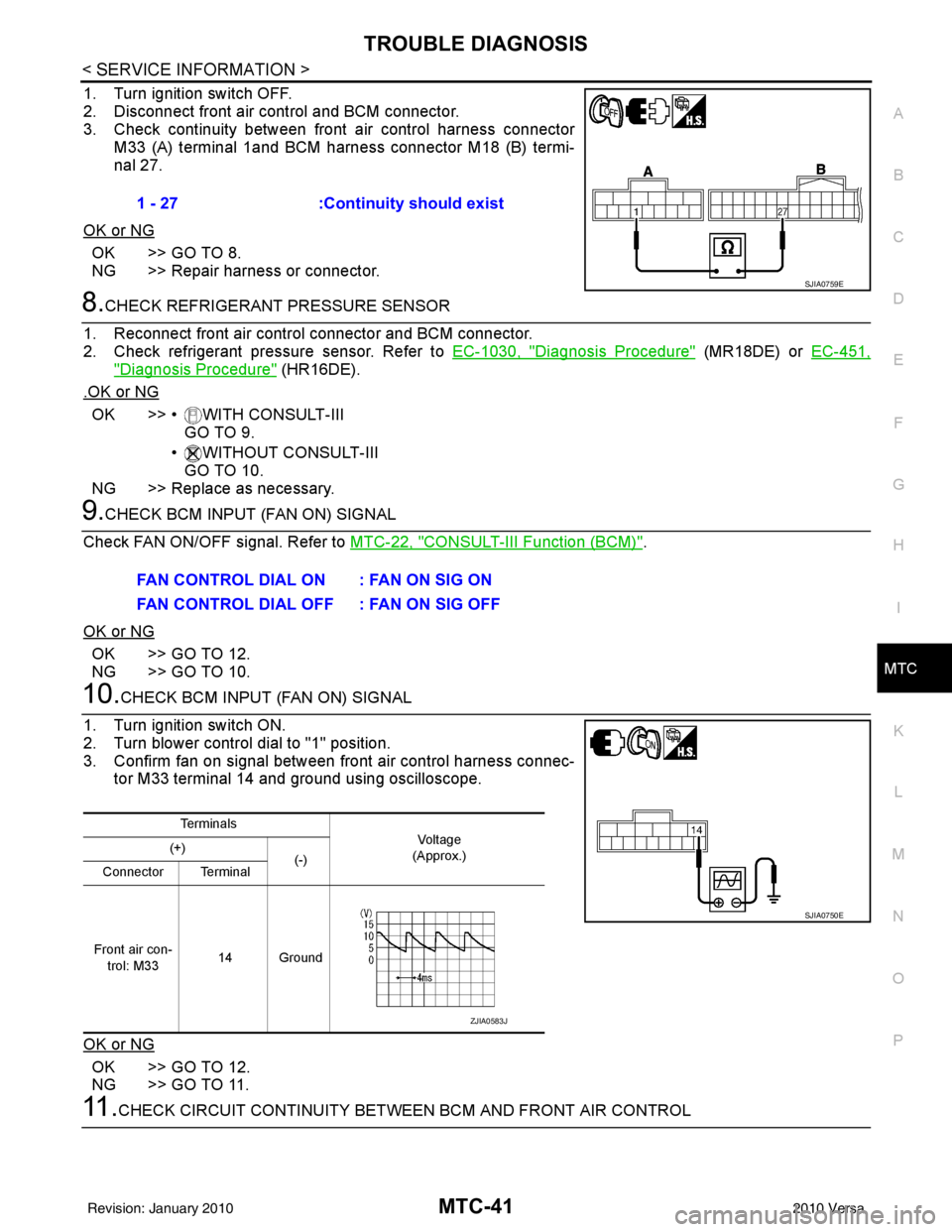
1. Turn ignition switch OFF.
2. Disconnect front air control and BCM connector.
3. Check continuity between front air control harness connector
M33 (A) terminal 1and BCM harness connector M18 (B) termi-
nal 27.
OK or NG
OK >> GO TO 8.
NG >> Repair harness or connector.
8.CHECK REFRIGERANT PRESSURE SENSOR
1. Reconnect front air control connector and BCM connector.
2. Check refrigerant pressure sensor. Refer to EC-1030, "
Diagnosis Procedure" (MR18DE) or EC-451,
"Diagnosis Procedure" (HR16DE).
.OK or NG
OK >> • WITH CONSULT-III GO TO 9.
• WITHOUT CONSULT-III GO TO 10.
NG >> Replace as necessary.
9.CHECK BCM INPUT (FAN ON) SIGNAL
Check FAN ON/OFF signal. Refer to MTC-22, "
CONSULT-III Function (BCM)".
OK or NG
OK >> GO TO 12.
NG >> GO TO 10.
10.CHECK BCM INPUT (FAN ON) SIGNAL
1. Turn ignition switch ON.
2. Turn blower control dial to "1" position.
3. Confirm fan on signal between front air control harness connec- tor M33 terminal 14 and ground using oscilloscope.
OK or NG
OK >> GO TO 12.
NG >> GO TO 11.
11 .CHECK CIRCUIT CONTINUITY BETWEE N BCM AND FRONT AIR CONTROL
1 - 27
:Continuity should exist
SJIA0759E
FAN CONTROL DIAL ON : FAN ON SIG ON
FAN CONTROL DIAL OFF : FAN ON SIG OFF
Te r m i n a l s
Vo l ta g e
(Approx.)
(+)
(-)
Connector Terminal
Front air con- trol: M33 14 Ground
SJIA0750E
ZJIA0583J
Revision: January 20102010 Versa
Page 3321 of 3745

MTC-42
< SERVICE INFORMATION >
TROUBLE DIAGNOSIS
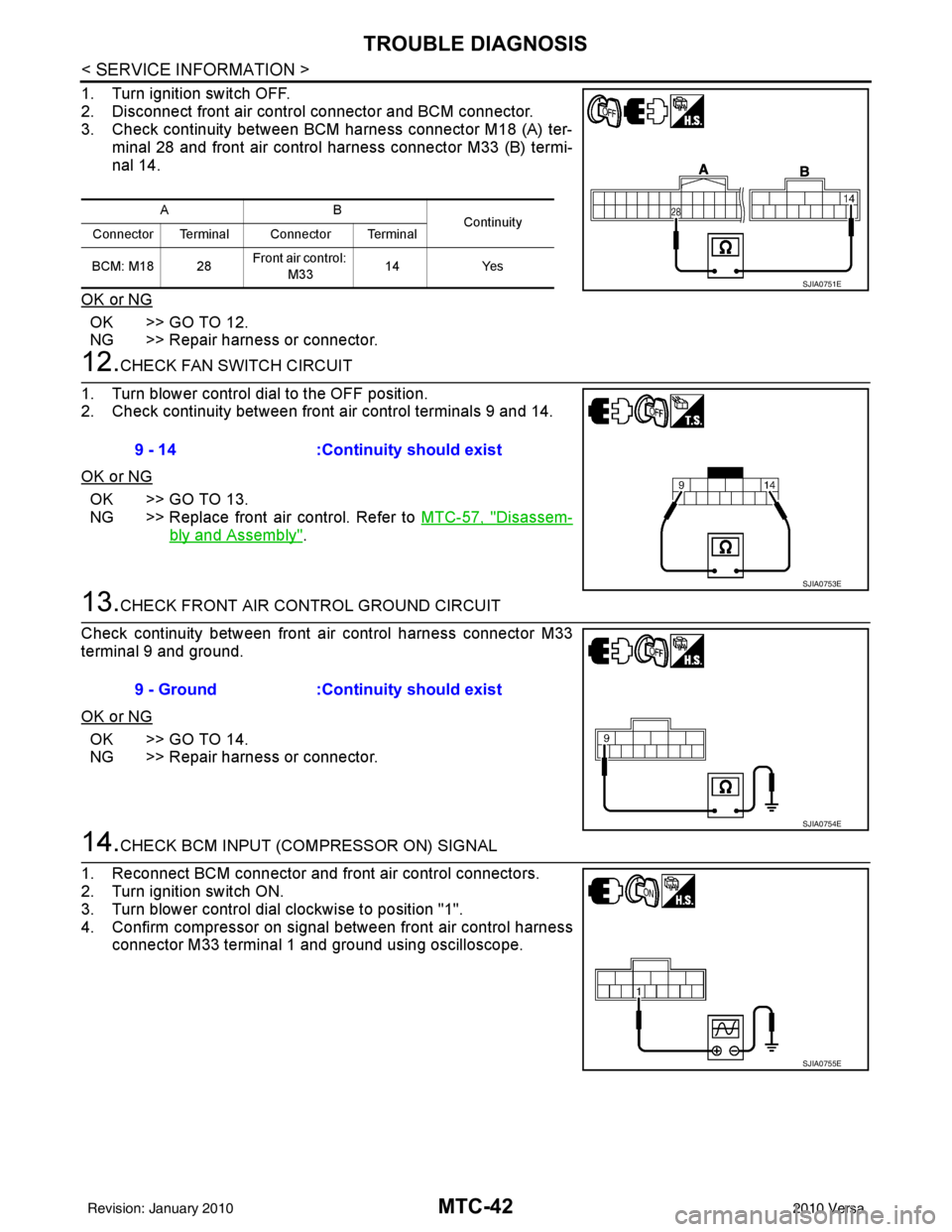
1. Turn ignition switch OFF.
2. Disconnect front air control connector and BCM connector.
3. Check continuity between BCM harness connector M18 (A) ter-minal 28 and front air control harness connector M33 (B) termi-
nal 14.
OK or NG
OK >> GO TO 12.
NG >> Repair harness or connector.
12.CHECK FAN SWITCH CIRCUIT
1. Turn blower control dial to the OFF position.
2. Check continuity between front air control terminals 9 and 14.
OK or NG
OK >> GO TO 13.
NG >> Replace front air control. Refer to MTC-57, "
Disassem-
bly and Assembly".
13.CHECK FRONT AIR CONTROL GROUND CIRCUIT
Check continuity between front air control harness connector M33
terminal 9 and ground.
OK or NG
OK >> GO TO 14.
NG >> Repair harness or connector.
14.CHECK BCM INPUT (COMPRESSOR ON) SIGNAL
1. Reconnect BCM connector and front air control connectors.
2. Turn ignition switch ON.
3. Turn blower control dial clockwise to position "1".
4. Confirm compressor on signal between front air control harness connector M33 terminal 1 and ground using oscilloscope.
AB Continuity
Connector Terminal Connector Terminal
BCM: M18 28 Front air control:
M33 14
Yes
SJIA0751E
9 - 14 :Continuity should exist
SJIA0753E
9 - Ground :Continuity should exist
SJIA0754E
SJIA0755E
Revision: January 20102010 Versa
Page 3322 of 3745

TROUBLE DIAGNOSISMTC-43
< SERVICE INFORMATION >
C
DE
F
G H
I
K L
M A
B
MTC
N
O P
OK or NG
OK >> GO TO 15.
NG >> GO TO 17.
15.CHECK A/C SWITCH CIRCUIT
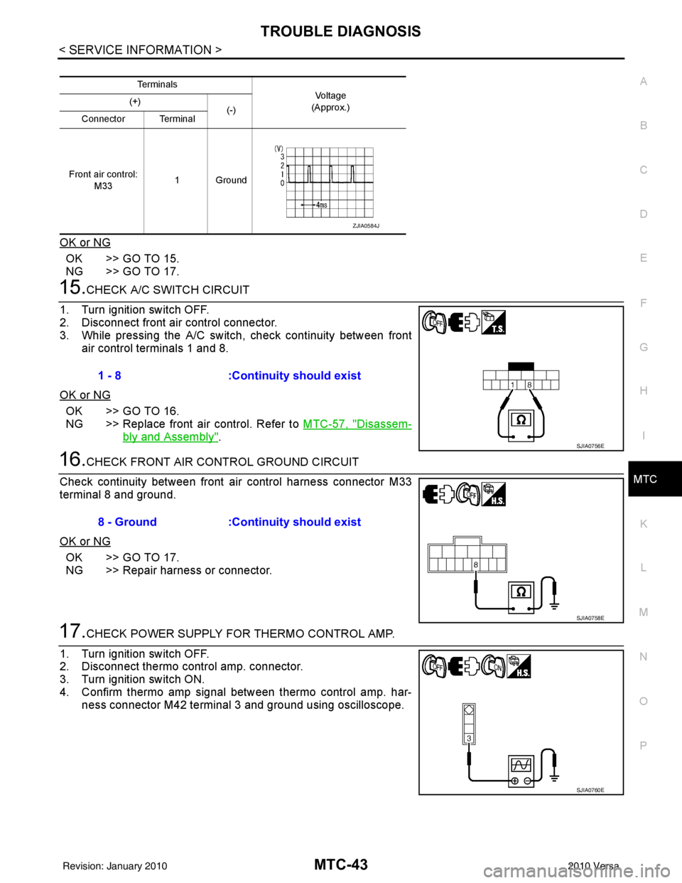
1. Turn ignition switch OFF.
2. Disconnect front air control connector.
3. While pressing the A/C switch, check continuity between front air control terminals 1 and 8.
OK or NG
OK >> GO TO 16.
NG >> Replace front air control. Refer to MTC-57, "
Disassem-
bly and Assembly".
16.CHECK FRONT AIR CONTROL GROUND CIRCUIT
Check continuity between front air control harness connector M33
terminal 8 and ground.
OK or NG
OK >> GO TO 17.
NG >> Repair harness or connector.
17.CHECK POWER SUPPLY FOR THERMO CONTROL AMP.
1. Turn ignition switch OFF.
2. Disconnect thermo control amp. connector.
3. Turn ignition switch ON.
4. Confirm thermo amp signal between thermo control amp. har- ness connector M42 terminal 3 and ground using oscilloscope.
Te r m i n a l s
Voltag e
(Approx.)
(+)
(-)
Connector Terminal
Front air control: M33 1Ground
ZJIA0584J
1 - 8
:Continuity should exist
SJIA0756E
8 - Ground :Continuity should exist
SJIA0758E
SJIA0760E
Revision: January 20102010 Versa
Page 3400 of 3745

IPDM E/R (INTELLIGENT POWER DISTRIBUTION MODULE ENGINE ROOM)
PG-17
< SERVICE INFORMATION >
C
D E
F
G H
I
J
L
M A
B
PG
N
O P
IPDM E/R (INTELLIGENT POWER DISTRIBUTION MODULE ENGINE
ROOM)
System DescriptionINFOID:0000000005395354
• IPDM E/R (Intelligent Power Distribution Module Engi ne Room) integrates the relay box and fuse block
which were originally placed in engine compartment. It controls integrated relays via IPDM E/R control cir-
cuits.
• IPDM E/R-integrated control circuits perform ON-OFF operation of relays, CAN communication control, oil pressure switch signal reception, etc.
• It controls operation of each electrical co mponent via ECM, BCM and CAN communication lines.
CAUTION:
None of the IPDM E/R integr ated relays can be removed.
SYSTEMS CONTROLLED BY IPDM E/R
1. Lamp control
Using CAN communication lines, it receives signals from the BCM and controls the following lamps:
• Headlamps (High, Low)
• Parking lamps
• Tail and license plate lamps
• Front fog lamps
2. Wiper control Using CAN communication lines, it receives signals from the BCM and controls the front wipers.
3. Rear window defogger relay control Using CAN communication lines, it receives signals from the BCM and controls the rear window defogger
relay.
4. A/C compressor control Using CAN communication lines, it receives signal s from the ECM and controls the A/C compressor
(magnet clutch).
5. Starter control Using CAN communication lines, it receives signals from the BCM and controls the starter relay.
6. Cooling fan control Using CAN communication lines, it receives signals from the ECM and controls the cooling fan relays.
7. Horn control Using CAN communication lines, it receives signals from the BCM and controls the horn relay.
8. Daytime light system control (Canada only) Using CAN communication lines, it receives signals from the BCM and controls the daytime light relay.
CAN COMMUNICATION LINE CONTROL
With CAN communication, by connecting each control unit using two communication lines (CAN L-line, CAN
H-line), it is possible to transmit a maximum amount of information with minimum wiring. Each control unit can
transmit and receive data, and reads necessary information only.
1. Fail-safe control • When CAN communication with other control units is impossible, IPDM E/R performs fail-safe control.
After CAN communication returns to normal operation, it also returns to normal control.
• Operation of control parts by IPDM E/ R during fail-safe mode is as follows:
Controlled system Fail-safe mode
Headlamp • With the ignition switch ON, headlamp low relay is ON, headlamp high relays are OFF, and
daytime light system (Canada only) is OFF.
• With the ignition switch OFF, the headlamp relays are OFF.
Tail, license plate and parking lamps • With the ignition switch ON, the tail lamp relay is ON. • With the ignition switch OFF, the tail lamp relay is OFF.
Cooling fan • With the ignition switch ON, cooling fan relay-1, relay-2, and relay-3 are ON.
• With the ignition switch OFF, all cooling fan relays are OFF.
Front wiper Until the ignition switch is turned off, the front wiper relays remain in the same status they
were in just before fail
−safe control was initiated.
Revision: January 20102010 Versa
Page 3401 of 3745

PG-18
< SERVICE INFORMATION >
IPDM E/R (INTELLIGENT POWER DISTRIBUTION MODULE ENGINE ROOM)
IPDM E/R STATUS CONTROL
In order to save power, IPDM E/R switches status by itself based on each operating condition.
1. CAN communication status • CAN communication is normally performed with other control units.
• Individual unit control by IPDM E/R is normally performed.
• When sleep request signal is received from BCM, mode is switched to sleep waiting status.
2. Sleep waiting status • Process to stop CAN communication is activated.
• All systems controlled by IPDM E/R are stopped. When 1 second has elapsed after CAN communica-tion with other control units is st opped, mode switches to sleep status.
3. Sleep status • IPDM E/R operates in low current-consumption mode.
• CAN communication is stopped.
• When a change in CAN communication signal is detec ted, mode switches to CAN communication sta-
tus.
• When a change in ignition switch signal is detected, mode switches to CAN communication status.
CAN Communication System DescriptionINFOID:0000000005395355
Refer to LAN-7, "System Diagram".
Function of Detecting I gnition Relay MalfunctionINFOID:0000000005395356
• When the integrated ignition relay is stuck in a "closed contact" position and cannot be turned OFF, IPDM E/
R turns ON tail and parking lamps for 10 minutes to indicate IPDM E/R malfunction.
• When the state of the integrated ignition relay does not agree with the state of the ignition switch signal
received via CAN communication, the IPDM E/R activates the tail lamp relay.
NOTE:
When the ignition switch is turned ON, the tail lamps are OFF.
CONSULT-III Function (IPDM E/R)INFOID:0000000005395357
CONSULT-III can display each diagnostic item us ing the diagnostic test modes shown following.
SELF-DIAGNOSTIC RESULTS
Display Item List
Rear window defoggerRear window defogger relay OFF
A/C compressor A/C relay is OFF
Front fog lamps Front fog lamp relay OFF
Controlled system
Fail-safe mode
Ignition switch signalIgnition relay status Tail lamp relay
ON ON —
OFF OFF —
ON OFF —
OFF ON ON (10 minutes)
IPDM E/R diagnostic Mode Description
SELF-DIAG RESULTS Displays IPDM E/R self-diagnosis results. DATA MONITOR Displays IPDM E/R input/output data in real time.
CAN DIAG SUPPORT MNTR The result of transmit/receive diagnosis of CAN communication can be read. ACTIVE TEST Operation of electrical loads can be checked by sending drive signal to them.
Revision: January 20102010 Versa
Page 3403 of 3745

PG-20
< SERVICE INFORMATION >
IPDM E/R (INTELLIGENT POWER DISTRIBUTION MODULE ENGINE ROOM)
*1 Perform monitoring of IPDM E/R data with the ignition switch ON. When the ignition switch is in ACC position, display may no t be cor-
rect.
*2 This item is displayed, but does not function.
CAN DIAG SUPPORT MNTR
Refer to LAN-9, "Description" .
ACTIVE TEST
Display Item List
Auto Active TestINFOID:0000000005395358
DESCRIPTION
• In auto active test mode, operation inspection can be performed when IPDM E/R sends a drive signal to the
following systems:
- Rear window defogger
- Front wipers
- Tail, license and parking lamps
- Daytime lamp system (Canada only)
- Front fog lamps
- Headlamps (High, Low)
- A/C compressor (magnet clutch)
- Cooling fan
OPERATION PROCEDURE
1. Close hood and front door RH, and lift wiper arms away from windshield (to prevent glass damage by wiper operation).
NOTE:
When auto active test is performed with hood opened, sprinkle water on windshield beforehand.
2. Turn ignition switch OFF.
3. Turn ignition switch ON and, within 20 seconds, pres s front door switch LH 20 times. Then turn ignition
switch OFF.
4. Turn ignition switch ON within 10 seconds after ignition switch OFF.
5. When auto active test mode is actuated, horn chirps once.
6. After a series of operations is repeated three times, auto active test is completed.
Theft warning
horn request THFT HRN REQ ON/OFF
XX Signal status input from BCM
Horn chirp HORN CHIRP ON/OFF XX Output status of IPDM E/R
Daytime light re-
quest DTRL REQ ON/OFF
XX Signal status input from BCM
Item name
CONSULT-III
screen display Display or unit Monitor item selection
Description
ALL
SIGNALS MAIN
SIGNALS SELECTION
FROM MENU
Test name CONSULT-III screen display Description
Head, tail, fog lamp output EXTERNAL LAMPS With a certain ON-OFF operation (OFF, TAIL, LO, HI, FOG), the front
fog lamp, headlamp low, headlamp high RH, headlamp high LH, and
tail lamp relays can be operated.
Rear defogger output REAR DEFOGGER With a certain ON-OFF operation, the rear defogger relay can be oper-
ated.
Front wiper (HI, LO) output FRONT WIPER With a certain operation (OFF, HI ON, LO ON), the front wiper relays
(Lo, Hi) can be operated.
Cooling fan output MOTOR FAN With a certain operation (1, 2, 3, 4), the cooling fan relays can be oper-
ated.
Horn output HORN With a certain ON-OFF operation, the horn relay can be operated.
Revision: January 20102010 Versa
Page 3410 of 3745

IPDM E/R (INTELLIGENT POWER DISTRIBUTION MODULE ENGINE ROOM)
PG-27
< SERVICE INFORMATION >
C
D E
F
G H
I
J
L
M A
B
PG
N
O PIPDM E/R Power/Ground Circuit InspectionINFOID:0000000005395362
1.FUSE AND FUSIBLE LINK INSPECTION
Check that the following fusible links or IPDM E/R fuses are not blown.
OK or NG
OK >> GO TO 2.
NG >> Replace fuse or fusible link.
2.POWER CIRCUIT INSPECTION
1. Turn ignition switch OFF.
2. Disconnect IPDM E/R harness connector E42.
3. Check voltage between IPDM E/R harness connector E42 terminals 1, 2 and ground.
50 V Front fog lamp (LH) Output ON or
STARTLighting
switch must
be in the 2ND
position
(LOW beam
is ON) and
the front fog
lamp switch OFF
0V
ON Battery voltage
51 W Front fog lamp (RH) Output ON or
START Lighting
switch must
be in the 2ND
position
(LOW beam
is ON) and
the front fog
lamp switch OFF
0V
ON Battery voltage
52 L LH Low beam head-
lamp Output — Lighting switch in 2nd position Battery voltage
54 P RH Low beam head-
lamp
Output — Lighting switch in 2nd position Battery voltage
55 G LH High beam head-
lamp
Output —Lighting switch in 2nd position
and placed in HIGH or PASS
position
Battery voltage
56 Y RH High beam head-
lamp Output —Lighting switch in 2nd position
and placed in HIGH or PASS
position Battery voltage
59 B Ground Input ——0V
60 R Rear window defogger
relay
OutputON or
START Rear defogger Switch ON
Battery voltage
Rear defogger Switch OFF 0V
Te r m i n a l
Wire
color Signal name Signal
input/
output Measuring condition
Reference value
(Approx.)
Ignition
switch Operation or condition
Terminal No.
Signal nameFuse, fusible link No.
1, 2 Battery power a, b, d
Revision: January 20102010 Versa
Page 3425 of 3745

PG-42
< SERVICE INFORMATION >
HARNESS
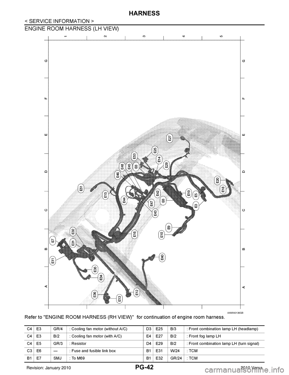
ENGINE ROOM HARNESS (LH VIEW)
Refer to "ENGINE ROOM HARNESS (RH VIEW)" for continuation of engine room harness.
AAMIA0136GB
C4 E3 GR/4 : Cooling fan motor (without A/C) D3 E25 B/3 : Front combination lamp LH (headlamp)
C4 E3 B/2 : Cooling fan motor (with A/C) E4 E27 B/2 : Front fog lamp LH
C4 E5 GR/3 : Resistor D4 E29 B/2 : Front combination lamp LH (turn signal)
C3 E6 — : Fuse and fusible link box B1 E31 W/24 : TCM
B1 E7 SMJ : To M69 B1 E32 GR/24 : TCM
Revision: January 20102010 Versa