Page 42 of 3745

A/T CONTROL SYSTEMAT-25
< SERVICE INFORMATION >
DE
F
G H
I
J
K L
M A
B
AT
N
O P
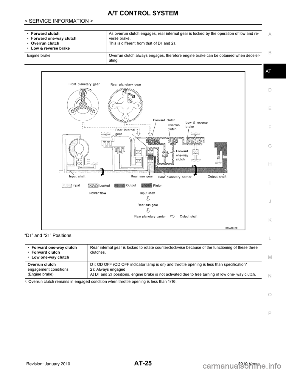
“D
1” and “21” Positions
*: Overrun clutch remains in engaged condition when throttle opening is less than 1/16. •
Forward clutch
• Forward one-way clutch
• Overrun clutch
• Low & reverse brake As overrun clutch engages, rear internal gear is locked by the operation of low and re-
verse brake.
This is different from that of D
1 and 21.
Engine brake Overrun clutch always engages, therefore engine brake can be obtained when deceler-
ating.
SCIA1816E
• Forward one-way clutch
• Forward clutch
• Low one-way clutch Rear internal gear is locked to rotate counterclockwise because of the functioning of these three
clutches.
Overrun clutch
engagement conditions
(Engine brake) D
1: OD OFF (OD OFF indicator lamp is on) and th
rottle opening is less than specification*
2
1: Always engaged
At D
1 and 21 positions, engine brake is not activated due to free turning of low one- way clutch.
Revision: January 20102010 Versa
Page 251 of 3745

AT-234
< SERVICE INFORMATION >
TRANSAXLE ASSEMBLY
2. Disconnect the following connectors and remove the wire har-ness.
• Input speed sensor harness connector (1)
• Terminal cord assembly harness connector (2)
• Transmission range switch connector (3)
• output speed sensor harness connector (4)
3. Remove the four drive plate to torque converter bolts. NOTE:
Rotate the crankshaft clockwise as viewed from front of engine
for access to drive plate to torque converter bolts.
4. Put matching marks on the drive plate and torque converter. CAUTION:
For matching marks, use paint. Never dama ge the drive plate or torque converter.
5. Remove the transaxle to engine and engine to transaxle bolts.
6. Separate the transaxle from the engine. CAUTION:
Secure torque converter to prevent it from dropping.
7. If necessary, remove the following from the transaxle: • output speed sensor
• Input speed sensor
• Fluid cooler tubes (1) and copper washers
• A/T fluid level gauge (2) and charging pipe (3)
• Transmission range switch
• Air breather hose
• Engine mounting bracket (LH)
• Any necessary brackets
INSTALLATION
Installation is in the reverse order of removal.
CAUTION:
WCIA0647E
WCIA0616E
WCIA0648E
Revision: January 20102010 Versa
Page 252 of 3745

TRANSAXLE ASSEMBLYAT-235
< SERVICE INFORMATION >
DE
F
G H
I
J
K L
M A
B
AT
N
O P
• When replacing an engine or transmission you must make sure any dowels are installed correctly during re-assembly.
• Improper alignment caused by missing dowels may cause vibration, oil leaks or breakage of drive
train components.
• Do not reuse O-rings and copper washers. Refer to "COMPONENTS".
• When turning crankshaft, turn it clockwise as viewed from the front of the engine.
• When tightening the bolts for th e torque converter while securing the crankshaft pulley bolt, be sure
to confirm the tightening torque of the crankshaft pulley bolt. Refer to EM-156
.
• After converter is installed to drive plate, ro tate crankshaft several turns to check that transaxle
rotates freely without binding.
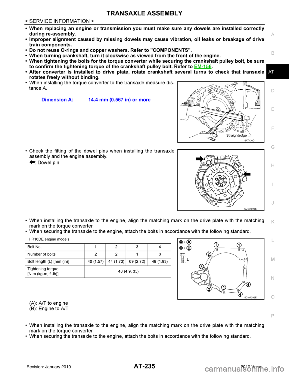
• When installing the torque converter to the transaxle measure dis- tance A.
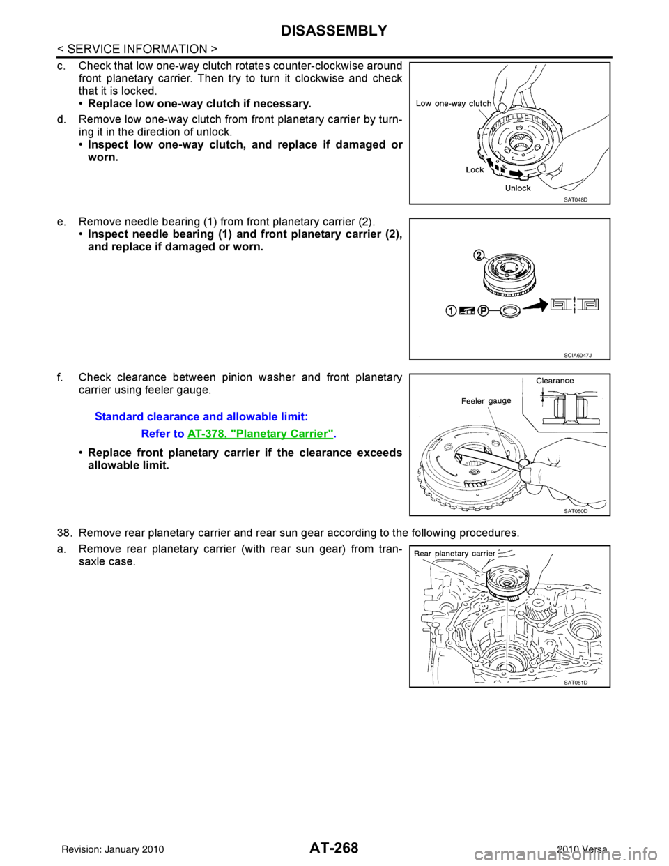
• Check the fitting of the dowel pins when installing the transaxle assembly and the engine assembly.
: Dowel pin
• When installing the transaxle to the engine, align the matching mark on the drive plate with the matching mark on the torque converter.
• When securing the transaxle to the engine, attach the bolts in accordance with the following standard.
HR16DE engine models
(A): A/T to engine
(B): Engine to A/T
• When installing the transaxle to the engine, align the matching mark on the drive plate with the matching mark on the torque converter.
• When securing the transaxle to the engine, attach the bolts in accordance with the following standard. Dimension A: 14.4 mm (0.567 in) or more
SAT430D
SCIA7698E
Bolt No.
1 2 34
Number of bolts 2 2 13
Bolt length (L) [mm (in)] 40 (1.5 7) 44 (1.73) 69 (2.72) 49 (1.93)
Tightening torque
[N·m (kg-m, ft-lb)] 48 (4.9, 35)
SCIA7096E
Revision: January 20102010 Versa
Page 274 of 3745
DISASSEMBLYAT-257
< SERVICE INFORMATION >
DE
F
G H
I
J
K L
M A
B
AT
N
O P
DISASSEMBLY
DisassemblyINFOID:0000000005397435
1. Drain ATF through drain hole.
2. Remove drain plug gasket from drain plug.
3. Remove torque converter.
4. Check torque converter one-way clutch using check tool as shown.
a. Insert check tool into groove of bearing support built into one- way clutch outer race.
b. When fixing bearing support with check tool, rotate one-way clutch spline using screwdriver.
c. Check that inner race rotates clockwise only. If not, replace torque converter assembly.
SCIA0003E
SAT008D
SAT009D
Revision: January 20102010 Versa
Page 285 of 3745

AT-268
< SERVICE INFORMATION >
DISASSEMBLY
c. Check that low one-way clutch rotates counter-clockwise aroundfront planetary carrier. Then try to turn it clockwise and check
that it is locked.
•Replace low one-way clutch if necessary.
d. Remove low one-way clutch from front planetary carrier by turn- ing it in the direction of unlock.
•Inspect low one-way clutch, and replace if damaged or
worn.
e. Remove needle bearing (1) from front planetary carrier (2). •Inspect needle bearing (1) and front planetary carrier (2),
and replace if damaged or worn.
f. Check clearance between pinion washer and front planetary carrier using feeler gauge.
•Replace front planetary carrier if the clearance exceeds
allowable limit.
38. Remove rear planetary carrier and rear sun gear according to the following procedures.
a. Remove rear planetary carrier (with rear sun gear) from tran- saxle case.
SAT048D
SCIA6047J
Standard clearance and allowable limit:
Refer to AT-378, "
Planetary Carrier".
SAT050D
SAT051D
Revision: January 20102010 Versa
Page 373 of 3745
AT-356
< SERVICE INFORMATION >
ASSEMBLY
3. Install forward clutch assembly and overrun clutch assembly (1)into transaxle case.
CAUTION:
• Align teeth of low & reverse brake drive plates beforeinstalling.
• Make sure that bearing retainer seal rings are not spread.
4. Install needle bearing (1) on bearing retainer. CAUTION:
Be careful with the dir ection of needle bearing.
5. Install thrust washer (1) on overrun clutch hub (2). CAUTION:
Align pawls of thrust washer (1) with holes of overrun
clutch hub (2).
6. Install overrun clutch hub (1) into forward clutch drum. CAUTION:
Align teeth of overrun clutch drive plates before installing.
7. Hold forward clutch hub, and check that rear internal gear locks when tried to rotate counterclockwise.
CAUTION:
If rear internal gear rotat es counterclockwise, check instal-
lation direction of forward one-way clutch.
SCIA5900J
SCIA8014E
SCIA5899J
SCIA5898J
SCIA7078E
Revision: January 20102010 Versa
Page 375 of 3745
AT-358
< SERVICE INFORMATION >
ASSEMBLY
13. Install needle bearing (1) on front planetary carrier (2).CAUTION:
Be careful with the direct ion of needle bearing (1).
14. Install low one-way clutch to front planetary carrier by turning it in the direction of unlock.
15. Check that low one-way clutch rotates counterclockwise around front planetary carrier. Then try to turn it clockwise and check
that it is locked.
16. Install front planetary carrier (2) and low one-way clutch (1) as a set into transaxle case.
17. Install snap ring into transaxle case using a flat-bladed screw- driver.
18. Install needle bearing (1) on front sun gear (2). CAUTION:
Be careful with the direct ion of needle bearing (1).
SCIA6047J
SAT048D
SCIA5896J
SCIA3633E
SCIA6960E
Revision: January 20102010 Versa
Page 459 of 3745
![NISSAN LATIO 2010 Service Repair Manual AV-62
< SERVICE INFORMATION >[AUDIO WITH NAVIGATION]
AUDIO
On-Board Diagnosis
INFOID:0000000005988546
METHOD OF STARTING
1. Start the engine.
2. Turn OFF audio.
3. While pressing the “SET UP” s wi NISSAN LATIO 2010 Service Repair Manual AV-62
< SERVICE INFORMATION >[AUDIO WITH NAVIGATION]
AUDIO
On-Board Diagnosis
INFOID:0000000005988546
METHOD OF STARTING
1. Start the engine.
2. Turn OFF audio.
3. While pressing the “SET UP” s wi](/manual-img/5/57358/w960_57358-458.png)
AV-62
< SERVICE INFORMATION >[AUDIO WITH NAVIGATION]
AUDIO
On-Board Diagnosis
INFOID:0000000005988546
METHOD OF STARTING
1. Start the engine.
2. Turn OFF audio.
3. While pressing the “SET UP” s witch, turn the MENU dial coun-
terclockwise 3 clicks or more first, then clockwise and counter-
clockwise 3 clicks or more, respectively. (After the diagnosis
mode starts, the initial screen of the diagnosis mode appears.)
• On-board diagnosis can be performed in the service test mode.
• On-board diagnosis checks that the system can be operated normally.
Service test mode
46 (L) — AUX sound
signal LH—— —
——
47 (W) — USB D- — — —— —
48 (GR) — AUX sound
signal RH—— —
——
49 (G) — USB D+ — — —— —
50 (BR) — AUX sound
signal
ground—— —
——
51 (R) — USB V BUS
signal—— —
——
53 (GR) — SHIELD — — —— —
54 — Satellite an-
tenna signal
—— —
——
55 — GPS anten-
na signal—— —
——
56 — SHIELD — — —— —
57 — Antenna on
signal—— —
——
58 — Main anten-
na signal
—— —
——
Te r m i n a l
(Wire color) ItemSignal
input/
output Condition
Reference value
(Approx.) Example of symp-
tom
+– Ignition
switch Operation
JSNIA2456ZZ
Mode
ItemContent
Service version —The version data of the parts is shown
displayed.
Revision: January 20102010 Versa