2010 NISSAN LATIO Lan system
[x] Cancel search: Lan systemPage 1091 of 3745
![NISSAN LATIO 2010 Service Repair Manual CVT-58
< SERVICE INFORMATION >[RE0F08B]
U1000 CAN COMM CIRCUIT
Diagnosis Procedure
INFOID:0000000005397804
1.CHECK CAN COMMUNICATION CIRCUIT
With CONSULT-III1. Turn ignition switch ON and start engine NISSAN LATIO 2010 Service Repair Manual CVT-58
< SERVICE INFORMATION >[RE0F08B]
U1000 CAN COMM CIRCUIT
Diagnosis Procedure
INFOID:0000000005397804
1.CHECK CAN COMMUNICATION CIRCUIT
With CONSULT-III1. Turn ignition switch ON and start engine](/manual-img/5/57358/w960_57358-1090.png)
CVT-58
< SERVICE INFORMATION >[RE0F08B]
U1000 CAN COMM CIRCUIT
Diagnosis Procedure
INFOID:0000000005397804
1.CHECK CAN COMMUNICATION CIRCUIT
With CONSULT-III1. Turn ignition switch ON and start engine.
2. Select “SELF-DIAG RESULTS” mode fo r “TRANSMISSION” with CONSULT-III.
Is any malfunction of the
“U1000” indicated?
YES >> Print out CONSULT-III screen, go to LAN section. Refer to LAN-26, "CAN System Specification
Chart" .
NO >> INSPECTION END
Revision: January 20102010 Versa
Page 1215 of 3745

COMBINATION METERSDI-5
< SERVICE INFORMATION >
C
DE
F
G H
I
J
L
M A
B
DI
N
O P
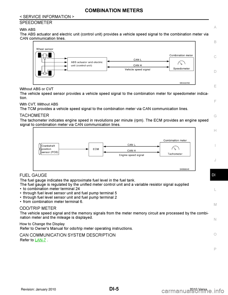
SPEEDOMETER
With ABS
The ABS actuator and electric unit (control unit) provi des a vehicle speed signal to the combination meter via
CAN communication lines.
Without ABS or CVT
The vehicle speed sensor provides a vehicle speed signal to the combination meter for speedometer indica-
tion.
With CVT, Without ABS
The TCM provides a vehicle speed signal to the combination meter via CAN communication lines.
TACHOMETER
The tachometer indicates engine speed in revolutions per minute (rpm). The ECM provides an engine speed
signal to combination meter via CAN communication lines.
FUEL GAUGE
The fuel gauge indicates the approximate fuel level in the fuel tank.
The fuel gauge is regulated by the unified meter control unit and a variable resistor signal supplied
• to combination meter terminal 24
• through fuel level sensor unit and fuel pump terminal 5
• through fuel level sensor unit and fuel pump terminal 2
• from combination meter terminal 6.
ODO/TRIP METER
The vehicle speed signal and the memory signals from the meter memory circuit are processed by the combi-
nation meter and the mileage is displayed.
How to Change the Display
Refer to Owner's Manual for odo/trip meter operating instructions.
CAN COMMUNICATION SYSTEM DESCRIPTION
Refer to LAN-7 .
WKIA5370E
SKIB6904E
Revision: January 20102010 Versa
Page 1221 of 3745

COMBINATION METERSDI-11
< SERVICE INFORMATION >
C
DE
F
G H
I
J
L
M A
B
DI
N
O P
Self-Diagnosis Mode of Combination MeterINFOID:0000000005395014
SELF-DIAGNOSIS MODE FUNCTION
• Self-diagnosis can check for continuity between meter control circuit and each meter (speedometer, tachom- eter and fuel gauge).
• Self-diagnosis can check for odo/trip meter and A/T indi cator (with A/T) or CVT indicator (with CVT) seg-
ment, low-fuel level warning lamp, low water temperature indicator lamp, and high water temperature warn-
ing lamp.
OPERATION PROCEDURE
1. Turn the ignition switch ON, and switch the odo/trip meter to “trip A” or “trip B”. NOTE:
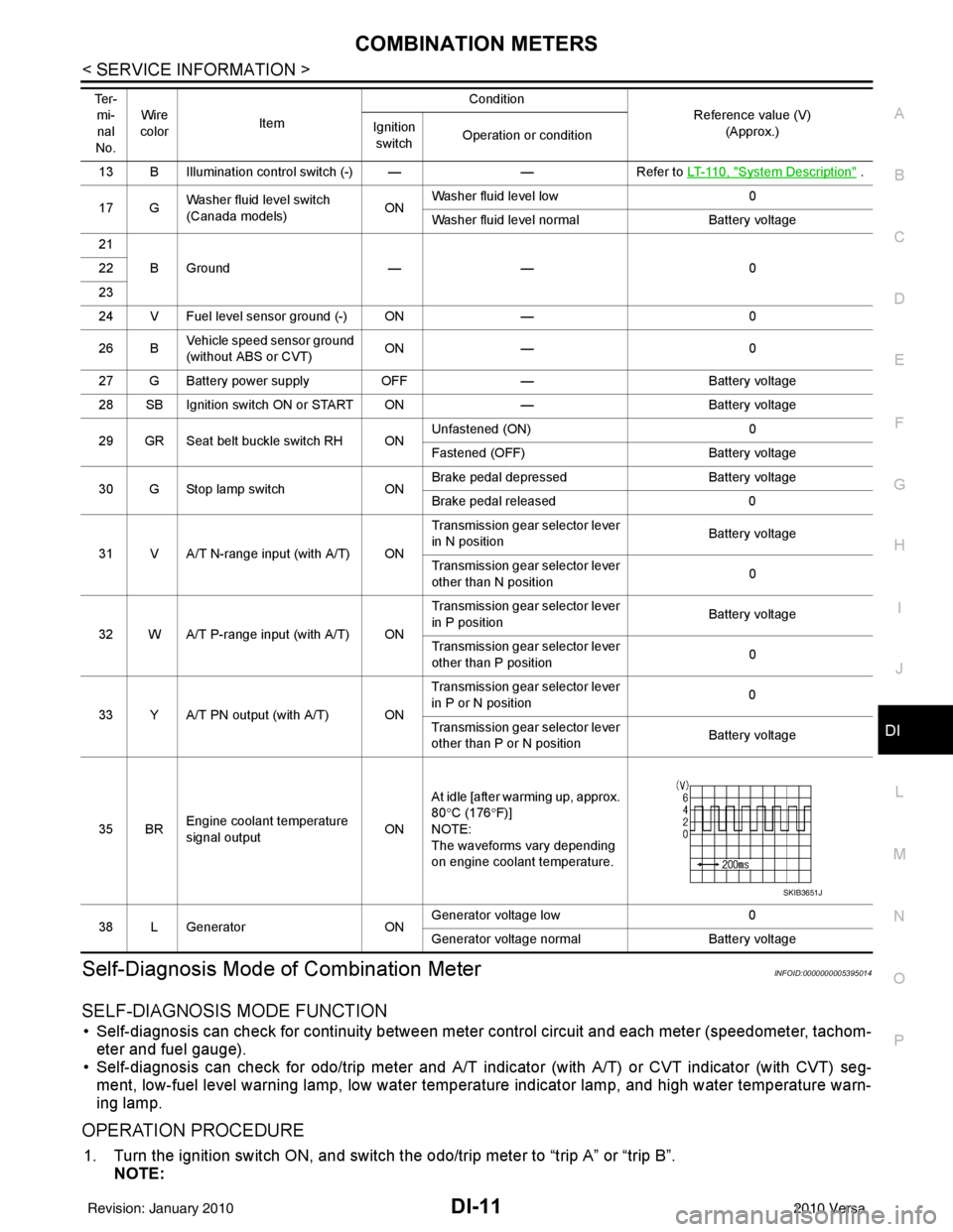
13 B Illumination control switch (-) — —Refer to LT-110, "System Description" .
17 G Washer fluid level switch
(Canada models)
ONWasher fluid level low
0
Washer fluid level normal Battery voltage
21 BGround —— 0
22
23
24 V Fuel level sensor ground (-) ON —0
26 B Vehicle speed sensor ground
(without ABS or CVT) ON
— 0
27 G Battery power supply OFF— Battery voltage
28 SB Ignition switch ON or START ON —Battery voltage
29 GR Seat belt buckle switch RH ON Unfastened (ON)
0
Fastened (OFF) Battery voltage
30 G Stop lamp switch ONBrake pedal depressed
Battery voltage
Brake pedal released 0
31 V A/T N-range input (with A/T) ON Transmission gear selector lever
in N position
Battery voltage
Transmission gear selector lever
other than N position 0
32 W A/T P-range input (with A/T) ON Transmission gear selector lever
in P position
Battery voltage
Transmission gear selector lever
other than P position 0
33 Y A/T PN output (with A/T) ON Transmission gear selector lever
in P or N position
0
Transmission gear selector lever
other than P or N position Battery voltage
35 BR Engine coolant temperature
signal output
ONAt idle [after warming up, approx.
80
°C (176 °F)]
NOTE:
The waveforms vary depending
on engine coolant temperature.
38 L Generator ONGenerator voltage low
0
Generator voltage no rmal Battery voltage
Te r -
mi-
nal
No. Wire
color Item Condition
Reference value (V)
(Approx.)
Ignition
switch Operation or condition
SKIB3651J
Revision: January 20102010 Versa
Page 1223 of 3745

COMBINATION METERSDI-13
< SERVICE INFORMATION >
C
DE
F
G H
I
J
L
M A
B
DI
N
O P
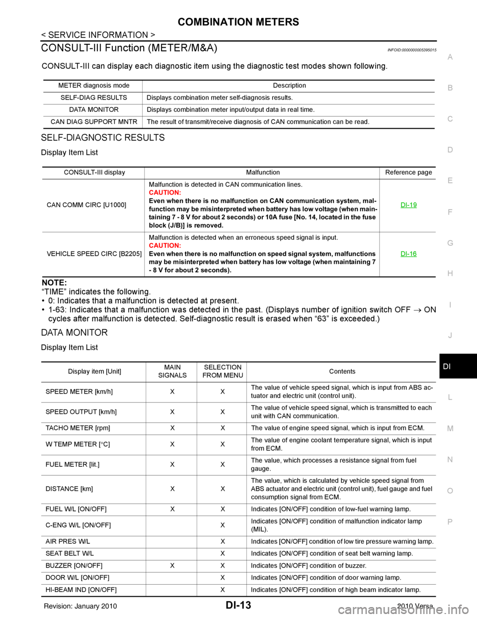
CONSULT-III Function (METER/M&A)INFOID:0000000005395015
CONSULT-III can display each diagnostic item us ing the diagnostic test modes shown following.
SELF-DIAGNOSTIC RESULTS
Display Item List
NOTE:
“TIME” indicates the following.
• 0: Indicates that a malfunction is detected at present.
• 1-63: Indicates that a malfunction was detected in the past. (Displays number of ignition switch OFF → ON
cycles after malfunction is detected. Self-di agnostic result is erased when “63” is exceeded.)
DATA MONITOR
Display Item List
METER diagnosis mode Description
SELF-DIAG RESULTS Displays combination meter self-diagnosis results. DATA MONITOR Displays combination meter input/output data in real time.
CAN DIAG SUPPORT MNTR The result of transmit/receive diagnosis of CAN communication can be read.
CONSULT-III display MalfunctionReference page
CAN COMM CIRC [U1000] Malfunction is detected in CAN communication lines.
CAUTION:
Even when there is no malfuncti
on on CAN communication system, mal-
function may be misinterpreted when battery has low voltage (when main-
taining 7 - 8 V for about 2 seconds) or 10A fuse [No. 14, located in the fuse
block (J/B)] is removed. DI-19
VEHICLE SPEED CIRC [B2205]
Malfunction is detected when an erroneous speed signal is input.
CAUTION:
Even when there is no malfunction
on speed signal system, malfunctions
may be misinterpreted when battery has low voltage (when maintaining 7
- 8 V for about 2 seconds). DI-16
Display item [Unit]
MAIN
SIGNALS SELECTION
FROM MENU Contents
SPEED METER [km/h] XXThe value of vehicle speed signa
l, which is input from ABS ac-
tuator and electric unit (control unit).
SPEED OUTPUT [km/h] XXThe value of vehicle speed signal, which is transmitted to each
unit with CAN communication.
TACHO METER [rpm] XX The value of engine speed signal, which is input from ECM.
W TEMP METER [ °C] X XThe value of engine coolant temperature signal, which is input
from ECM.
FUEL METER [lit.] XXThe value, which processes a resistance signal from fuel
gauge.
DISTANCE [km] XXThe value, which is calculated by vehicle speed signal from
ABS actuator and electric unit (control unit), fuel gauge and fuel
consumption signal from ECM.
FUEL W/L [ON/OFF] XX Indicates [ON/OFF] condition of low-fuel warning lamp.
C-ENG W/L [ON/OFF] XIndicates [ON/OFF] condition of malfunction indicator lamp
(MIL).
AIR PRES W/L X Indicates [ON/OFF] condition of low tire pressure warning lamp.
SEAT BELT W/L X Indicates [ON/OFF] condition of seat belt warning lamp.
BUZZER [ON/OFF] XX Indicates [ON/OFF] condition of buzzer.
DOOR W/L [ON/OFF] X Indicates [ON/OFF] condition of door warning lamp.
HI-BEAM IND [ON/OFF] X Indicates [ON/OFF] condition of high beam indicator lamp.
Revision: January 20102010 Versa
Page 1229 of 3745

COMBINATION METERSDI-19
< SERVICE INFORMATION >
C
DE
F
G H
I
J
L
M A
B
DI
N
O P
5.CHECK FUEL LEVEL SENSOR UNIT
Check fuel level sensor unit. Refer to DI-20, "
Electrical Component Inspection" .
OK or NG
OK >> Check fuel level sensor unit installation, and c heck whether the float arm interferes or binds with
any of the internal components in the fuel tank. Repair or replace malfunctioning part, if neces-
sary.
NG >> Replace fuel level sensor unit.
Fuel Gauge Fluctuates, Indica tes Wrong Value, or VariesINFOID:0000000005395022
1.CHECK FUEL GAUGE FLUCTUATION
Test drive vehicle to see if gauge fluctuates onl y during driving or at the instant of stopping.
Does the indication value vary only during dr iving or at the at the instant of stopping?
YES >> The pointer fluctuation may be caused by fuel level change in the fuel tank. Condition is normal.
NO >> Ask the customer about the situation when the symptom occurs in detail, and perform the trouble diagnosis.
Fuel Gauge Does Not Move to Full-positionINFOID:0000000005395023
1.OBSERVE FUEL GAUGE
Does it take a long time for the pointer to move to FULL position?
YES or NO
YES >> GO TO 2.
NO >> GO TO 3.
2.IDENTIFY FUELING CONDITION
Was the vehicle fueled with the ignition switch ON?
YES or NO
YES >> Be sure to fuel the vehicle with the ignition swit ch OFF. Otherwise, it will take a long time to move
to FULL position because of the c haracteristic of the fuel gauge.
NO >> GO TO 3.
3.OBSERVE VEHICLE POSITION
Is the vehicle parked on an incline?
YES or NO
YES >> Check the fuel level indicati on with vehicle on a level surface.
NO >> GO TO 4.
4.OBSERVE FUEL GAUGE POINTER
During driving, does the fuel gauge pointer move gradually toward EMPTY position?
YES or NO
YES >> Check the components. Refer to DI-20, "Electrical Component Inspection" .
NO >> The float arm may interfere or bind with any of the components in the fuel tank.
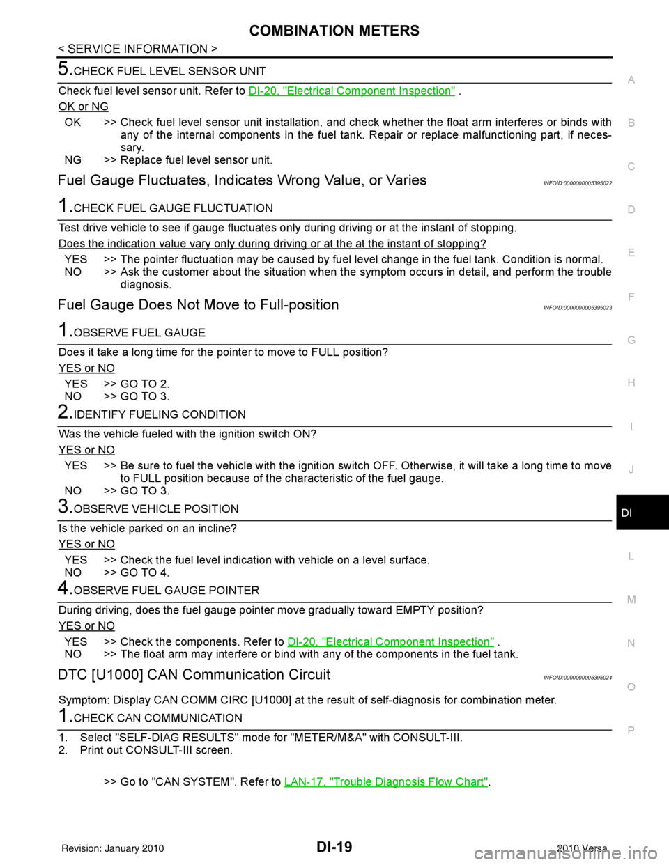
DTC [U1000] CAN Communication CircuitINFOID:0000000005395024
Symptom: Display CAN COMM CIRC [U1000] at the re sult of self-diagnosis for combination meter.
1.CHECK CAN COMMUNICATION
1. Select "SELF-DIAG RESULTS" mode for "METER/M&A" with CONSULT-III.
2. Print out CONSULT-III screen.
>> Go to "CAN SYSTEM". Refer to LAN-17, "
Trouble Diagnosis Flow Chart".
Revision: January 20102010 Versa
Page 1258 of 3745
![NISSAN LATIO 2010 Service Repair Manual DI-48
< SERVICE INFORMATION >
WARNING CHIME
DATA MONITOR
Display Item List
ACTIVE TEST
Display Item List
SELF-DIAG RESULTS
Display Item List
NOTE:
If “CAN communication [U1000]” is indicated, afte NISSAN LATIO 2010 Service Repair Manual DI-48
< SERVICE INFORMATION >
WARNING CHIME
DATA MONITOR
Display Item List
ACTIVE TEST
Display Item List
SELF-DIAG RESULTS
Display Item List
NOTE:
If “CAN communication [U1000]” is indicated, afte](/manual-img/5/57358/w960_57358-1257.png)
DI-48
< SERVICE INFORMATION >
WARNING CHIME
DATA MONITOR
Display Item List
ACTIVE TEST
Display Item List
SELF-DIAG RESULTS
Display Item List
NOTE:
If “CAN communication [U1000]” is indicated, after printing the monitor item, go to “LAN system”. Refer to
LAN-17, "
Trouble Diagnosis Flow Chart".
Trouble DiagnosisINFOID:0000000005395044
HOW TO PERFORM TROUBLE DIAGNOSIS
1. Confirm the symptom and customer complaint.
2. Understand the outline of system. Refer to DI-43, "
System Description".
3. Perform the preliminary inspection. Refer to "PRELIMINARY INSPECTION".
4. According to symptom chart, repair or replac e the cause of the malfunction. Refer to "SYMPTOM
CHART".
5. Does warning chime system operate normally? If it operates normally, GO TO 6. If not, GO TO 4.
6. Inspection End.
PRELIMINARY INSPECTION
BCM diagnostic test item Diagnostic mode
Description
Inspection by part WORK SUPPORT
Supports inspections and adjustments. Commands are transmitted to the BCM for
setting the status suitable for required operation, input/output signals are received
from the BCM and received data is displayed.
DATA MONITOR Displays BCM input/output data in real time. ACTIVE TEST Operation of electrical loads can be checked by sending drive signal to them.
SELF-DIAG RESULTS Displays BCM self-diagnosis results.
CAN DIAG SUPPORT MNTR The result of transmit/receive diagnosis of CAN communication can be read. ECU PART NUMBER BCM part number can be read.CONFIGURATION Performs BCM configuration read/write functions.
Monitored item ALL SIGNALS SELECTION
FROM MENU Contents
IGN ON SW XX Indicates [ON/OFF] condition of ignition switch.
KEY ON SW XX Indicates [ON/OFF] condition of key switch.
DOOR SW-DR XX Indicates [ON/OFF] condition of front door switch LH.
LIGHT SW 1ST XX Indicates [ON/OFF] condition of lighting switch.
BUCKLE SW XX Indicates [ON/OFF] condition of seat belt buckle switch LH.
Test item Malfunction is detected when···
IGN KEY WARN ALM This test is able to check key warning chime operation.
LIGHT WARN ALM This test is able to check light warning chime operation.
SEAT BELT WARN TEST This test is able to check seat belt warning chime operation.
Display item [Code] Malfunction is detected when...
CAN communication [U1000] Malfunction is detected in CAN communication.
Revision: January 20102010 Versa
Page 1291 of 3745
![NISSAN LATIO 2010 Service Repair Manual EC-26
< BASIC INSPECTION >[HR16DE]
INSPECTION AND ADJUSTMENT
• Each time electric throttle control actuator or ECM is replaced.
• Idle speed or ignition timing is out of specification.
IDLE AIR VO NISSAN LATIO 2010 Service Repair Manual EC-26
< BASIC INSPECTION >[HR16DE]
INSPECTION AND ADJUSTMENT
• Each time electric throttle control actuator or ECM is replaced.
• Idle speed or ignition timing is out of specification.
IDLE AIR VO](/manual-img/5/57358/w960_57358-1290.png)
EC-26
< BASIC INSPECTION >[HR16DE]
INSPECTION AND ADJUSTMENT
• Each time electric throttle control actuator or ECM is replaced.
• Idle speed or ignition timing is out of specification.
IDLE AIR VOLUME LEARNING
: Special Repair RequirementINFOID:0000000005398245
1.PRECONDITIONING
Make sure that all of the following conditions are satisfied.
Learning will be cancelled if any of the follo wing conditions are missed for even a moment.
• Battery voltage: More than 12.9 V (At idle)
• Engine coolant temperature: 70 - 100 °C (158 - 212° F)
• Selector lever: P or N (A/T), Neutral (M/T)
• Electric load switch: OFF (Air conditioner, headlamp, rear window defogger)
On vehicles equipped with daytime light systems, if the parking brake is applied before the engine is
started the headlamp will not be illuminated.
• Steering wheel: Neutral (Straight-ahead position)
• Vehicle speed: Stopped
• Transmission: Warmed-up
- A/T models
• With CONSULT-III: Drive vehicle until “FLUID TEMP SE” in “DATA MONITOR” mode of “TRANSMISSION”
system indicates less than 0.9 V.
• Without CONSULT-III: Drive vehicle for 10 minutes.
- M/T models
• Drive vehicle for 10 minutes.
Do you have CONSULT-III?
YES >> GO TO 2.
NO >> GO TO 3.
2.IDLE AIR VOLUME LEARNING
With CONSULT-III
1. Perform Accelerator Pedal Released Position Learning. Refer to EC-25, "
ACCELERATOR PEDAL
RELEASED POSITION LEARNING : Special Repair Requirement".
2. Perform Throttle Valve Closed Position Learning. Refer to EC-25, "
THROTTLE VALVE CLOSED POSI-
TION LEARNING : Special Repair Requirement".
3. Start engine and warm it up to normal operating temperature.
4. Select “IDLE AIR VOL LEARN” in “WORK SUPPORT” mode.
5. Touch “START” and wait 20 seconds.
Is
“CMPLT” displayed on CONSULT-III screen?
YES >> GO TO 4.
NO >> GO TO 5.
3.IDLE AIR VOLUME LEARNING
Without CONSULT-III
NOTE:
• It is better to count the ti me accurately with a clock.
• It is impossible to switch the di agnostic mode when an accelerator pedal position sensor circuit has
a malfunction.
1. Perform Accelerator Pedal Released Position Learning. Refer to EC-25, "
ACCELERATOR PEDAL
RELEASED POSITION LEARNING : Special Repair Requirement".
2. Perform Throttle Valve Closed Position Learning. Refer to EC-25, "
THROTTLE VALVE CLOSED POSI-
TION LEARNING : Special Repair Requirement".
3. Start engine and warm it up to normal operating temperature.
4. Turn ignition switch OFF and wait at least 10 seconds.
5. Confirm that accelerator pedal is fully releas ed, turn ignition switch ON and wait 3 seconds.
6. Repeat the following procedure quickly five times within 5 seconds.
- Fully depress the accelerator pedal.
- Fully release the accelerator pedal.
7. Wait 7 seconds, fully depress the accelerator pedal and keep it for approx. 20 seconds until the MIL stops
blinking and turned ON.
8. Fully release the accelerator pedal within 3 seconds after the MIL turned ON.
Revision: January 20102010 Versa
Page 1295 of 3745
![NISSAN LATIO 2010 Service Repair Manual EC-30
< FUNCTION DIAGNOSIS >[HR16DE]
ENGINE CONTROL SYSTEM
System Description
INFOID:0000000005398249
ECM performs various controls such as fuel injection control and ignition timing control.
Componen NISSAN LATIO 2010 Service Repair Manual EC-30
< FUNCTION DIAGNOSIS >[HR16DE]
ENGINE CONTROL SYSTEM
System Description
INFOID:0000000005398249
ECM performs various controls such as fuel injection control and ignition timing control.
Componen](/manual-img/5/57358/w960_57358-1294.png)
EC-30
< FUNCTION DIAGNOSIS >[HR16DE]
ENGINE CONTROL SYSTEM
System Description
INFOID:0000000005398249
ECM performs various controls such as fuel injection control and ignition timing control.
Component Parts LocationINFOID:0000000005398250
1. Ignition coil (with power transistor) and spark plug 2. Intake valve timing control solenoid
valve 3. Refrigerant pressure sensor
4. Knock sensor 5. Fuel injector6. Cooling fan motor
7. Camshaft position sensor (PHASE) 8. IPDM E/R 9. ECM
10. Mass air flow sensor (with intake air temperature sensor) 11. Engine coolant temperature sensor 12. Electric throttle control actuator
(with built in throttle position sensor
and throttle control motor)
13. EVAP canister purge volume control solenoid valve
PBIB2939E
Revision: January 20102010 Versa