Page 3688 of 3745
CAN COMMUNICATIONWT-11
< SERVICE INFORMATION >
C
DF
G H
I
J
K L
M A
B
WT
N
O P
CAN COMMUNICATION
System DescriptionINFOID:0000000005397095
Refer to LAN-7.
Revision: January 20102010 Versa
Page 3698 of 3745

TROUBLE DIAGNOSIS FOR SELF-DIAGNOSTIC ITEMS
WT-21
< SERVICE INFORMATION >
C
D F
G H
I
J
K L
M A
B
WT
N
O P
Can ID registration of all transmitters be completed?
YES >> GO TO 3.
NO >> GO TO WT-20, "
Data from Transmitter Not Being Received".
3.DRIVE VEHICLE
1. Drive at a speed of 40 km/h (25 MPH) or more fo r 3 minutes, and then drive the vehicle at any speed for
10 minutes.
2. Check all tire pressures with CONSULT-III within 5 minutes.
Does
“DATA MONITOR ITEM” display tire pressure as normal without any warning lamp?
YES >> Inspection End.
NO >> Replace malfunctioning transmitter, and perform Step 3 again. Refer to WT-26, "
Transmitter
(Pressure Sensor)".
Transmitter Pressure MalfunctionINFOID:0000000005397107
MALFUNCTION CODE NO. 35, 36, 37 OR 38 (DTC C1716, C1717, C1718 OR C1719)
1.CHECK ALL TIRE PRESSURES
Check all tire pressures. Refer to WT-28, "
Tire".
Are there any tires with pressure of 64 psi or more?
YES >> Adjust tire pressure to specified value.
NO >> GO TO 2.
2.ID REGISTRATION AND VEHICLE DRIVING
1. Carry out ID registration of all transmitters. Refer to WT-13, "
ID Registration Procedure".
2. Drive at a speed of 40 km/h (25 MPH) or more for several minutes without stopping.
3. Check all tire pressures with CONSULT-III within 15 minutes after vehicle speed becomes 17 km/h (11 MPH).
Does
“DATA MONITOR ITEM” display 64 psi or more?
YES >> Replace transmitter. Refer to WT-26, "Transmitter (Pressure Sensor)". GO TO 3.
NO >> GO TO 3.
3.ID REGISTRATION AND VEHICLE DRIVING
1. Carry out ID registration of all transmitters. Refer to WT-13, "
ID Registration Procedure".
2. Drive at a speed of 40 km/h (25 MPH) or more fo r 3 minutes, and then drive the vehicle at any speed for
10 minutes.
3. Check all tire pressures with CONSULT-III within 5 minutes.
Does
“DATA MONITOR ITEM” display tire pressure as normal without any warning lamp?
YES >> Inspection End.
NO >> GO TO the inspection applicable to DTC.
Vehicle Speed SignalINFOID:0000000005397108
MALFUNCTION CODE NO. 52 (DTC C1729)
1.SELF-DIAGNOSTIC RESULT CHECK
Using CONSULT-III, check display contents in self-diagnostic results.
Is " CAN COMM CIRCUIT" displayed in the self-diagnosis display items?
YES >> Malfunction in CAN communication system. GO TO LAN-13, "CAN Diagnosis with CONSULT-III".
NO >> GO TO 2.
2.CHECK BCM
Perform BCM diagnosis. Refer to BCS-17, "
CONSULT-III Function (BCM)".
Inspection results OK?
OK >> Perform Vehicle Speed Sensor Inspection. Refer to EC-342, "Diagnosis Procedure" (HR16DE) or
EC-888, "
Diagnosis Procedure" (MR18DE).
NG >> Replace BCM. Refer to BCS-19, "
Removal and Installation of BCM".
Revision: January 20102010 Versa
Page 3699 of 3745
WT-22
< SERVICE INFORMATION >
TROUBLE DIAGNOSIS FOR SELF-DIAGNOSTIC ITEMS
Vehicle Ignition Signal
INFOID:0000000005397109
MALFUNCTION CODE NO. 54 (DTC C1735)
1.CAN IGNITION SIGNAL
Check BCM IGN RLY signal with CONSULT-III. Refer to BCS-12, "
Terminal and Reference Value for BCM".
Are the inspection results normal with the ignition switch ON?
YES >> GO TO 2.
NO >> Check CAN system. Refer to LAN-17, "
Trouble Diagnosis Flow Chart".
2.BCM POWER SUPPLY
Check BCM power supply (ignition ON). Refer to BCS-16, "
BCM Power Supply and Ground Circuit Inspec-
tion".
Is the power supply with the ignition switch ON normal?
YES >> GO TO 3.
NO >> Repair power supply as necessary.
3.DRIVE VEHICLE
Clear DTC and then test drive the vehicle and check the low tire pressure warning lamp.
Does the vehicle operate without any low tire pressure warning lamp?
YES >> Inspection End.
NO >> Replace BCM. Refer to BCS-19, "
Removal and Installation of BCM".
Revision: January 20102010 Versa
Page 3700 of 3745

TROUBLE DIAGNOSIS FOR SYMPTOMSWT-23
< SERVICE INFORMATION >
C
DF
G H
I
J
K L
M A
B
WT
N
O P
TROUBLE DIAGNOSIS FOR SYMPTOMS
Low Tire Pressure Warning Lamp Does Not Come On When Ignition Switch Is Turned
On
INFOID:0000000005397110
DIAGNOSTIC PROCEDURE
1.SELF-DIAGNOSTIC RESULT CHECK
Using CONSULT-III, check display contents in self-diagnostic results.
Is "CAN COMM CIRCUIT" displayed in the self-diagnosis display items?
YES >> Malfunction in CAN communication system. GO TO LAN-13, "CAN Diagnosis with CONSULT-
III".
NO >> GO TO 2.
2.CHECK COMBINATION METER
Check combination meter operation. Refer to DI-11, "
Self-Diagnosis Mode of Combination Meter".
Inspection results OK?
OK >> GO TO 3.
NG >> Replace combination meter. Refer to IP-12, "
Removal and Installation".
3.CHECK LOW TIRE PRE SSURE WARNING LAMP
Disconnect BCM harness connector.
Does the low tire pressure warning lamp activate?
YES >> Replace BCM. Refer to BCS-19, "Removal and Installation of BCM".
NO >> Check combination meter operation. Refer to DI-11, "
Self-Diagnosis Mode of Combination
Meter".
Low Tire Pressure Warning Lamp Stays On When Ignition Switch Is Turned On
INFOID:0000000005397111
DIAGNOSTIC PROCEDURE
1.CHECK BCM CONNECTORS
1. Turn ignition switch OFF.
2. Disconnect BCM harness connectors M18 and M20.
3. Check terminals for damage or loose connections.
Inspection results OK?
OK >> GO TO 2.
NG >> Repair or replace damaged parts.
2.CHECK BCM POWER SUPPLY CIRCUIT (BAT)
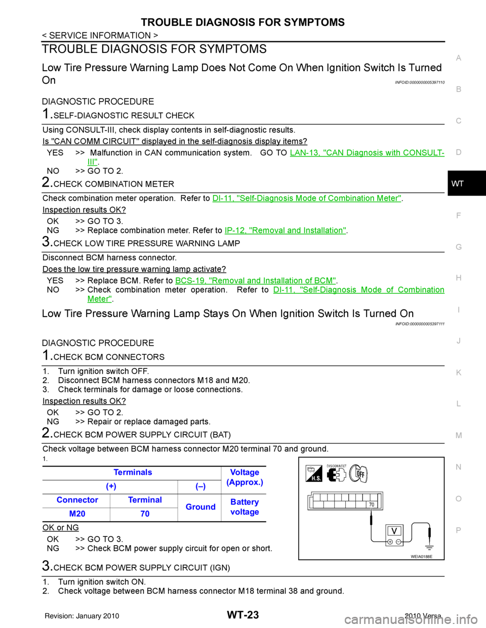
Check voltage between BCM harness connector M20 terminal 70 and ground.
1.
OK or NG
OK >> GO TO 3.
NG >> Check BCM power supply circuit for open or short.
3.CHECK BCM POWER SUPPLY CIRCUIT (IGN)
1. Turn ignition switch ON.
2. Check voltage between BCM harness connector M18 terminal 38 and ground. Terminals Voltage
(Approx.)
(+) (–)
Connector Terminal GroundBattery
voltage
M20 70
WEIA0188E
Revision: January 20102010 Versa
Page 3712 of 3745

FRONT WIPER AND WASHER SYSTEMWW-7
< SERVICE INFORMATION >
C
DE
F
G H
I
J
L
M A
B
WW
N
O P
AUTO STOP OPERATION
With wiper switch turned OFF, wiper motor will cont inue to operate until wiper arms reach windshield base.
When the wiper arms are not located at base of wi ndshield with wiper switch OFF, ground is supplied
• from IPDM E/R terminal 33
• to front wiper motor terminal 3, in order to continue wiper motor operation at low speed.
When the wiper arms reach base of windshield, front wiper motor terminals 4 and 2 are connected, and
ground is supplied
• to IPDM E/R terminal 38
• through front wiper motor terminals 4 and 2, and
• through grounds E15 and E24.
Then the IPDM E/R sends auto stop operation signal to BCM with CAN communication line.
When the BCM receives auto-stop operation signal, BCM sends wiper stop signal to IPDM E/R with CAN com-
munication line.
IPDM E/R stops wiper motor. Wiper motor wi ll then stop wiper arms at the STOP position.
WASHER OPERATION
When the wiper switch is in front wiper washer positi on, BCM detect front wiper washer signal by BCM combi-
nation switch reading function. Refer to BCS-4, "
System Description" .
Combination switch power is supplied• through combination switch terminal 14
• to washer motor terminal 1.
Ground is supplied• to front washer motor terminal 2
• through combination switch terminal 11, and
• through combination switch terminal 12
• through grounds M57 and M61.
With ground supplied, front washer motor is operated.
When the BCM detects that front washer motor has operated for 0.4 seconds or longer, BCM operates front
wiper motor for low speed.
When the BCM detects washer switch is OFF, low speed operation cycles approximately 2 times and stops.
MIST OPERATION
When the wiper switch is turned to the mist position, wiper low speed operation cycles once and then stops.
For additional information about wiper operation under th is condition, refer to "LOW SPEED WIPER OPERA-
TION" .
If switch is held in mist posit ion, low speed operation continues.
FAIL-SAFE FUNCTION
If an abnormality occurs in CAN communications, IPDM E/ R holds the condition just before fail-safe status is
initiated until ignition switch is turned OFF. (If wipers we re operating in LO just before the initiation of fail-safe
status, they continue to operate in LO until ignition switch is turned OFF.)
COMBINATION SWITCH READING FUNCTION
Refer to BCS-4, "System Description" .
CAN Communication System DescriptionINFOID:0000000005395056
Refer to LAN-7, "System Description".
Revision: January 20102010 Versa