2010 NISSAN LATIO key fob
[x] Cancel search: key fobPage 496 of 3745

BCM (BODY CONTROL MODULE)BCS-7
< SERVICE INFORMATION >
C
DE
F
G H
I
J
L
M A
B
BCS
N
O P
• When CAN communication operation is detected, it switches to CAN communication status.
• When a state of the following switches changes , it switches to CAN communication state:
- Ignition switch
- Key switch (without Intelligent Key)
- Key switch and ignition knob switch (with Intelligent Key)
- Hazard switch
- Door lock/unlock switch (with power door locks)
- Front door switch (LH, RH)
- Rear door switch (LH, RH)
- Back door lock assembly (Hatchback)
- Trunk key cylinder switch (Sedan)
- Trunk lamp switch and trunk release solenoid (Sedan)
- Combination switch (passing, lighting switch 1st position, front fog lamp)
- Keyfob (lock/unlock signal) (with power door locks)
- Front door key cylinder switch LH
• When control performed only by BCM is required by switch, it shifts to CAN communication inactive mode.
• Status of combination switch reading function is changed.
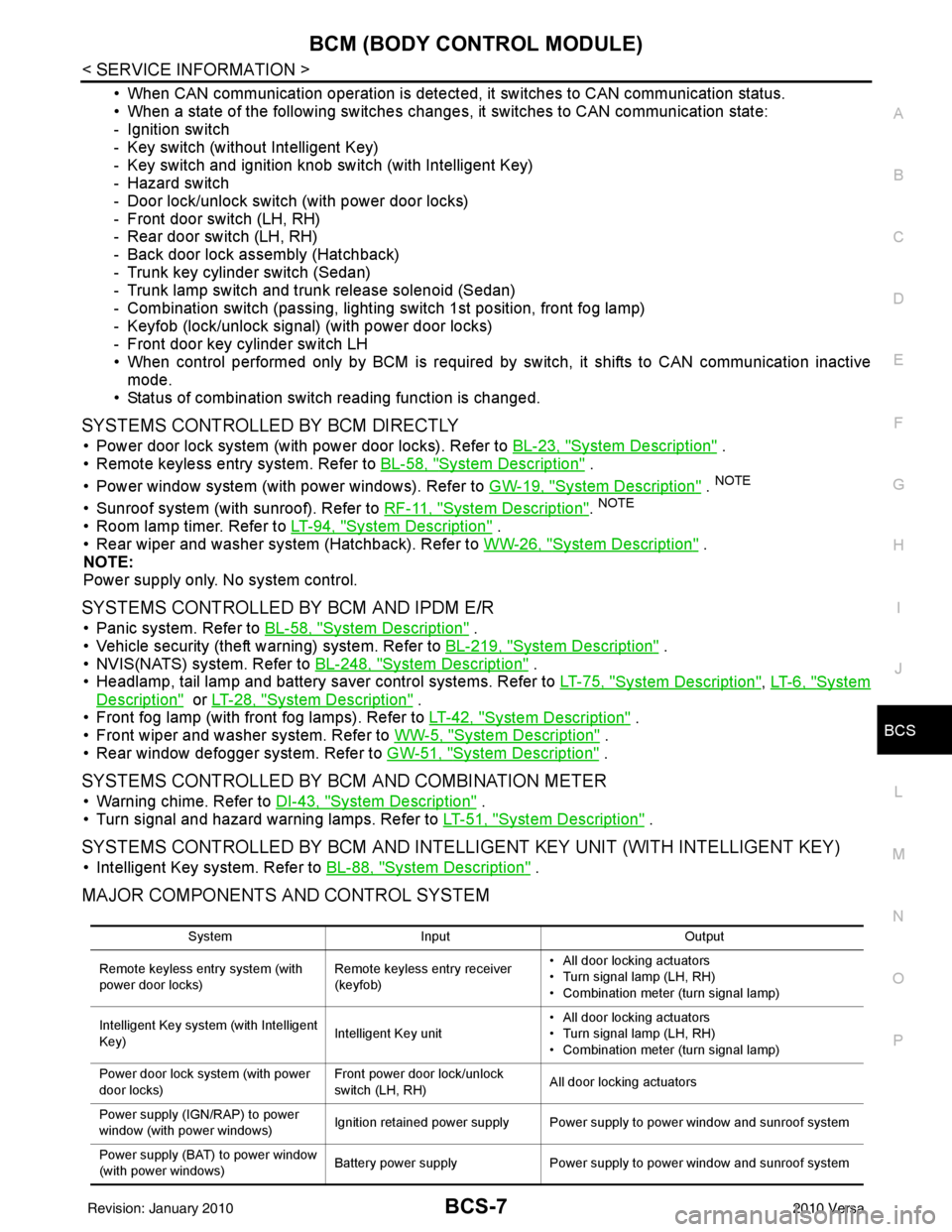
SYSTEMS CONTROLLED BY BCM DIRECTLY
• Power door lock system (with power door locks). Refer to BL-23, "System Description" .
• Remote keyless entry system. Refer to BL-58, "
System Description" .
• Power window system (with power windows). Refer to GW-19, "
System Description" . NOTE
• Sunroof system (with sunroof). Refer to RF-11, "System Description". NOTE
• Room lamp timer. Refer to LT-94, "System Description" .
• Rear wiper and washer system (Hatchback). Refer to WW-26, "
System Description" .
NOTE:
Power supply only. No system control.
SYSTEMS CONTROLLED BY BCM AND IPDM E/R
• Panic system. Refer to BL-58, "System Description" .
• Vehicle security (theft warning) system. Refer to BL-219, "
System Description" .
• NVIS(NATS) system. Refer to BL-248, "
System Description" .
• Headlamp, tail lamp and battery saver control systems. Refer to LT-75, "
System Description", LT- 6 , "System
Description" or LT-28, "System Description" .
• Front fog lamp (with front fog lamps). Refer to LT-42, "
System Description" .
• Front wiper and washer system. Refer to WW-5, "
System Description" .
• Rear window defogger system. Refer to GW-51, "
System Description" .
SYSTEMS CONTROLLED BY BCM AND COMBINATION METER
• Warning chime. Refer to DI-43, "System Description" .
• Turn signal and hazard warning lamps. Refer to LT-51, "
System Description" .
SYSTEMS CONTROLLED BY BCM AND INTELLIGENT KEY UNIT (WITH INTELLIGENT KEY)
• Intelligent Key system. Refer to BL-88, "System Description" .
MAJOR COMPONENTS AND CONTROL SYSTEM
System Input Output
Remote keyless entry system (with
power door locks) Remote keyless entry receiver
(keyfob)• All door locking actuators
• Turn signal lamp (LH, RH)
• Combination meter (turn signal lamp)
Intelligent Key system (with Intelligent
Key) Intelligent Key unit• All door locking actuators
• Turn signal lamp (LH, RH)
• Combination meter (turn signal lamp)
Power door lock system (with power
door locks) Front power door lock/unlock
switch (LH, RH)
All door locking actuators
Power supply (IGN /RAP) to power
window (with power windows) Ignition retained power supply Power supply to power window and sunroof system
Power supply (BAT) to power window
(with power windows) Battery power supply
Power supply to power window and sunroof system
Revision: January 20102010 Versa
Page 497 of 3745

BCS-8
< SERVICE INFORMATION >
BCM (BODY CONTROL MODULE)
CAN Communication System Description
INFOID:0000000005395104
Refer to LAN-7, "System Description".
Panic alarm •Key switch
•KeyfobIPDM E/R
Vehicle security system • All door switches
•Keyfob
• Door lock/unlock switch
• Trunk key cylinder switch (Se-
dan)
• Front door key cylinder switch LH • IPDM/ER
• Security indicator lamp
Battery save r control • Ignition switch
• Combination switch
IPDM E/R
Headlamp Combination switch IPDM E/R
Tail lamp Combination switchIPDM E/R
Front fog lamp (with front fog lamps) Combination switch IPDM E/R
Turn signal lamp Combination switch• Turn signal lamp
• Combination meter
Hazard lamp Hazard switch• Turn signal lamp
• Combination meter
Room lamp timer •Key switch
•Keyfob
• Main power window and door
lock/unlock switch
• Front door switch LH
• All door switch Interior room lamp
Back door switch signal (Hatchback) Back door lock assembly Luggage room lamp
Back door lock signal (Hatchback) Back door lock assembly Back door opener
Trunk lamp switch signal (Sedan) Trunk lamp switch and trunk re-
lease solenoidLuggage room lamp
Trunk lid opener signal (Sedan) Trunk lamp switch and trunk re-
lease solenoid
Trunk lid opener
Key warning chime •Key switch
• Front door switch LHCombination meter (warning buzzer)
Light warning chime • Combination switch
•Key switch
• Front door switch LHCombination meter (warning buzzer)
Seat belt warning chime • Seat belt buckle switch LH
• Ignition switch
Combination meter (warning buzzer)
Front wiper and washer system • Combination switch
• Ignition switchIPDM E/R
Rear window defogger Rear window defogger switch IPDM E/R
Rear wiper and washer system
(Hatchback) • Combination switch
• Ignition switch
Rear wiper motor
A/C switch signal Front air controlECM
Blower fan switch signal Front air controlECM
A/C indicator signal Front air controlA/C indicator
Low tire pressure warning system Remote keyless entry receiver Combination meter System
Input Output
Revision: January 20102010 Versa
Page 502 of 3745

BCM (BODY CONTROL MODULE)BCS-13
< SERVICE INFORMATION >
C
DE
F
G H
I
J
L
M A
B
BCS
N
O P
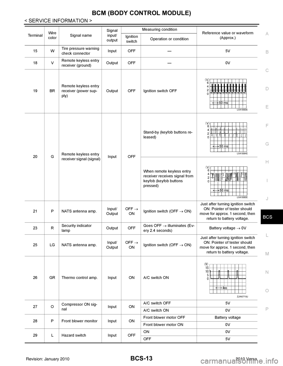
15 W Tire pressure warning
check connector
Input OFF
—5V
18 V Remote keyless entry
receiver (ground) Output OFF
—0V
19 BR Remote keyless entry
receiver (power sup-
ply) Output OFF Ignition switch OFF
20 G Remote keyless entry
receiver signal (signal)
Input OFFStand-by (keyfob buttons re-
leased)
When remote keyless entry
receiver receives signal from
keyfob (keyfob buttons
pressed)
21 P NATS antenna amp. Input/
Output OFF
→
ON Ignition switch (OFF → ON) Just after turning ignition switch
ON: Pointer of tester should
move for approx. 1 second, then
return to battery voltage.
23 R Security indicator
lamp Output OFF
Goes OFF
→ illuminates (Ev-
ery 2.4 seconds) Battery voltage
→ 0V
25 LG NATS antenna amp. Input/
Output OFF
→
ON Ignition switch (OFF → ON) Just after turning ignition switch
ON: Pointer of tester should
move for approx. 1 second, then return to battery voltage.
26 GR Thermo control amp. Input ON A/C switch ON
27 O Compressor ON sig-
nal Input ONA/C switch OFF
5V
A/C switch ON 0V
28 P Front blower monitor Input ON Front blower motor OFF
Battery voltage
Front blower motor ON 0V
29 L Hazard switch Input OFFON
0V
OFF 5V
Te r m i n a l
Wire
color Signal name Signal
input/
output Measuring condition
Reference value or waveform
(Approx.)
Ignition
switch Operation or condition
LIIA1893E
LIIA1894E
LIIA1895E
ZJIA0719J
Revision: January 20102010 Versa
Page 509 of 3745

BCS-20
< SERVICE INFORMATION >
BCM (BODY CONTROL MODULE)
INSTALLATION
Installation is in the reverse order of removal.
CAUTION:
• When replacing BCM, perform “WRITE CONFIGURATION”. Refer to BCS-19, "
Configuration".
• When replacing BCM, perform the system initializati on (NATS). Refer to the CONSULT-III operation
manual for the initialization procedure.
• When replacing BCM, if new BCM does not come wi th key fobs attached, all existing key fobs must
be re-registered. Refer to the CONSULT-III oper ation manual for the initialization procedure.
Revision: January 20102010 Versa
Page 510 of 3745

BL-1
BODY
C
DE
F
G H
J
K L
M
SECTION BL
A
B
BL
N
O P
CONTENTS
BODY, LOCK & SECURITY SYSTEM
SERVICE INFORMATION .. ..........................4
PRECAUTIONS .............................................. .....4
Precaution for Supplemental Restraint System
(SRS) "AIR BAG" and "SEAT BELT PRE-TEN-
SIONER" ............................................................. ......
4
Precaution Necessary for Steering Wheel Rota-
tion After Battery Disconnect ............................... ......
4
Precaution for Procedure without Cowl Top Cover ......5
Precaution for Work ..................................................5
PREPARATION ...................................................6
Special Service Tool ........................................... ......6
Commercial Service Tool ..........................................6
SQUEAK AND RATTLE TROUBLE DIAG-
NOSES ................................................................
7
Work Flow ........................................................... ......7
Generic Squeak and Rattle Troubleshooting ............9
Diagnostic Worksheet .............................................11
HOOD .................................................................13
Fitting Adjustment ............................................... ....13
Removal and Installation .........................................14
Removal and Installation of Hood Lock Control .. ....15
Hood Lock Control Inspection .................................17
RADIATOR CORE SUPPORT ....................... ....19
Removal and Installation .........................................19
FRONT FENDER ................................................21
Removal and Installation .........................................21
POWER DOOR LOCK SYSTEM .................... ....22
Component Parts and Harness Connector Loca-
tion ...................................................................... ....
22
System Description .................................................23
CAN Communication System Description ...............25
Schematic ...............................................................26
Wiring Diagram - D/LOCK - .....................................27
Schematic ...............................................................31
Wiring Diagram - D/LOCK - .....................................32
Terminal and Reference Value for BCM ..................37
Work Flow ............................................................ ....41
CONSULT-III Function (BCM) .................................41
Trouble Diagnosis Symptom Chart ...................... ....43
BCM Power Supply and Ground Circuit Inspection
....
43
Door Switch Check (Hatchback) ..............................44
Door Switch Check (Sedan) ....................................47
Key Switch (Insert) Check .......................................48
Door Lock and Unlock Switch Check ......................49
Front Door Lock Assembly LH (Actuator) Check .....52
Door Lock Actuator Check (Front RH and Rear
LH/RH) ................................................................. ....
53
Front Door Key Cylinder Switch LH Check ..............54
Passenger Select Unlock Relay Circuit Inspection
(With Intelligent Key) ........................................... ....
55
REMOTE KEYLESS ENTRY SYSTEM .............58
Component Parts and Harness Connector Loca-
tion ...........................................................................
58
System Description ..................................................58
CAN Communication System Description ...............60
Schematic ................................................................61
Wiring Diagram - KEYLES - ....................................62
Terminal and Reference Value for BCM ..................65
How to Perform Trouble Diagnosis ...................... ....69
Preliminary Check ...................................................69
CONSULT-III Function (BCM) .................................69
Work Flow ............................................................ ....71
Trouble Diagnosis Symptom Chart ..........................71
Keyfob Battery and Function Check ........................72
ACC Switch Check ..................................................74
Door Switch Check (Hatchback) ..............................74
Door Switch Check (Sedan) ....................................76
Key Switch (Insert) Check .......................................78
Hazard Function Check ...........................................78
Horn Function Check ...............................................79
Interior Lamp and Ignition Keyhole Illumination
Function Check ........................................................
79
Remote Keyless Entry Receiver Check ...................80
Keyfob Function (Lock) Check ............................ ....82
Revision: January 20102010 Versa
Page 511 of 3745

BL-2
Keyfob Function (Unlock) Check ............................82
ID Code Entry Procedure .................................... ...82
Keyfob Battery Replacement ............................... ...85
Removal and Installation of Remote Keyless Entry
Receiver .............................................................. ...
85
INTELLIGENT KEY SYSTEM ............................86
Component Parts and Harness Connector Loca-
tion ....................................................................... ...
86
System Description .................................................88
CAN Communication System Description ..............95
Schematic ............................................................ ...96
Wiring Diagram - I/KEY - ..................................... ...98
Intelligent Key Unit Har ness Connector Terminal
Layout .................................................................. ..
108
Terminal and Reference Value for Intelligent Key
Unit ........................................................................
108
Steering Lock Solenoid Harness Connector Ter-
minal Layout ..........................................................
110
Terminal and Reference Value for Steering Lock
Solenoid .................................................................
110
Terminal and Reference Value for BCM ................111
Trouble Diagnosis Procedure ................................115
CONSULT-III Functions (INTELLIGENT KEY) ......117
CONSULT-III Application Item ............................. ..117
Trouble Diagnosis Symptom Chart ........................119
CAN Communication System Inspection ...............126
Power Supply and Ground Circuit Inspection ........126
Key Switch (Intelligent Key Unit Input) Check .......127
Key Switch (BCM Input) Check .............................128
Ignition Knob Switch Check ................................. ..129
Door Switch Check (Hatchback) ............................131
Door Switch Check (Sedan) ..................................133
Door Request Switch Check ..................................135
Back Door Request Switch Check (Hatchback) ....137
Trunk Opener Request Switch Check (Sedan) ... ..138
Unlock Sensor Check ............................................140
Intelligent Key Warning Buzzer(s) Check ..............142
Outside Key Antenna (Dri ver Side and Passenger
Side) Check ......................................................... ..
143
Outside Key Antenna (Rear Bumper) Check .........144
Inside Key Antenna Check ....................................146
Steering Lock Solenoid Check ............................ ..147
Key Interlock Solenoid (With M/T) Check ..............149
Ignition Switch Position Check ............................ ..150
Stop Lamp Switch Check (With CVT or A/T) ....... ..150
Stop Lamp Switch Check (With M/T) .....................152
CVT or A/T Shift Selector (Park Position Switch)
Check .................................................................. ..
153
"P-SHIFT" Warning Lamp (With CVT or A/T)
Check ....................................................................
154
"LOCK" Warning Lamp (With M/T) Check .............155
"KEY" Warning Lamp (RED) Check ......................155
"KEY" Warning Lamp (G REEN) Check .................155
Check Warning Chime in Combination Meter ........156
Hazard Function Check .........................................156
Horn Function Check .... .........................................157
Headlamp Function Chec k ....................................157
Intelligent Key Battery Replacement ................... ..158
Remote Keyless Entry Function ............................158
Removal and Installation of Intelligent Key Unit ... .158
DOOR ...............................................................160
Fitting Adjustment ................................................ .160
Removal and Installation .......................................163
FRONT DOOR LOCK ..................................... ..166
Component Parts Location .................................. .166
Removal and Installation .......................................166
REAR DOOR LOCK ....................................... ..169
Component Parts Location .................................. .169
Removal and Installation .......................................169
BACK DOOR LOCK ....................................... ..172
Component Parts and Harness Connector Loca-
tion ....................................................................... .
172
System Description ...............................................172
Wiring Diagram - B/DOOR - ..................................173
Terminal and Reference Value for BCM ...............175
Terminal and Reference Value for Intelligent Key
Unit ....................................................................... .
179
CONSULT-III Function (BCM) ..............................181
Work Flow .............................................................182
Trouble Diagnosis Chart by Symptom ..................182
BCM Power Supply and Ground Circuit Inspection
.
182
Check Back Door Opener Switch Circuit (Without
Intelligent Key or Power Windows) ...................... .
183
Check Back Door Opener Switch Circuit (Without
Intelligent Key, with Power Windows) .................. .
186
Check Back Door Opener Switch Circuit (With In-
telligent Key) ........................................................ .
188
Check Back Door Lock Assembly (Actuator) Cir-
cuit ........................................................................
190
Removal and Installation .......................................192
TRUNK LID ..................................................... ..193
Fitting Adjustment ................................................ .193
Trunk Lid Assembly ..............................................193
Trunk Lid Lock ......................................................194
Trunk Lid Striker ....................................................194
Trunk Lid Stay Disposal ........................................195
TRUNK LID OPENER .......................................196
Component Parts and Harness Connector Loca-
tion ....................................................................... .
196
System Description ...............................................196
Wiring Diagram - TLID - ........................................197
Terminal and Reference Value for BCM ...............199
Terminal and Reference Value for Intelligent Key
Unit ....................................................................... .
203
CONSULT-III Function (BCM) ..............................205
Work Flow .............................................................206
Trouble Diagnosis Chart by Symptom ..................206
BCM Power Supply and Ground Circuit Inspection
.
206
Check Trunk Lid Opener Switch Circuit (Without
Intelligent Key or Power Windows) ...................... .
207
Revision: January 20102010 Versa
Page 515 of 3745

BL-6
< SERVICE INFORMATION >
PREPARATION
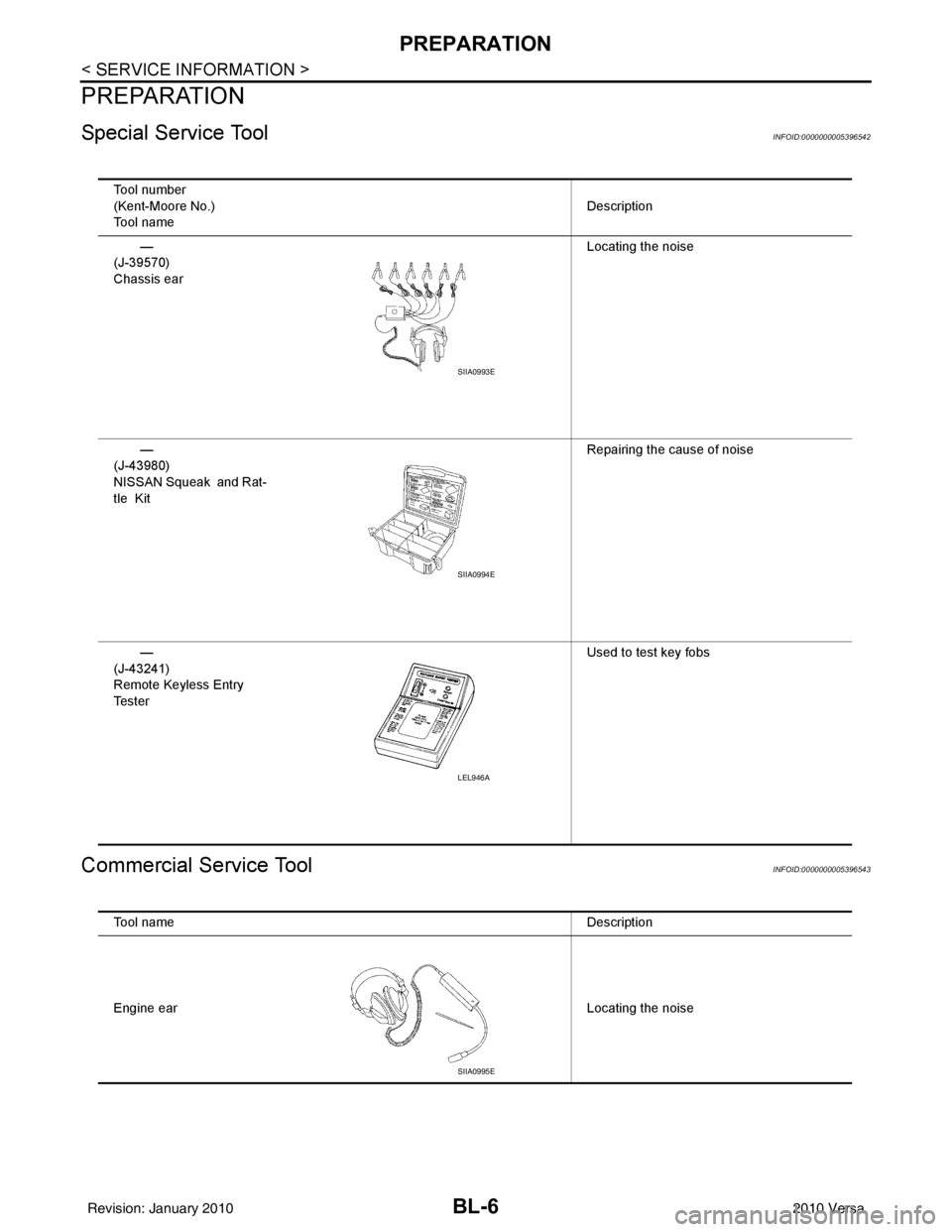
PREPARATION
Special Service ToolINFOID:0000000005396542
Commercial Service ToolINFOID:0000000005396543
Tool number
(Kent-Moore No.)
Tool nameDescription
—
(J-39570)
Chassis ear Locating the noise
—
(J-43980)
NISSAN Squeak and Rat-
tle Kit Repairing the cause of noise
—
(J-43241)
Remote Keyless Entry
Te s t e r Used to test key fobs
SIIA0993E
SIIA0994E
LEL946A
Tool name
Description
Engine ear Locating the noise
SIIA0995E
Revision: January 20102010 Versa
Page 547 of 3745

BL-38
< SERVICE INFORMATION >
POWER DOOR LOCK SYSTEM
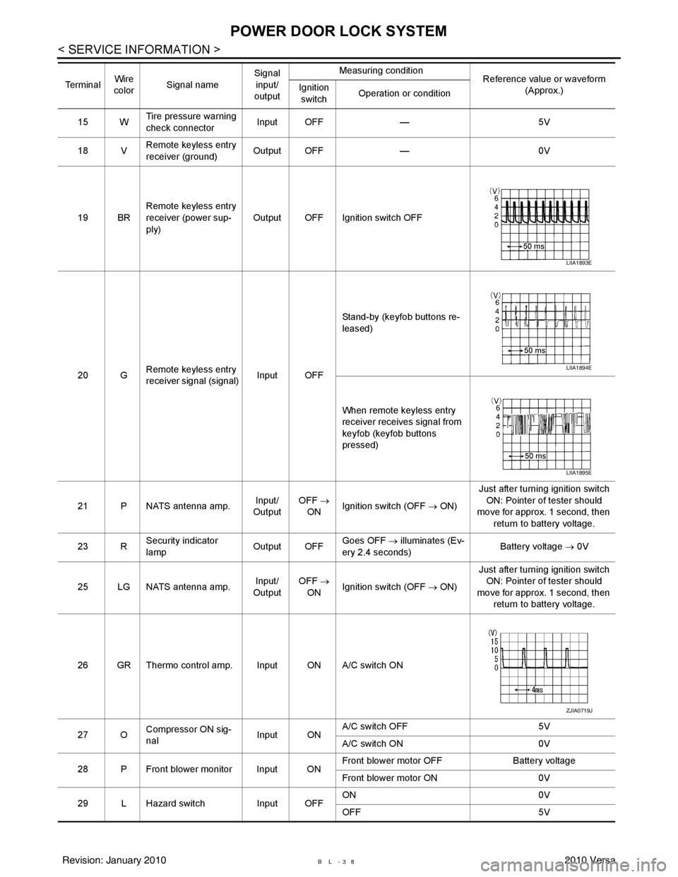
15 WTire pressure warning
check connector
Input OFF
—5V
18 V Remote keyless entry
receiver (ground) Output OFF
—0V
19 BR Remote keyless entry
receiver (power sup-
ply) Output OFF Ignition switch OFF
20 G Remote keyless entry
receiver signal (signal)
Input OFFStand-by (keyfob buttons re-
leased)
When remote keyless entry
receiver receives signal from
keyfob (keyfob buttons
pressed)
21 P NATS antenna amp. Input/
Output OFF
→
ON Ignition switch (OFF
→ ON)Just after turning ignition switch
ON: Pointer of tester should
move for approx. 1 second, then
return to battery voltage.
23 R Security indicator
lamp Output OFF
Goes OFF
→ illuminates (Ev-
ery 2.4 seconds) Battery voltage
→ 0V
25 LG NATS antenna amp. Input/
Output OFF
→
ON Ignition switch (OFF
→ ON)Just after turning ignition switch
ON: Pointer of tester should
move for approx. 1 second, then return to battery voltage.
26 GR Thermo control amp. Input ON A/C switch ON
27 O Compressor ON sig-
nal Input ONA/C switch OFF
5V
A/C switch ON 0V
28 P Front blower monitor Input ON Front blower motor OFF
Battery voltage
Front blower motor ON 0V
29 L Hazard switch Input OFFON
0V
OFF 5V
Te r m i n a l
Wire
color Signal name Signal
input/
output Measuring condition
Reference value or waveform
(Approx.)
Ignition
switch Operation or condition
LIIA1893E
LIIA1894E
LIIA1895E
ZJIA0719J
Revision: January 20102010 Versa