2010 NISSAN LATIO key fob
[x] Cancel search: key fobPage 583 of 3745
BL-74
< SERVICE INFORMATION >
REMOTE KEYLESS ENTRY SYSTEM
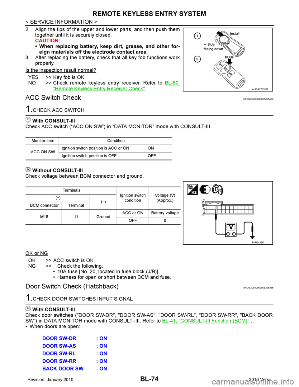
2. Align the tips of the upper and lower parts, and then push themtogether until it is securely closed.
CAUTION:
• When replacing battery, keep dirt, grease, and other for-eign materials off the electrode contact area.
3. After replacing the battery, check that all key fob functions work
properly.
Is the inspection result normal?
YES >> Key fob is OK.
NO >> Check remote keyless entry receiver. Refer to BL-80,
"Remote Keyless Entry Receiver Check".
ACC Switch CheckINFOID:0000000005396585
1.CHECK ACC SWITCH
With CONSULT-III
Check ACC switch (“ACC ON SW”) in “DATA MONITOR” mode with CONSULT-III.
Without CONSULT-III
Check voltage between BCM connector and ground.
OK or NG
OK >> ACC switch is OK.
NG >> Check the following. • 10A fuse [No. 20, located in fuse block (J/B)]
• Harness for open or short between BCM and fuse.
Door Switch Check (Hatchback)INFOID:0000000005396586
1.CHECK DOOR SWITCHES INPUT SIGNAL
With CONSULT-III
Check door switches ("DOOR SW-DR", "DOOR SW-AS", "DOOR SW-RL", "DOOR SW-RR", "BACK DOOR
SW") in DATA MONITOR mode with CONSULT–III. Refer to BL-41, "
CONSULT-III Function (BCM)" .
• When doors are open:
ALKIA1721GB
Monitor item Condition
ACC ON SW Ignition switch position is ACC or ON : ON
Ignition switch position is OFF
: OFF
Te r m i n a l s
Ignition switch
condition Voltage (V)
(Approx.)
(+)
(–)
BCM connector Terminal
M18 11 Ground ACC or ON Battery voltage
OFF 0
PIIB6453E
DOOR SW-DR : ON
DOOR SW-AS : ON
DOOR SW-RL : ON
DOOR SW-RR : ON
BACK DOOR SW : ON
Revision: January 20102010 Versa
Page 589 of 3745
BL-80
< SERVICE INFORMATION >
REMOTE KEYLESS ENTRY SYSTEM
Remote Keyless Entry Receiver Check
INFOID:0000000005396592
1.CHECK REMOTE KEYLESS ENTRY RECEIVER OUTPUT SIGNAL
1. Turn ignition switch OFF.
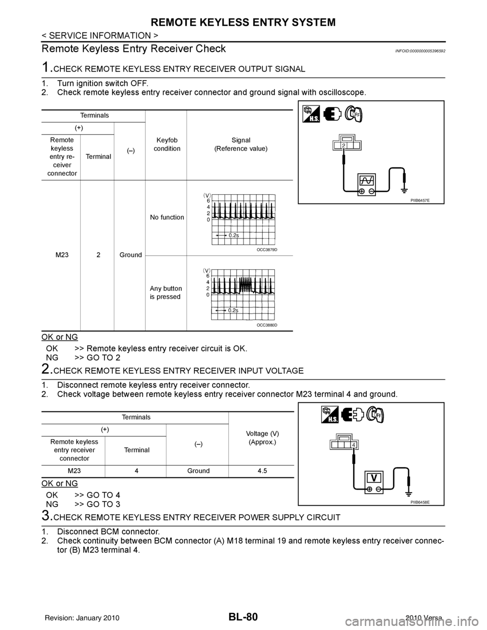
2. Check remote keyless entry receiver connector and ground signal with oscilloscope.
OK or NG
OK >> Remote keyless entry receiver circuit is OK.
NG >> GO TO 2
2.CHECK REMOTE KEYLESS ENTRY RECEIVER INPUT VOLTAGE
1. Disconnect remote keyless entry receiver connector.
2. Check voltage between remote keyless entry receiver connector M23 terminal 4 and ground.
OK or NG
OK >> GO TO 4
NG >> GO TO 3
3.CHECK REMOTE KEYLE SS ENTRY RECEIVER POWER SUPPLY CIRCUIT
1. Disconnect BCM connector.
2. Check continuity between BCM connector (A) M18 terminal 19 and remote keyless entry receiver connec- tor (B) M23 terminal 4.
Te r m i n a l s
Keyfob
condition Signal
(Reference value)
(+)
(–)
Remote
keyless
entry re- ceiver
connector Te r m i n a l
M23 2 Ground No function
Any button
is pressed
PIIB6457E
OCC3879D
OCC3880D
Te r m i n a l s Voltage (V)(Approx.)
(+)
(–)
Remote keyless
entry receiver connector Te r m i n a l
M23 4Ground 4.5
PIIB6458E
Revision: January 20102010 Versa
Page 591 of 3745
BL-82
< SERVICE INFORMATION >
REMOTE KEYLESS ENTRY SYSTEM
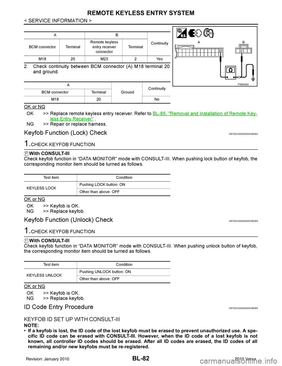
2. Check continuity between BCM connector (A) M18 terminal 20and ground.
OK or NG
OK >> Replace remote keyless entry receiver. Refer to BL-85, "Removal and Installation of Remote Key-
less Entry Receiver" .
NG >> Repair or replace harness.
Keyfob Function (Lock) CheckINFOID:0000000005396593
1.CHECK KEYFOB FUNCTION
With CONSULT-III
Check keyfob function in “DATA MONITOR” mode with CO NSULT-III. When pushing lock button of keyfob, the
corresponding monitor item should be turned as follows.
OK or NG
OK >> Keyfob is OK.
NG >> Replace keyfob.
Keyfob Function (Unlock) CheckINFOID:0000000005396594
1.CHECK KEYFOB FUNCTION
With CONSULT-III
Check keyfob function in “DATA MONITOR” mode with CONSULT-III. When pushing unlock button of keyfob,
the corresponding monitor item should be turned as follows.
OK or NG
OK >> Keyfob is OK.
NG >> Replace keyfob.
ID Code Entry ProcedureINFOID:0000000005396595
KEYFOB ID SET UP WITH CONSULT-III
NOTE:
• If a keyfob is lost, the ID code of the lost keyfob must be erased to prevent unauthorized use. A spe-
cific ID code can be erased with CONSULT-III. Ho wever, when the ID code of a lost keyfob is not
known, all controller ID codes should be erased. After all ID codes are erased, the ID codes of all
remaining and/or new keyfobs must be re-registered.
AB
Continuity
BCM connector Terminal Remote keyless
entry receiver
connector Te r m i n a l
M18 20M23 2Yes
A GroundContinuity
BCM connector Terminal
M18 20 No
PIIB6462E
Test item Condition
KEYLESS LOCK Pushing LOCK button: ON
Other than above: OFF
Test item
Condition
KEYLESS UNLOCK Pushing UNLOCK button: ON
Other than above: OFF
Revision: January 20102010 Versa
Page 592 of 3745

REMOTE KEYLESS ENTRY SYSTEMBL-83
< SERVICE INFORMATION >
C
DE
F
G H
J
K L
M A
B
BL
N
O P
• When registering an addi tional keyfob, the existing ID codes in memory may or may not be erased. If
five ID codes are stored in memory , when an additional code is registered, only the oldest code is
erased. If less than five ID codes are stored in memory, when an additional ID code is registered, the
new ID code is added and no ID codes are erased.
• Entry of maximum five ID codes is allowed. When more than five ID codes are entered, the oldest ID
code will be erased.
• Even if same ID code that is already in the memo ry is input, the same ID code can be entered. The
code is counted as an additional code.
1. Touch “MULTI REMOTE ENT”.
2. Touch “WORK SUPPORT”.
3. The items are shown on the figure can be set up. • “REMO CONT ID CONFIR”
Use this mode to confirm if a keyfob ID code is registered or not.
• “REMO CONT ID REGIST” Use this mode to register a keyfob ID code.
NOTE:
Register the ID code when keyfob or BCM is replaced, or when additional keyfob is required.
• “REMO CONT ID ERASUR”
Use this mode to erase a keyfob ID code.
Revision: January 20102010 Versa
Page 593 of 3745
BL-84
< SERVICE INFORMATION >
REMOTE KEYLESS ENTRY SYSTEM
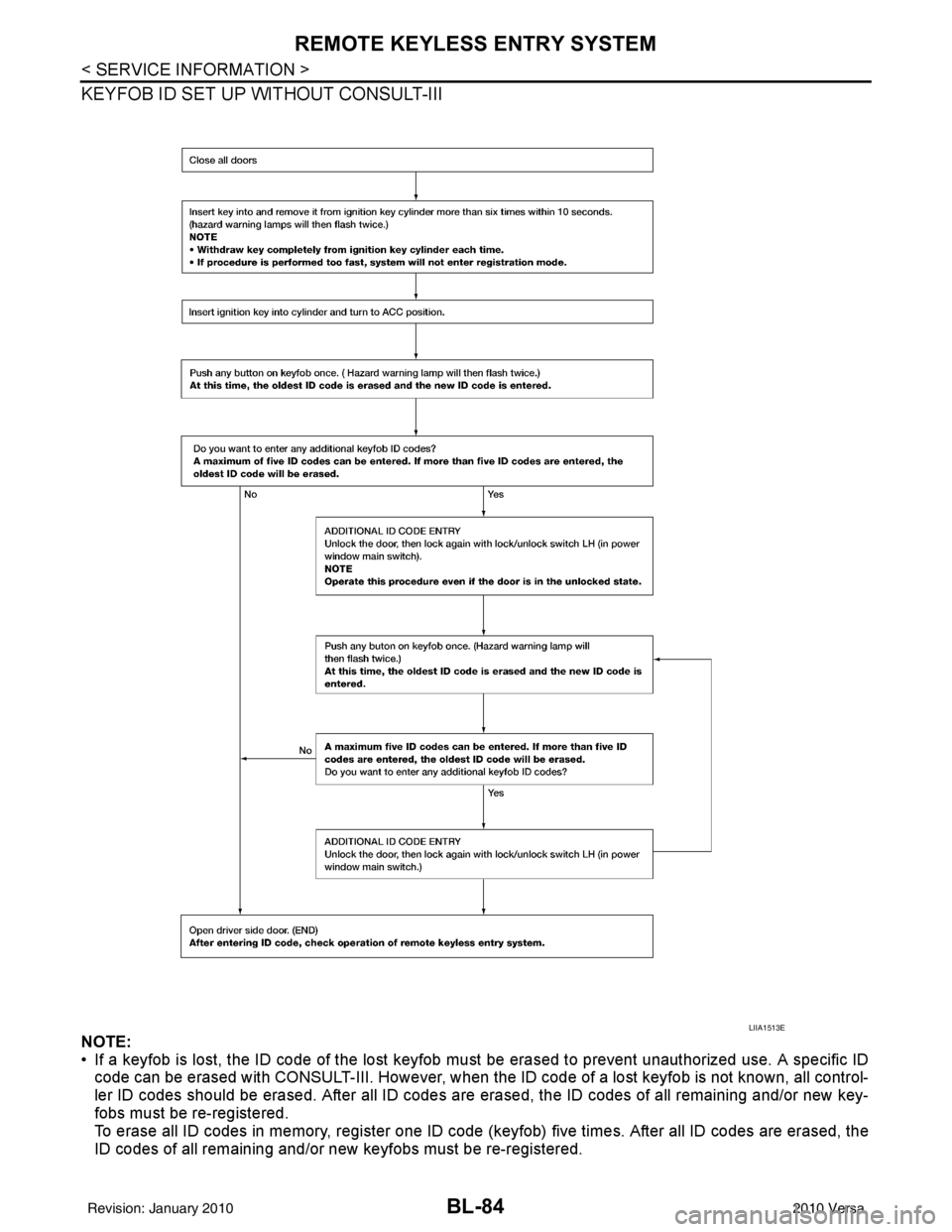
KEYFOB ID SET UP WITHOUT CONSULT-III
NOTE:
• If a keyfob is lost, the ID code of the lost keyfob must be erased to prevent unauthorized use. A specific ID
code can be erased with CONSULT-III. However, when the ID code of a lost keyfob is not known, all control-
ler ID codes should be erased. After all ID codes are erased, the ID codes of all remaining and/or new key-
fobs must be re-registered.
To erase all ID codes in memory, register one ID code (keyfob) five times. After all ID codes are erased, the
ID codes of all remaining and/or new keyfobs must be re-registered.
LIIA1513E
Revision: January 20102010 Versa
Page 594 of 3745
REMOTE KEYLESS ENTRY SYSTEMBL-85
< SERVICE INFORMATION >
C
DE
F
G H
J
K L
M A
B
BL
N
O P
• When registering an additional keyfob, the existing ID codes in memory may or may not be erased. If five ID
codes are stored in memory, when an additional code is registered, only the oldest code is erased. If less
than five ID codes are stored in memory, when an additional ID code is registered, the new ID code is added
and no ID codes are erased.
• If you need to activate more than two additional new keyfobs, repeat the procedure “Additional ID code
entry” for each new keyfob.
• Entry of maximum five ID codes is allowed. When mo re than five ID codes are entered, the oldest ID code
will be erased.
• Even if same ID code that is already in the memory is input, the same ID code can be entered. The code is
counted as an additional code.
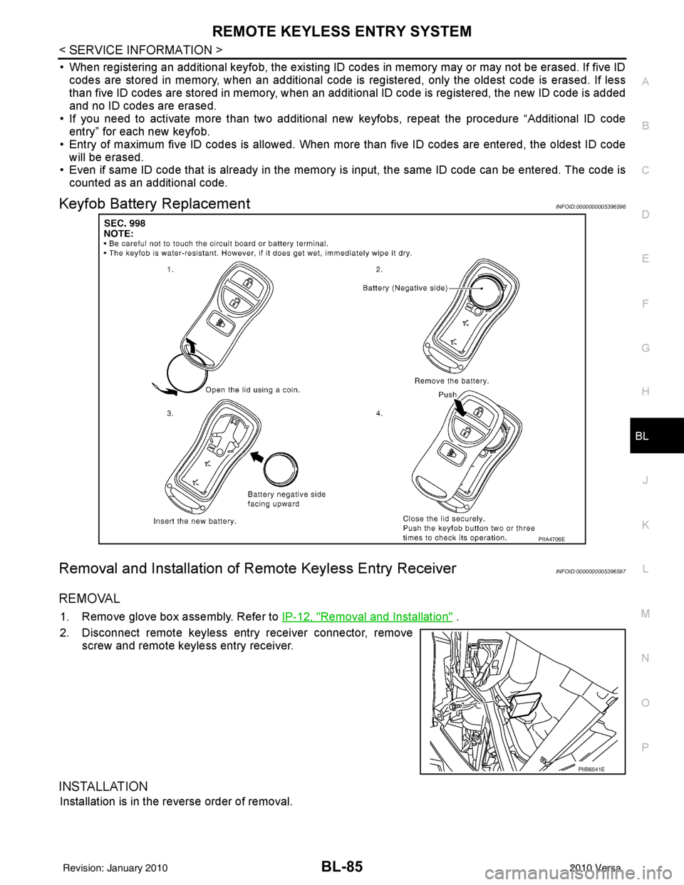
Keyfob Battery ReplacementINFOID:0000000005396596
Removal and Installation of Re mote Keyless Entry ReceiverINFOID:0000000005396597
REMOVAL
1. Remove glove box assembly. Refer to IP-12, "Removal and Installation" .
2. Disconnect remote keyless entry receiver connector, remove screw and remote keyless entry receiver.
INSTALLATION
Installation is in the reverse order of removal.
PIIA4706E
PIIB6541E
Revision: January 20102010 Versa
Page 599 of 3745

BL-90
< SERVICE INFORMATION >
INTELLIGENT KEY SYSTEM
* : Hatchback
** : Sedan
KEY REMINDER FUNCTION
Key reminder functions have the following 2 functions.
CAUTION:
• The above function operates when the Intelligent Key is inside the vehicle. However, there may be
times when the Intelligent Key cannot be detected, an d this function will not operate when the Intelli-
gent Key is on the instrument panel, rear parcel shelf or in the glove box. Also, this system some-
times does not operate if the Intelligent Key is in the door pocket of an open door.
List of Operation Related Parts
Parts marked with × are the parts related to operation
REMOTE KEYLESS ENTRY FUNCTIONS
The Intelligent Key has the same functions as the remote keyless entry system. T herefore, it can be used in
the same manner as the keyfob by operating the door lock/unlock button.
Door lock open function
Intelligent Key
Key switch
Ignition knob switch
Door switch
Back door lock assembly (back door switch)
*
Request switch (driver, passenger, back)
Door lock actuator
Inside key antenna
Outside key antenna
Intelligent Key warning buzzer (front door LH)
Intelligent Key warning buzzer (trunk)
**
Intelligent Key unit
CAN communication system
BCM
Hazard warning lamp
Door lock/unlock function by request switch ××××××××××
Door lock/unlock function by mechanical key ××
Hazard and buzzer reminder function ××××××
Auto door lock function ×××× × ×××
Key reminder functionOperation condition Operation
Door is open to close Right after all doors are closed under the following conditions.
• Intelligent Key is inside the vehicle
• Any door is opened
• All doors are locked by door lock and unlock switch or door
lock knob • All doors unlock operation
• Sound Intelligent Key warn-
ing buzzer for 3 seconds
Key reminder functions
Intelligent Key
Door switch
Unlock sensor
Door lock actuator
Inside key antenna
Intelligent Key warning buzzer(s)
Intelligent Key unit
CAN communication system
BCM
Any door open to close ×××××××××
Revision: January 20102010 Versa
Page 621 of 3745
BL-112
< SERVICE INFORMATION >
INTELLIGENT KEY SYSTEM
15 WTire pressure warning
check connector
Input OFF
—5V
18 V Remote keyless entry
receiver (ground) Output OFF
—0V
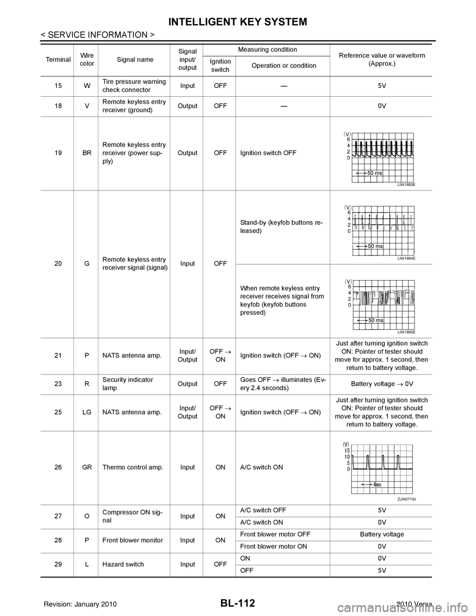
19 BR Remote keyless entry
receiver (power sup-
ply) Output OFF Ignition switch OFF
20 G Remote keyless entry
receiver signal (signal)
Input OFFStand-by (keyfob buttons re-
leased)
When remote keyless entry
receiver receives signal from
keyfob (keyfob buttons
pressed)
21 P NATS antenna amp. Input/
Output OFF
→
ON Ignition switch (OFF
→ ON)Just after turning ignition switch
ON: Pointer of tester should
move for approx. 1 second, then
return to battery voltage.
23 R Security indicator
lamp Output OFF
Goes OFF
→ illuminates (Ev-
ery 2.4 seconds) Battery voltage
→ 0V
25 LG NATS antenna amp. Input/
Output OFF
→
ON Ignition switch (OFF
→ ON)Just after turning ignition switch
ON: Pointer of tester should
move for approx. 1 second, then return to battery voltage.
26 GR Thermo control amp. Input ON A/C switch ON
27 O Compressor ON sig-
nal Input ONA/C switch OFF
5V
A/C switch ON 0V
28 P Front blower monitor Input ON Front blower motor OFF
Battery voltage
Front blower motor ON 0V
29 L Hazard switch Input OFFON
0V
OFF 5V
Te r m i n a l
Wire
color Signal name Signal
input/
output Measuring condition
Reference value or waveform
(Approx.)
Ignition
switch Operation or condition
LIIA1893E
LIIA1894E
LIIA1895E
ZJIA0719J
Revision: January 20102010 Versa