Page 604 of 3745

INTELLIGENT KEY SYSTEMBL-95
< SERVICE INFORMATION >
C
DE
F
G H
J
K L
M A
B
BL
N
O P
CHANGE SETTINGS FUNCTION
The settings for each function c an be changed with the CONSULT-III.
Changing Settings Using CONSULT-III
The settings for the Intelligent Key system func tions can be changed using CONSULT-III (WORK SUPPORT).
Refer to BL-117, "
CONSULT-III Application Item".
NOTE:
Once a function setting is changed, it will remain effective even if the battery is disconnected.
INTELLIGENT KEY REGISTRATION
Intelligent Key-ID registration is performed using the CONSULT-III.
CAUTION:
• After a new Intelligent Key-ID is registered, be sure to check the function.
• When registering an additional Intelligent Key-ID , take any Intelligent Keys already registered and
Intelligent Keys for any other vehicles out of the vehicle before starting.
CONSULT-III can be used to check and delete Intelligent Key-IDs.
For further information, see the CONS ULT-III Operation Manual NATS.
STEERING LOCK SOLENOID REGISTRATION
Steering Lock Solenoid ID Registration
CAUTION:
• The method for registering a steering lock solenoid ID depends on the status of the steering lock
solenoid and Intelligent Key unit (new or old unit).
• After registration is completed, press ignition switch with an Intelligent Key in the vehicle so that it can be turned, and confirm that it cannot be turned even when ignition sw itch is pressed without an
Intelligent Key in the vehicle.
For further information, see the CONSULT-III Operation Manual NATS-IVIS/NVIS.
CAN Communication System DescriptionINFOID:0000000005396600
Refer to LAN-7.
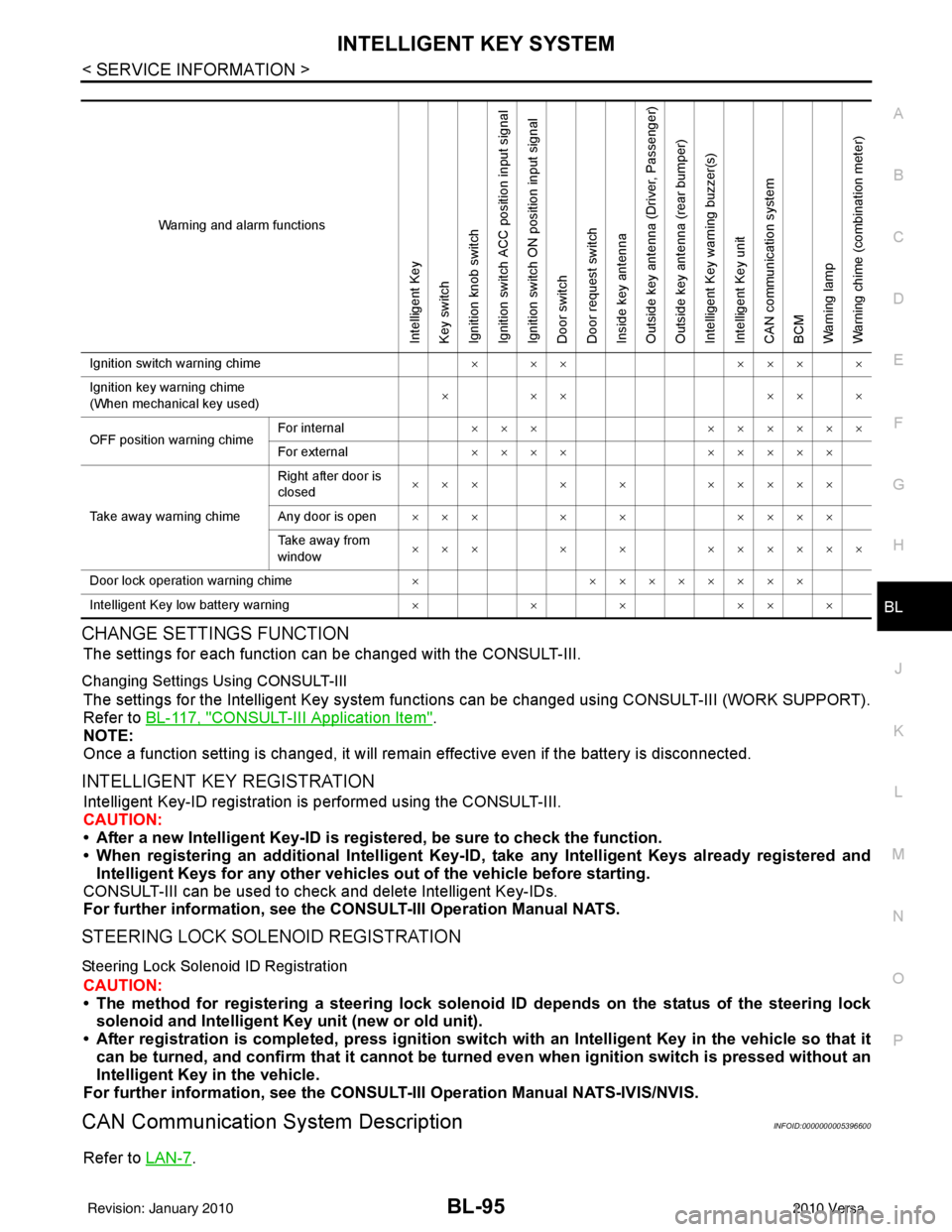
Warning and alarm functions
Intelligent Key
Key switch
Ignition knob switch
Ignition switch ACC position input signal
Ignition switch ON position input signal
Door switch
Door request switch
Inside key antenna
Outside key antenna (Driver, Passenger)
Outside key antenna (rear bumper)
Intelligent Key warning buzzer(s)
Intelligent Key unit
CAN communication system
BCM
Warning lamp
Warning chime (combination meter)
Ignition switch warning chime × ××××× ×
Ignition key warning chime
(When mechanical key used) ×××
×××
OFF position warning chime For internal
××× ××××××
For external ×××× ×××××
Take away warning chime Right after door is
closed
××× × × ×××××
Any door is open ××× × × ××××
Take away from
window ××× × × ××××××
Door lock operation warning chime ×××××××××
Intelligent Key low battery warning ×××× ××
Revision: January 20102010 Versa
Page 635 of 3745

BL-126
< SERVICE INFORMATION >
INTELLIGENT KEY SYSTEM
CAN Communication System Inspection
INFOID:0000000005396612
1.CHECK SELF-DIAGNOSTIC RESULTS
With CONSULT-III• Connect CONSULT-III, and turn ignition switch ON.
• Touch “INTELLIGENT KEY” on “SELECT SYSTEM” screen.
• Touch “SELF-DIAG RESULTS” on “SELECT DIAG MODE” screen.
• Check display content in self-diagnostic results.
OK or NG
NO DTC IS DETECT ED>> Inspection End.
CAN COMM [U1000]>> After printing “SELF-DIAGNOSI S RESULTS”, go to “CAN SYSTEM”. Refer to LAN-
17, "Trouble Diagnosis Flow Chart".
CAN COMM2 [U1010] >> Replace Intelligent Key unit. Refer to BL-158, "
Removal and Installation of Intelli-
gent Key Unit".
Power Supply and Ground Circuit InspectionINFOID:0000000005396613
1.CHECK POWER SUPPLY CIRCUIT
1. Turn ignition switch OFF.
2. Disconnect Intelligent Key unit connector.
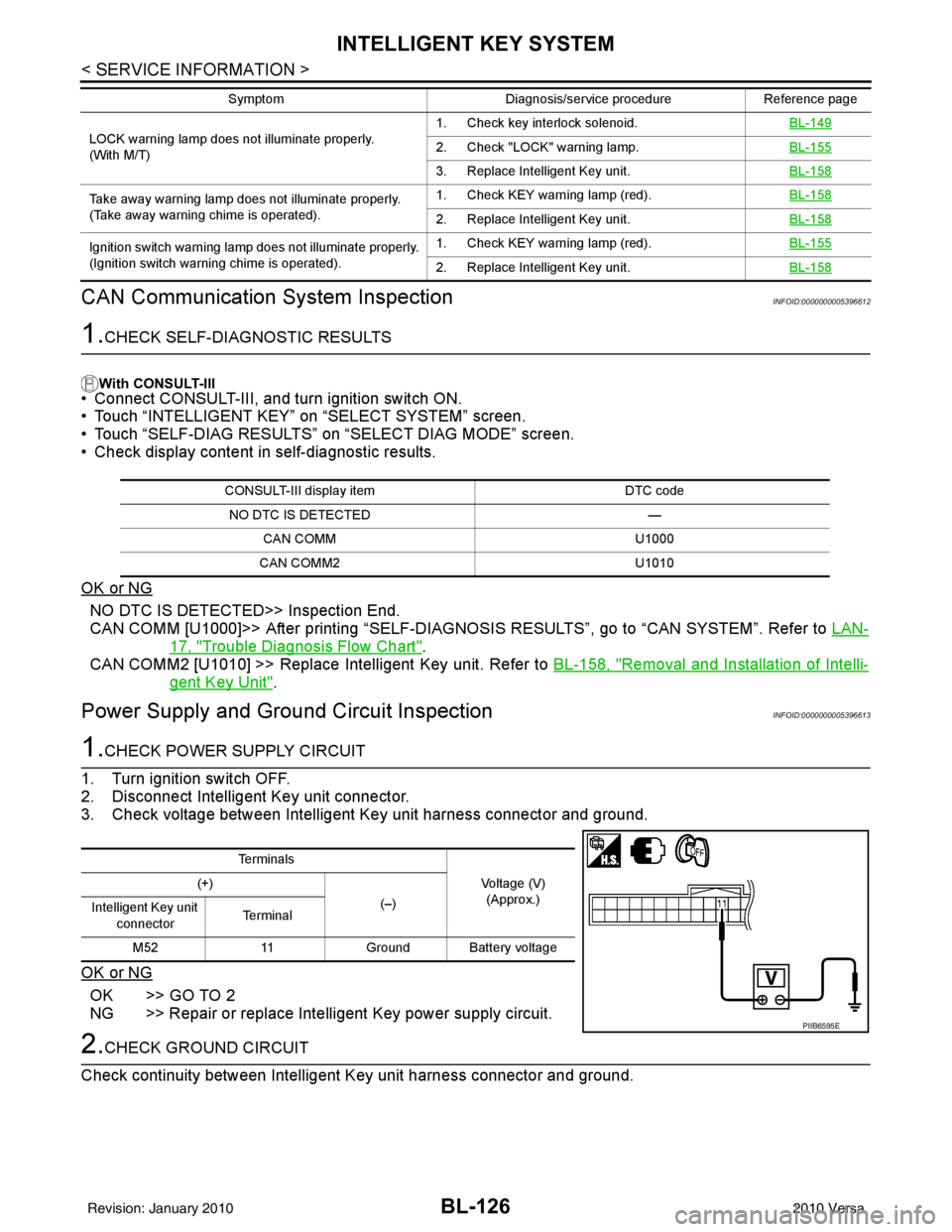
3. Check voltage between Intelligent Key unit harness connector and ground.
OK or NG
OK >> GO TO 2
NG >> Repair or replace Intelligent Key power supply circuit.
2.CHECK GROUND CIRCUIT
Check continuity between Intelligent Key unit harness connector and ground.
LOCK warning lamp does not illuminate properly.
(With M/T) 1. Check key interlock solenoid.
BL-1492. Check "LOCK" warning lamp.BL-155
3. Replace Intelligent Key unit.BL-158
Take away warning lamp does not illuminate properly.
(Take away warning chime is operated).1. Check KEY warning lamp (red).
BL-158
2. Replace Intelligent Key unit.BL-158
Ignition switch warning lamp does not illuminate properly.
(Ignition switch warning chime is operated).1. Check KEY warning lamp (red).
BL-155
2. Replace Intelligent Key unit.BL-158
SymptomDiagnosis/service procedureReference page
CONSULT-III display item DTC code
NO DTC IS DETECTED —
CAN COMM U1000
CAN COMM2 U1010
Te r m i n a l s
Voltage (V)(Approx.)
(+)
(–)
Intelligent Key unit
connector Te r m i n a l
M52 11Ground Battery voltage
PIIB6595E
Revision: January 20102010 Versa
Page 730 of 3745
VEHICLE SECURITY (THEFT WARNING) SYSTEMBL-221
< SERVICE INFORMATION >
C
DE
F
G H
J
K L
M A
B
BL
N
O P
• from IPDM E/R terminal 45
• to horn relay terminal 1.
The headlamp flashes and the horn sounds intermittently.
The alarm automatically turns off after 25 seconds or when BCM receives any signal from keyfob or Intelligent
Key.
CAN Communication System DescriptionINFOID:0000000005396684
Refer to LAN-7.
Revision: January 20102010 Versa
Page 899 of 3745
CAN COMMUNICATIONBRC-9
< SERVICE INFORMATION > [ABS]
C
D
E
G H
I
J
K L
M A
B
BRC
N
O P
CAN COMMUNICATION
System DescriptionINFOID:0000000005397031
Refer to LAN-7, "System Description".
Revision: January 20102010 Versa
Page 920 of 3745
BRC-30
< SERVICE INFORMATION >[ABS]
TROUBLE DIAGNOSIS FOR
SELF-DIAGNOSTIC ITEMS
OK or NG
OK >> Check the battery for loose terminals, low voltage, etc. Repair as necessary.
NG >> Repair the circuit.
CAN Communication System InspectionINFOID:0000000005397045
INSPECTION PROCEDURE
1.CHECK CONNECTOR
1. Turn ignition switch OFF, disconnect the ABS actuat or and electric unit (control unit) connector and check
the terminals for deformation, disconnection, looseness, and so on. If there is a malfunction, repair or
replace the terminal.
2. Reconnect connector to perform self-diagnosis.
Is "CAN COMM CIRCUIT" displayed in self-diagnosis display items?
YES >> Print out the self-diagnostic results, and refer to LAN-17, "Trouble Diagnosis Flow Chart".
NO >> Connector terminal is loose, damaged, open, or shorted. Ground
1
—Continuity should exist.
4
Revision: January 20102010 Versa
Page 922 of 3745
![NISSAN LATIO 2010 Service Repair Manual BRC-32
< SERVICE INFORMATION >[ABS]
TROUBLE DIAGNOSES FOR SYMPTOMS
2. Drive vehicle and check brake operation.
NOTE:
• Stopping distance may be longer than vehicles without ABS when road condition NISSAN LATIO 2010 Service Repair Manual BRC-32
< SERVICE INFORMATION >[ABS]
TROUBLE DIAGNOSES FOR SYMPTOMS
2. Drive vehicle and check brake operation.
NOTE:
• Stopping distance may be longer than vehicles without ABS when road condition](/manual-img/5/57358/w960_57358-921.png)
BRC-32
< SERVICE INFORMATION >[ABS]
TROUBLE DIAGNOSES FOR SYMPTOMS
2. Drive vehicle and check brake operation.
NOTE:
• Stopping distance may be longer than vehicles without ABS when road condition is slippery.
• Driving the vehicle with the ABS actuator and elec tric unit (control unit) disconnected may induce DTCs
in electrical control units using CAN communication. After the inspection, clear all DTCs. Refer to LAN-
7, "System Description".
OK or NG
OK >> GO TO 4.
NG >> Perform Basic Inspection. Refer to BRC-18, "
Basic Inspection".
4.CHECK WHEEL SENSORS
Check the following.
• Wheel sensor mounting for looseness
• Wheel sensors for physical damage
• Wheel sensor connectors for terminal damage or loose connections
• Sensor rotor and mount for physical damage
OK or NG
OK >> Check ABS actuator and electric unit (contro l unit) connector terminals for deformation, discon-
nection, looseness or damage. Reconnect ABS act uator and electric unit (control unit) harness
connector. Then retest.
NG >> Repair or replace as necessary.
Long Stopping DistanceINFOID:0000000005397048
1.CHECK BASE BRAKING SYSTEM PERFORMANCE
1. Disable ABS by disconnecting ABS actuator and electric unit (control unit) connector.
2. Drive vehicle and check brake operation. NOTE:
• Stopping distance may be longer than vehicles without ABS when road condition is slippery.
• Driving the vehicle with the ABS actuator and elec tric unit (control unit) disconnected may induce DTCs
in electrical control units using CAN communication. After the inspection, clear all DTCs. Refer to LAN-
7, "System Description".
OK or NG
OK >> Go to BRC-31, "ABS Works Frequently".
NG >> Perform Basic Inspection. Refer to BRC-18, "
Basic Inspection".
ABS Does Not WorkINFOID:0000000005397049
CAUTION:
The ABS does not operate when the vehicle speed is 10 km/h (6 MPH) or less.
1.CHECK WARNING LAMP ACTIVATION
Turn ignition switch ON and check for warning lamp activation.
• Warning lamp should activate for approximately 2 seconds after turning the ignition switch ON.
OK or NG
OK >> Carry out self-diagnosis. Refer to BRC-20, "CONSULT-III Function (ABS)".
NG >> Go to BRC-18, "
Basic Inspection".
Pedal Vibration or ABS Operation NoiseINFOID:0000000005397050
NOTE:
During ABS activation, pedal vibration may be felt and a noise may be heard. This is normal and does not indi-
cate a malfunction.
1.CHECK SYMPTOM
1. Apply brake.
2. Start engine.
Does the symptom occur only when engine is started?
YES >> Carry out self-diagnosis. Refer to BRC-20, "CONSULT-III Function (ABS)".
Revision: January 20102010 Versa
Page 936 of 3745
BRC-46
< SERVICE INFORMATION >[VDC/TCS/ABS]
CAN COMMUNICATION
CAN COMMUNICATION
System DescriptionINFOID:0000000005612150
Refer to
LAN-7, "System Description".
Revision: January 20102010 Versa
Page 969 of 3745
![NISSAN LATIO 2010 Service Repair Manual TROUBLE DIAGNOSIS FOR SELF-DIAGNOSTIC ITEMS
BRC-79
< SERVICE INFORMATION > [VDC/TCS/ABS]
C
D
E
G H
I
J
K L
M A
B
BRC
N
O P
Check the self-diagnosis results.
Is the above displayed in the self-diagnosi NISSAN LATIO 2010 Service Repair Manual TROUBLE DIAGNOSIS FOR SELF-DIAGNOSTIC ITEMS
BRC-79
< SERVICE INFORMATION > [VDC/TCS/ABS]
C
D
E
G H
I
J
K L
M A
B
BRC
N
O P
Check the self-diagnosis results.
Is the above displayed in the self-diagnosi](/manual-img/5/57358/w960_57358-968.png)
TROUBLE DIAGNOSIS FOR SELF-DIAGNOSTIC ITEMS
BRC-79
< SERVICE INFORMATION > [VDC/TCS/ABS]
C
D
E
G H
I
J
K L
M A
B
BRC
N
O P
Check the self-diagnosis results.
Is the above displayed in the self-diagnosis display items?
YES >> GO TO 2.
NO >> Inspection End.
2.CONNECTOR INSPECTION
1. Disconnect the ABS actuator and el ectric unit (control unit) and brake fluid level switch connectors.
2. Check the terminals for deformation, disconnection, looseness or damage.
OK or NG
OK >> GO TO 3.
NG >> Repair or replace as necessary.
3.CHECK TRANSMISSION RANGE SWITCH
Perform transmission range switch inspection. Refer to AT-94, "
Component Inspection" (with A/T) or CVT-65,
"Component Inspection" (with CVT).
Is the inspection result normal?
YES >> Replace ABS actuator and electr ic unit (control unit). Refer to BRC-89, "Removal and Installa-
tion".
NO >> Repair or replace malfunctioning components.
CAN Communication System InspectionINFOID:0000000005612171
INSPECTION PROCEDURE
1.SELF-DIAGNOSIS RESULT CHECK
Check the self-diagnosis results.
Is the above displayed in the self-diagnosis display items?
YES >> GO TO 2.
NO >> Inspection End.
2.CHECK CONNECTOR
1. Disconnect the ABS actuator and electric unit (control unit) connector, and check the terminals for defor- mation, disconnection, looseness, and so on. If there is a malfunction, repair or replace the terminals.
2. Reconnect connector to perform self-diagnosis. Refer to BRC-60, "
CONSULT-III Function (ABS)".
Is
“CAN COMM CIRCUIT” displayed in the self-diagnosis display items?
YES >> Refer to LAN-17, "Trouble Diagnosis Flow Chart".
NO >> Connector terminal connection is loose, damaged, open, or shorted.
Component InspectionINFOID:0000000005612172
VDC OFF SWITCH
Self-diagnosis results
PNP POS SIG
Self-diagnosis results
ST ANG SEN COM CIR CAN COMM CIRCUIT
Revision: January 20102010 Versa