2010 NISSAN LATIO Lan system
[x] Cancel search: Lan systemPage 48 of 3745

A/T CONTROL SYSTEMAT-31
< SERVICE INFORMATION >
DE
F
G H
I
J
K L
M A
B
AT
N
O P
CONTROL SYSTEM DIAGRAM
CAN CommunicationINFOID:0000000005397222
SYSTEM DESCRIPTION
CAN (Controller Area Network) is a serial communication line for real time application. It is an on-vehicle mul-
tiplex communication line with high data communication speed and excellent error detection ability. Many elec-
tronic control units are equipped onto a vehicle, and each control unit shares information and links with other
control units during operation (not independent). In CAN communication, control units are connected with 2
communication lines (CAN H line, CAN L line) allowing a high rate of information transmission with less wiring.
Each control unit transmits/receives data but selectively reads required data only. For details, refer to LAN-7,
"System Description".
Input/Output Signal of TCMINFOID:0000000005397223
JSDIA1518GB
Control itemLine
pressure control Veh icl e
speed
control Shift
control Lock-up
control Engine
brake
control Fail-safe
function Self-diag-
nostics
function
Input Accelerator pedal position signal
(*5)XXXXX(*3) XX
Output speed sensor X X X X X (*3) X X
Vehicle speed signal (*1) X (*1) X (*1) X (*1) X X
Closed throttle position signal
(*5)(*2) X (*2) X X X(*4) X
Wide open throttle position signal
(*5)(*2) X (*2) X (*4) X
Input speed sensor X XXX X
Engine speed signal XXX X
Transmission range sw itch XXXXX(*3) X(*4) X
Stop lamp switch signal
(*5)XX ( *4 ) X
A/T fluid temperature sensors
(*5)XXXX XX
Overdrive control switch signal
(*5)XXXX (*4) X
TCM power supply voltage signal X XX X
Revision: January 20102010 Versa
Page 53 of 3745
AT-36
< SERVICE INFORMATION >
A/T CONTROL SYSTEM
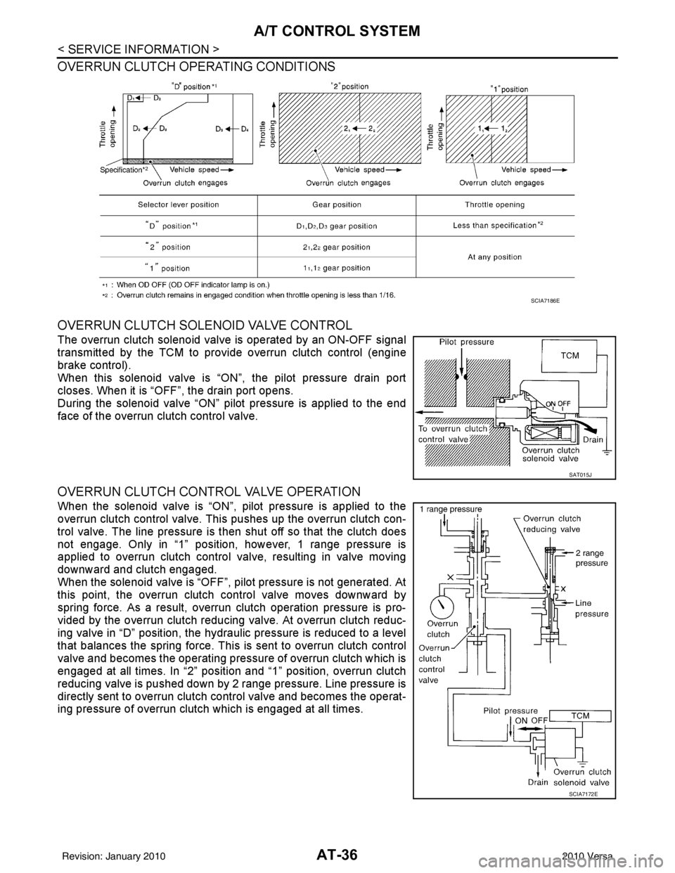
OVERRUN CLUTCH OPERATING CONDITIONS
OVERRUN CLUTCH SOLENOID VALVE CONTROL
The overrun clutch solenoid valve is operated by an ON-OFF signal
transmitted by the TCM to provide overrun clutch control (engine
brake control).
When this solenoid valve is “ON”, the pilot pressure drain port
closes. When it is “OFF”, the drain port opens.
During the solenoid valve “ON” pilot pressure is applied to the end
face of the overrun clutch control valve.
OVERRUN CLUTCH CONTROL VALVE OPERATION
When the solenoid valve is “ON”, pilot pressure is applied to the
overrun clutch control valve. This pushes up the overrun clutch con-
trol valve. The line pressure is t hen shut off so that the clutch does
not engage. Only in “1” position, however, 1 range pressure is
applied to overrun clutch control valve, resulting in valve moving
downward and clutch engaged.
When the solenoid valve is “OFF”, pilot pressure is not generated. At
this point, the overrun clutch control valve moves downward by
spring force. As a result, overrun clutch operation pressure is pro-
vided by the overrun clutch reducing valve. At overrun clutch reduc-
ing valve in “D” position, the hydraulic pressure is reduced to a level
that balances the spring force. This is sent to overrun clutch control
valve and becomes the operating pressure of overrun clutch which is
engaged at all times. In “2” position and “1” position, overrun clutch
reducing valve is pushed down by 2 range pressure. Line pressure is
directly sent to overrun clutch control valve and becomes the operat-
ing pressure of overrun clutch which is engaged at all times.
SCIA7186E
SAT015J
SCIA7172E
Revision: January 20102010 Versa
Page 56 of 3745

ON BOARD DIAGNOSTIC (OBD) SYSTEMAT-39
< SERVICE INFORMATION >
DE
F
G H
I
J
K L
M A
B
AT
N
O P
ON BOARD DIAGNOSTIC (OBD) SYSTEM
IntroductionINFOID:0000000005397230
A/T system has two self-diagnostic systems.
The first is emission-related on board diagnostic system (OBD-II) performed by the TCM in combination with
the ECM. The malfunction is indicated by the MIL (malf unction indicator lamp) and is stored as a DTC in the
ECM memory but not the TCM memory.
The second is the TCM original self-diagnosis indicated by the OD OFF indicator lamp. The malfunction is
stored in the TCM memory. The detected items are ov erlapped with OBD-II self-diagnostic items. For detail,
refer to AT-77, "
CONSULT-III Function (TRANSMISSION)" .
OBD-II Function for A/T SystemINFOID:0000000005397231
The ECM provides emission-related on board diagnostic (O BD-II) functions for the A/T system. One function
is to receive a signal from the TCM used with OBD-rela ted parts of the A/T system. The signal is sent to the
ECM when a malfunction occurs in the corresponding OBD-re lated part. The other function is to indicate a
diagnostic result by means of the MIL (malfunction indica tor lamp) on the instrument panel. Sensors, switches
and solenoid valves are used as sensing elements.
The MIL automatically illuminates in One or Two Trip Detection Logic when a malfunction is sensed in relation
to A/T system parts.
One or Two Trip Detection Logic of OBD-IIINFOID:0000000005397232
ONE TRIP DETECTION LOGIC
If a malfunction is sensed during the first test drive, the MIL will illuminate and the malfunction will be stored in
the ECM memory as a DTC. The TCM is not provided with such a memory function.
TWO TRIP DETECTION LOGIC
When a malfunction is sensed during the first test drive, it is stored in the ECM memory as a 1st trip DTC
(diagnostic trouble code) or 1st trip freeze frame data. At this point, the MIL will not illuminate. — 1st trip
If the same malfunction as that experienced during the fi rst test drive is sensed during the second test drive,
the MIL will illuminate. — 2nd trip
The “trip” in the “One or Two Trip Detection Logic” m eans a driving mode in which self-diagnosis is performed
during vehicle operation.
OBD-II Diagnostic Trouble Code (DTC)INFOID:0000000005397233
HOW TO READ DTC AND 1ST TRIP DTC
DTC and 1st trip DTC can be read by the following methods.
( with CONSULT-III or GST) CONSULT-III or GST (Generic Scan Tool) Examples: P0705, P0720 etc.
These DTC are prescribed by SAE J2012.
(CONSULT-III also displays the malfunctioning component or system.)
• 1st trip DTC No. is the same as DTC No.
• Output of the diagnostic trouble code indicates that the indicated circuit has a malfunction. How-
ever, in case of the Mode II and GST, they do not indicate whether the malfunction is still occurring or
occurred in the past and returned to normal.
CONSULT-III can identify them as shown below, therefore, CONS ULT-III (if available) is recom-
mended.
DTC or 1st trip DTC of a malfunction is displayed in SELF-DIAGNOSTIC RESULTS mode for “ENGINE” with
CONSULT-III. Time data indicates how many times the vehicle was driven after the last detection of a DTC.
If the DTC is being detected curr ently, the time data will be “0”.
If a 1st trip DTC is stored in the ECM, the time data will be “1t”.
Freeze Frame Data and 1st Trip Freeze Frame Data
The ECM has a memory function, which stores the driv ing condition such as fuel system status, calculated
load value, engine coolant temperature, short term f uel trim, long term fuel trim, engine speed and vehicle
speed at the moment the ECM detects a malfunction.
Revision: January 20102010 Versa
Page 106 of 3745
U1000 CAN COMM CIRCUITAT-89
< SERVICE INFORMATION >
DE
F
G H
I
J
K L
M A
B
AT
N
O P
Diagnosis ProcedureINFOID:0000000005397258
1.CHECK CAN COMMUNICATION CIRCUIT
With CONSULT-III1. Turn ignition switch ON and start engine.
2. Select “SELF-DIAG RESULTS” mode for “TRANSMISSION” with CONSULT-III.
Is any malfunction of the
“U1000 CAN COMM CIRCUIT” indicated?
YES >> Print out CONSULT-III screen, Go to LAN section. Refer to LAN-26, "CAN System Specification
Chart".
NO >> INSPECTION END
Revision: January 20102010 Versa
Page 497 of 3745

BCS-8
< SERVICE INFORMATION >
BCM (BODY CONTROL MODULE)
CAN Communication System Description
INFOID:0000000005395104
Refer to LAN-7, "System Description".
Panic alarm •Key switch
•KeyfobIPDM E/R
Vehicle security system • All door switches
•Keyfob
• Door lock/unlock switch
• Trunk key cylinder switch (Se-
dan)
• Front door key cylinder switch LH • IPDM/ER
• Security indicator lamp
Battery save r control • Ignition switch
• Combination switch
IPDM E/R
Headlamp Combination switch IPDM E/R
Tail lamp Combination switchIPDM E/R
Front fog lamp (with front fog lamps) Combination switch IPDM E/R
Turn signal lamp Combination switch• Turn signal lamp
• Combination meter
Hazard lamp Hazard switch• Turn signal lamp
• Combination meter
Room lamp timer •Key switch
•Keyfob
• Main power window and door
lock/unlock switch
• Front door switch LH
• All door switch Interior room lamp
Back door switch signal (Hatchback) Back door lock assembly Luggage room lamp
Back door lock signal (Hatchback) Back door lock assembly Back door opener
Trunk lamp switch signal (Sedan) Trunk lamp switch and trunk re-
lease solenoidLuggage room lamp
Trunk lid opener signal (Sedan) Trunk lamp switch and trunk re-
lease solenoid
Trunk lid opener
Key warning chime •Key switch
• Front door switch LHCombination meter (warning buzzer)
Light warning chime • Combination switch
•Key switch
• Front door switch LHCombination meter (warning buzzer)
Seat belt warning chime • Seat belt buckle switch LH
• Ignition switch
Combination meter (warning buzzer)
Front wiper and washer system • Combination switch
• Ignition switchIPDM E/R
Rear window defogger Rear window defogger switch IPDM E/R
Rear wiper and washer system
(Hatchback) • Combination switch
• Ignition switch
Rear wiper motor
A/C switch signal Front air controlECM
Blower fan switch signal Front air controlECM
A/C indicator signal Front air controlA/C indicator
Low tire pressure warning system Remote keyless entry receiver Combination meter System
Input Output
Revision: January 20102010 Versa
Page 508 of 3745
BCM (BODY CONTROL MODULE)BCS-19
< SERVICE INFORMATION >
C
DE
F
G H
I
J
L
M A
B
BCS
N
O P
Contents displayed
No malfunction>>Inspection End
Malfunction in CAN communication system>>After printing the monitor items, go to “CAN System”. Refer to
LAN-17, "
Trouble Diagnosis Flow Chart".
ConfigurationINFOID:0000000005395111
DESCRIPTION
CONFIGURATION has three functions as follows:
• READ CONFIGURATION is the function to read (e xtract) vehicle configuration of current BCM.
• WRITE CONFIGURATION-Manual selection is the functi on to select and write vehicle configuration on BCM
manually.
• WRITE CONFIGURATION-Config file is the function to write vehicle configuration with the data extracted
from current BCM.
• For READ CONFIGURATION and WRITE CONFIGURATION -Config file, refer to CONSULT-III Operation
Manual.
• For WRITE CONFIGURATION-Manual selection using the following flow chart, identify the correct model
and configuration list. Confirm and/or change setting val ue for each item according to the configuration list.
Depending on CONSULT-III software version being used, some or all of the write configuration items shown
in the following configuration lists may be display ed. If an item does not appear on the CONSULT-III WRITE
CONFIGURATION-Manual selection screen(s), then it is an auto setting item and it cannot be manually set
or changed.
NOTE:
Confirm vehicle model on IDENTIFICATION PLATE. Refer to GI-43, "
Model Variation".
CAUTION:
• When replacing BCM, you must perform WRITE CONFIGURATION with CONSULT-III.
• Complete the procedure of WRITE CONFIGURATION in order.
• If you set incorrect WRITE CONF IGURATION, incidents will occur.
• Configuration is different for each vehicle model. Confirm conf iguration of each vehicle model.
Removal and Installation of BCMINFOID:0000000005395112
REMOVAL
CAUTION:
Before replacing BCM, perform “READ CONFIGURATI ON" to save or print current vehicle specifica-
tion. Refer to BCS-19, "
Configuration".
1. Disconnect the battery negative terminal.
2. Remove the glove box. Refer to IP-12, "
Removal and Installation".
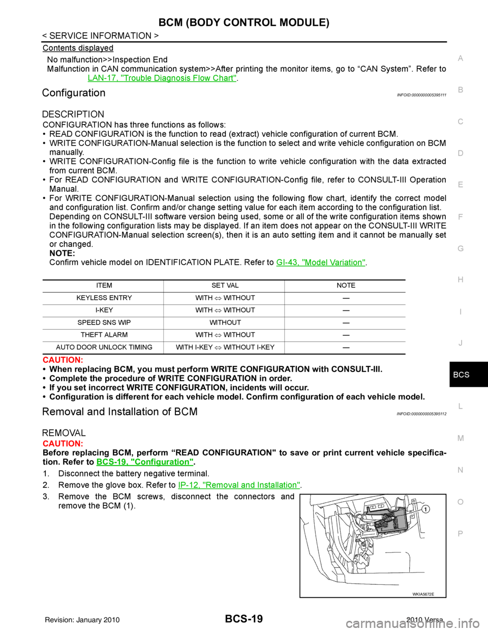
3. Remove the BCM screws, disconnect the connectors and remove the BCM (1).
ITEM SET VAL NOTE
KEYLESS ENTRY WITH ⇔ WITHOUT —
I-KEY WITH ⇔ WITHOUT —
SPEED SNS WIP WITHOUT —
THEFT ALARM WITH ⇔ WITHOUT —
AUTO DOOR UNLOCK TIMING WITH I-KEY ⇔ WITHOUT I-KEY —
WKIA5672E
Revision: January 20102010 Versa
Page 534 of 3745
POWER DOOR LOCK SYSTEMBL-25
< SERVICE INFORMATION >
C
DE
F
G H
J
K L
M A
B
BL
N
O P
AUTOMATIC DOOR LOCKS (UNLOCK OPERATION)
The automatic door locks (UNLOCK) function is the function that unlocks all doors linked with the key position.
IGN OFF Interlock Door Unlock*1
For vehicles equipped with Intelligent Key system, all doors are unlocked when the power supply position is
changed from ON to OFF.
For vehicles not equipped with Intelligent Key system , all doors are unlocked when the mechanical key is
removed from the ignition key cylinder.
BCM outputs the unlock signal to all door lock actuator s when it detects that the power supply position is
changed from ignition switch ON to OFF (with Intelligent Key) or when the mechanical key is removed from the
ignition key cylinder (without Intelligent Key).
Setting change of Automatic Door Locks (UNLOCK) Function
The lock operation setting of the aut omatic door locks function can be changed.
With CONSULT-III
The ON/OFF switching of the automatic door locks (UNL OCK) function and the type selection of the automatic
door locks (UNLOCK) function can be performed at the WORK SUPPORT setting of CONSULT-III. Refer to
BL-41, "
CONSULT-III Function (BCM)".
Without CONSULT- III
The automatic door locks (UNLOCK) function can be sw itched ON/OFF by performing the following operation.
1. Close all doors (door switch OFF).
2. Turn ignition switch ON.
3. Within 20 seconds of turning the ignition switch ON, press and hold the door lock and unlock switch to the UNLOCK position for more than 5 seconds.
4. The switching is completed when the hazard lamps blink.
5. The ignition switch must be turned OFF and ON again between each setting change.
*1: This function is set to ON before delivery.
CAN Communication System DescriptionINFOID:0000000005396555
Refer to LAN-7 .
OFF → ON : 2 blinks
ON → OFF : 1 blink
Revision: January 20102010 Versa
Page 569 of 3745
BL-60
< SERVICE INFORMATION >
REMOTE KEYLESS ENTRY SYSTEM
With CONSULT-III
Hazard reminder can be changed using “HAZARD LAMP SET” mode in “WORK SUPPORT”.
Horn reminder can be changed using “HORN CHIRP SET” mode in “WORK SUPPORT”.
Refer to BL-69, "
CONSULT-III Function (BCM)" .
Without CONSULT-III
Refer to Owner's Manual for instructions.
Auto Door Lock Operation
Auto lock function signal is sent for operation when any of the following signals are not sent within 1 minute
after the unlock signal is sent from the keyfob:
• when door switch is turned ON for open.
• when the key switch is turned ON.
• when the lock signal is sent from the keyfob.
Auto door lock mode can be changed using “AUT O LOCK SET” mode in “WORK SUPPORT”.
Refer to BL-69, "
CONSULT-III Function (BCM)" .
Panic Alarm Operation
When key switch is OFF (when ignition key is not inserted in key cylinder), BCM turns on and off horn intermit-
tently with input of PANIC ALARM signal from keyfob.
BCM outputs to IPDM E/R for panic alarm signal (horn signal) as DATA LINE (CAN H line and CAN L line).
The alarm automatically turns off after 25 seconds or when BCM receives any signal from keyfob.
Panic alarm operation mode can be changed using “P ANIC ALARM SET” mode in “WORK SUPPORT”.
Refer to BL-69, "
CONSULT-III Function (BCM)" .
Interior Lamp Operation
When the following conditions come:
• condition of interior lamp switch is in the DOOR position;
• door switch OFF (when all the doors are closed);
Remote keyless entry system turns on interior lamp (for 30 seconds) with input of UNLOCK signal from key-
fob. For detailed description, refer to LT- 9 4
.
CAN Communication System DescriptionINFOID:0000000005396575
Refer to LAN-7 .
Revision: January 20102010 Versa