2010 NISSAN LATIO air condition
[x] Cancel search: air conditionPage 2564 of 3745
![NISSAN LATIO 2010 Service Repair Manual CYLINDER BLOCKEM-205
< SERVICE INFORMATION > [MR18DE]
C
D
E
F
G H
I
J
K L
M A
EM
NP
O
How to Select Piston and BearingINFOID:0000000005398147
DESCRIPTION
• The identification grade stamped on each p NISSAN LATIO 2010 Service Repair Manual CYLINDER BLOCKEM-205
< SERVICE INFORMATION > [MR18DE]
C
D
E
F
G H
I
J
K L
M A
EM
NP
O
How to Select Piston and BearingINFOID:0000000005398147
DESCRIPTION
• The identification grade stamped on each p](/manual-img/5/57358/w960_57358-2563.png)
CYLINDER BLOCKEM-205
< SERVICE INFORMATION > [MR18DE]
C
D
E
F
G H
I
J
K L
M A
EM
NP
O
How to Select Piston and BearingINFOID:0000000005398147
DESCRIPTION
• The identification grade stamped on each part is the
grade for the dimension measured in new condition.
This grade cannot apply to reused parts.
• For reused or repaired parts, measure the dimens ion accurately. Determine the grade by comparing the
measurement with the values of each selection table.
• For details of the measurement method of each part , the reuse standards and the selection method of the
selective fitting parts, follow the applicable procedures.
HOW TO SELECT PISTON
When New Cylinder Block is Used
• Check the cylinder bore grade on rear left side of cylinder block (L), and select piston of the same grade.
• If there is a correction stamp mark on the cylinder block, use it as a correct reference.
When Cylinder Block is Reused
1. Measure the cylinder bore inner diameter. Refer to EM-212, "Inspection After Disassembly".
2. Determine the bore grade by comparing the measur ement with the values under the cylinder bore inner
diameter of the “Piston Selection Table”.
Selection points Selection parts Selection itemsSelection methods
Between cylinder block and
crankshaft Main bearing
Main bearing grade (bearing
thickness)Determined by match of cylin-
der block bearing housing
grade (inner diameter of hous-
ing) and crankshaft journal
grade (outer diameter of jour-
nal)
Between crankshaft and con-
necting rod Connecting rod bearing
Connecting rod bearing grade
(bearing thickness)Combining service grades for
connecting rod big end diame-
ter and crankshaft pin outer di-
ameter determine connecting
rod bearing selection.
Between cylinder block and pis-
ton Piston and piston pin assembly
(piston is available together with
piston pin as an assembly.) Piston grade (piston outer diam-
eter)
Piston grade = cylinder bore
grade (inner diameter of bore)
A : Correction stamp
B : Standard stamp
C : Cylinder No. 1 bore grade
D : Cylinder No. 2 bore grade
E : Cylinder No. 3 bore grade
F : Cylinder No. 4 bore grade
G : No. 1 main bearing housing grade
H : No. 2 main bearing housing grade
I : No. 3 main bearing housing grade
J : No. 4 main bearing housing grade
K : No. 5 main bearing housing grade
: Engine front
PBIC3264J
Revision: January 20102010 Versa
Page 2596 of 3745
![NISSAN LATIO 2010 Service Repair Manual EX-4
< PREPARATION >[HR16DE]
PREPARATION
PREPARATION
PREPARATION
Special Service ToolINFOID:0000000005399809
Commercial Service ToolINFOID:0000000005399810
Tool number
Tool nameDescription
KV10114400
NISSAN LATIO 2010 Service Repair Manual EX-4
< PREPARATION >[HR16DE]
PREPARATION
PREPARATION
PREPARATION
Special Service ToolINFOID:0000000005399809
Commercial Service ToolINFOID:0000000005399810
Tool number
Tool nameDescription
KV10114400](/manual-img/5/57358/w960_57358-2595.png)
EX-4
< PREPARATION >[HR16DE]
PREPARATION
PREPARATION
PREPARATION
Special Service ToolINFOID:0000000005399809
Commercial Service ToolINFOID:0000000005399810
Tool number
Tool nameDescription
KV10114400
(J-38365)
Heated oxygen sensor wrench Loosening or tightening heated oxygen sen-
sor
a: 22 mm (0.87 in)
NT636
(Kent-Moore No.)
Tool name
Description
(J-43897-18)
(J-43897-12)
Heated oxygen sensor thread cleaner Reconditioning the exhaust system threads
before installing new heated oxygen and Air
fuel ratio sensors (Use with anti-seize lubri-
cant shown below.)
a: 18 mm (0.71 in) dia. for zirconia heated
oxygen sensor
b: 12 mm (0.47 in) dia. for titania heated ox-
ygen sensor
Anti-seize lubricant (Permatex 133AR
or equivalent meeting MIL specifica-
tion MIL-A-907) Lubricating heated oxygen sensor thread
cleaner when reconditioning exhaust system
threads
Power tool Loosening bolts and nuts
AEM488
AEM489
PBIC0190E
Revision: January 20102010 Versa
Page 2602 of 3745
![NISSAN LATIO 2010 Service Repair Manual EX-10
< SERVICE INFORMATION >[MR18DE]
PREPARATION
PREPARATION
Special Service ToolINFOID:0000000005399816
Commercial Service ToolINFOID:0000000005399817
Tool number
Tool nameDescription
KV10114400
(J- NISSAN LATIO 2010 Service Repair Manual EX-10
< SERVICE INFORMATION >[MR18DE]
PREPARATION
PREPARATION
Special Service ToolINFOID:0000000005399816
Commercial Service ToolINFOID:0000000005399817
Tool number
Tool nameDescription
KV10114400
(J-](/manual-img/5/57358/w960_57358-2601.png)
EX-10
< SERVICE INFORMATION >[MR18DE]
PREPARATION
PREPARATION
Special Service ToolINFOID:0000000005399816
Commercial Service ToolINFOID:0000000005399817
Tool number
Tool nameDescription
KV10114400
(J-38365)
Heated oxygen sensor wrench Loosening or tightening heated oxygen sen-
sor
a: 22 mm (0.87 in)
NT636
(Kent-Moore No.)
Tool name
Description
(J-43897-18)
(J-43897-12)
Heated oxygen sensor thread cleaner Reconditioning the exhaust system threads
before installing new heated oxygen and Air
fuel ratio sensors (Use with anti-seize lubri-
cant shown below.)
a: 18 mm (0.71 in) dia. for zirconia heated
oxygen sensor
b: 12 mm (0.47 in) dia. for titania heated ox-
ygen sensor
Anti-seize lubricant (Permatex 133AR
or equivalent meeting MIL specifica-
tion MIL-A-907) Lubricating heated oxygen sensor thread
cleaner when reconditioning exhaust system
threads
Power tool Loosening bolts and nuts
AEM488
AEM489
PBIC0190E
Revision: January 20102010 Versa
Page 2650 of 3745

PRECAUTIONSFSU-3
< SERVICE INFORMATION >
C
DF
G H
I
J
K L
M A
B
FSU
N
O P
5. When the repair work is completed, return the ignition switch to the ″LOCK ″ position before connecting
the battery cables. (At this time, the steering lock mechanism will engage.)
6. Perform a self-diagnosis check of al l control units using CONSULT-III.
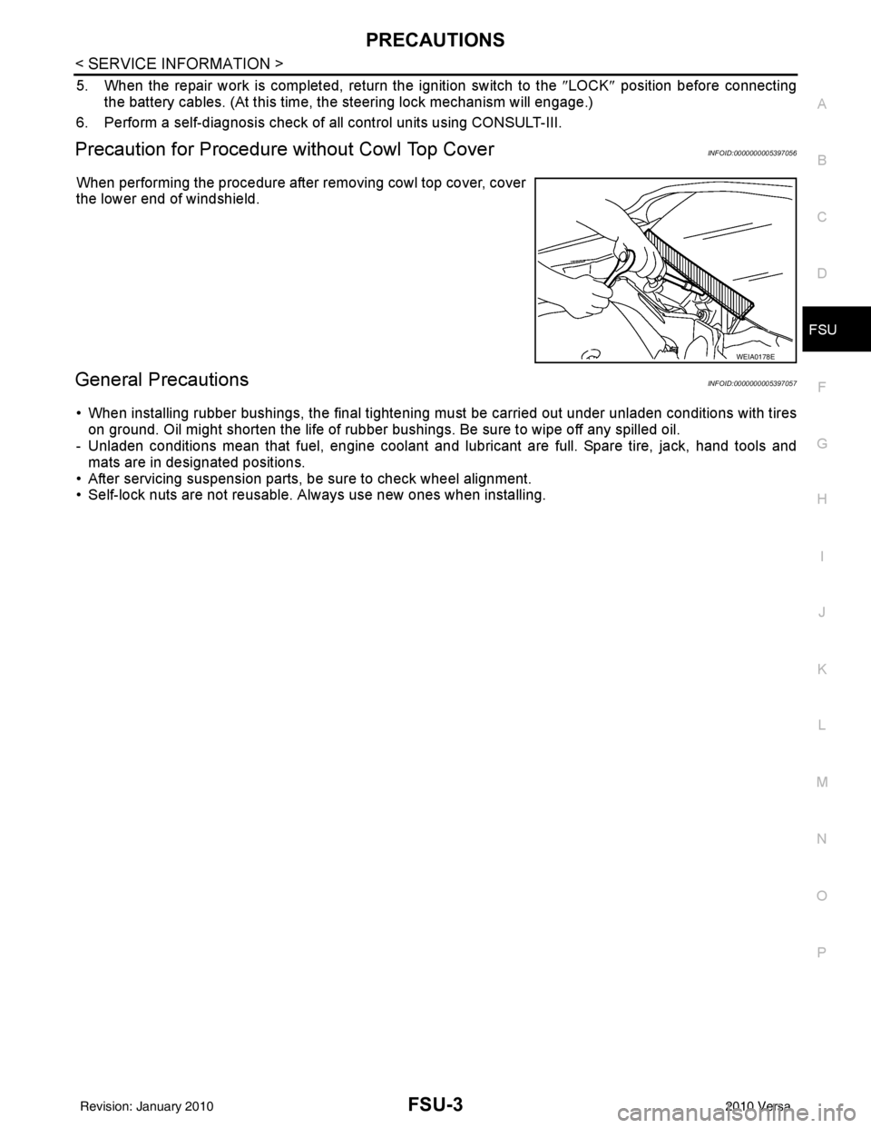
Precaution for Procedure without Cowl Top CoverINFOID:0000000005397056
When performing the procedure after removing cowl top cover, cover
the lower end of windshield.
General PrecautionsINFOID:0000000005397057
• When installing rubber bushings, the final tightening mu st be carried out under unladen conditions with tires
on ground. Oil might shorten the life of rubber bushings. Be sure to wipe off any spilled oil.
- Unladen conditions mean that fuel, engine coolant and l ubricant are full. Spare tire, jack, hand tools and
mats are in designated positions.
• After servicing suspension parts, be sure to check wheel alignment.
• Self-lock nuts are not reusable. A lways use new ones when installing.
WEIA0178E
Revision: January 20102010 Versa
Page 2654 of 3745

FRONT SUSPENSION ASSEMBLYFSU-7
< SERVICE INFORMATION >
C
DF
G H
I
J
K L
M A
B
FSU
N
O P
FRONT SUSPENSION ASSEMBLY
On-Vehicle Inspection and ServiceINFOID:0000000005397061
Make sure the mounting conditions (looseness, back lash) of each component and component conditions
(wear, damage) are normal.
INSPECTION OF LOWER BALL JOINT END PLAY
1. Set front wheels in a straight-ahead position. Do not depress brake pedal.
2. Place an iron bar or similar tool between transverse link and steering knuckle.
3. Measure axial end play by prying it up and down.
CAUTION:
Be careful not to damage ball joint boot. Do not damage the installation position by applying
excessive force.
STRUT INSPECTION
Check for oil leakage, damage and replace as necessary.
Wheel Alignment InspectionINFOID:0000000005397062
PRELIMINARY INSPECTION
WARNING:
Always adjust the alignment with the vehicle on a flat surface.
NOTE:
If alignment is out of specification, inspect and replace any damaged or worn rear suspension parts before
making any adjustments.
1. Check and adjust the wheel alignment with the vehicle under unladen conditions. “Unladen conditions”
means that the fuel, coolant, and lubricant are full; and that the spare tire, jack, hand tools and mats are in
their designated positions.
2. Check the tires for incorrect air pressure and excessive wear.
3. Check the wheels for run out and damage. Refer to WT-6, "
Inspection" .
4. Check the wheel bearing axial end play. Refer to FAX-6, "
On-Vehicle Inspection and Service" .
5. Check the shock absorbers for leaks or damage.
6. Check each mounting point of the suspension components for any excessive looseness or damage.
7. Check each link, arm, and the suspension member for any damage.
8. Check the vehicle height. Refer to FSU-19, "
Wheelarch Height (Unladen*)" .
GENERAL INFORMATION AND RECOMMENDATIONS
1. A Four-Wheel Thrust Alignment should be performed.
• This type of alignment is re commended for any NISSAN vehicle.
• The four-wheel “thrust” process helps ensure that the vehicle is properly aligned and the steering wheel
is centered.
• The alignment machine itself should be ca pable of accepting any NISSAN vehicle.
• The alignment machine should be checked to ensure that it is level.
2. Make sure the alignment machine is properly calibrated. • Your alignment machine should be regularly calibrated in order to give correct information.
• Check with the manufacturer of your specific a lignment machine for their recommended Service/Cali-
bration Schedule.
THE ALIGNMENT PROCESS
IMPORTANT: Use only the alignment specifications listed in this Service Manual. Refer to FSU-17, "Wheel
Alignment (Unladen*)" .
1. When displaying the alignment settings, many alignm ent machines use “indicators”: (Green/red, plus or
minus, Go/No Go). Do NOT use these indicators.
• The alignment specifications programmed into your alignment machine that operate these indicators may not be correct.Axial end play : 0 mm (0 in)
Revision: January 20102010 Versa
Page 2667 of 3745

GI-1
GENERAL INFORMATION
C
DE
F
G H
I
J
K L
M B
GI
SECTION GI
N
O P
CONTENTS
GENERAL INFORMATION
SERVICE INFORMATION .. ..........................2
PRECAUTIONS .............................................. .....2
Description .......................................................... ......2
Precaution for Supplemental Restraint System
(SRS) "AIR BAG" and "SEAT BELT PRE-TEN-
SIONER" ...................................................................
2
Precaution Necessary for Steering Wheel Rota-
tion After Battery Disconnect ............................... ......
2
General Precaution ...................................................3
Precaution for Three Way Catalyst ...........................4
Precaution for Fuel (Unleaded Regular Gasoline
Recommended) .........................................................
4
Precaution for Multiport Fuel Injection System or
Engine Control System .............................................
5
Precaution for Hoses .................................................5
Precaution for Engine Oils ........................................6
Precaution for Air Conditioning .................................6
HOW TO USE THIS MANUAL ............................7
Description .......................................................... ......7
Terms ........................................................................7
Units ..........................................................................7
Contents ....................................................................7
Relation between Illustrations and Descriptions .......8
Component ................................................................8
How to Follow Trouble Diagnosis ..............................9
How to Read Wiring Diagram ..................................13
Abbreviations ...................................................... ....20
SERVICE INFORMATION FOR ELECTRICAL
INCIDENT ...........................................................
22
How to Check Terminal ...........................................22
How to Perform Efficient Diagnosis for an Electri-
cal Incident .......................................................... ....
25
Control Units and Electrical Parts ............................32
CONSULT-III CHECKING SYSTEM .................35
Description ...............................................................35
Function and System Application ............................35
CONSULT-III Data Link Connector (DLC) Circuit ....36
LIFTING POINT .................................................38
Special Service Tool ................................................38
Garage Jack and Safety Stand and 2-Pole Lift .......38
Board-On Lift ...........................................................39
TOW TRUCK TOWING .....................................40
Tow Truck Towing ...................................................40
Vehicle Recovery (Freeing a Stuck Vehicle) ...........40
TIGHTENING TORQUE OF STANDARD
BOLTS ...............................................................
41
Tightening Torque Table .........................................41
RECOMMENDED CHEMICAL PRODUCTS
AND SEALANTS ...............................................
42
Recommended Chemical Product and Sealant .......42
IDENTIFICATION INFORMATION ....................43
Model Variation ........................................................43
Dimensions ..............................................................46
Wheels & Tires ........................................................46
TERMINOLOGY ................................................48
SAE J1930 Terminology List ...................................48
Revision: January 20102010 Versa
Page 2672 of 3745

GI-6
< SERVICE INFORMATION >
PRECAUTIONS
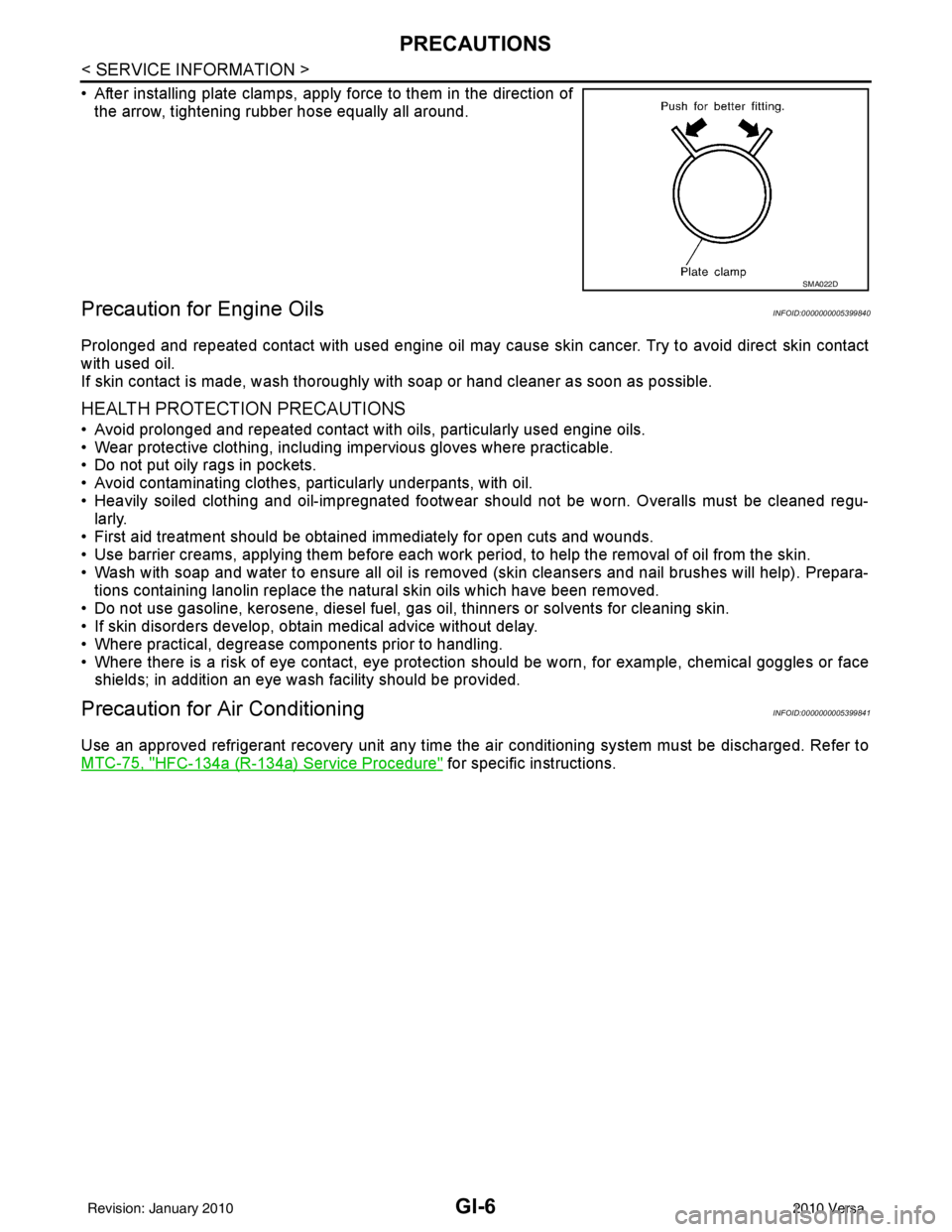
• After installing plate clamps, apply force to them in the direction ofthe arrow, tightening rubber hose equally all around.
Precaution for Engine OilsINFOID:0000000005399840
Prolonged and repeated contact with used engine oil may cause skin cancer. Try to avoid direct skin contact
with used oil.
If skin contact is made, wash thoroughly with soap or hand cleaner as soon as possible.
HEALTH PROTECTION PRECAUTIONS
• Avoid prolonged and repeated contact with oils, particularly used engine oils.
• Wear protective clothing, including impervious gloves where practicable.
• Do not put oily rags in pockets.
• Avoid contaminating clothes, pa rticularly underpants, with oil.
• Heavily soiled clothing and oil-impregnated footwear should not be worn. Overalls must be cleaned regu- larly.
• First aid treatment should be obtained immediately for open cuts and wounds.
• Use barrier creams, applying them before each work period, to help the removal of oil from the skin.
• Wash with soap and water to ensure all oil is removed (skin cleansers and nail brushes will help). Prepara-
tions containing lanolin replace the natural skin oils which have been removed.
• Do not use gasoline, kerosene, diesel fuel, gas oil, thinners or solvents for cleaning skin.
• If skin disorders develop, obtain medical advice without delay.
• Where practical, degrease components prior to handling.
• Where there is a risk of eye contact, eye protection should be worn, for example, chemical goggles or face
shields; in addition an eye wash facility should be provided.
Precaution for Air ConditioningINFOID:0000000005399841
Use an approved refrigerant recovery unit any time t he air conditioning system must be discharged. Refer to
MTC-75, "
HFC-134a (R-134a) Service Procedure" for specific instructions.
SMA022D
Revision: January 20102010 Versa
Page 2686 of 3745

GI-20
< SERVICE INFORMATION >
HOW TO USE THIS MANUAL
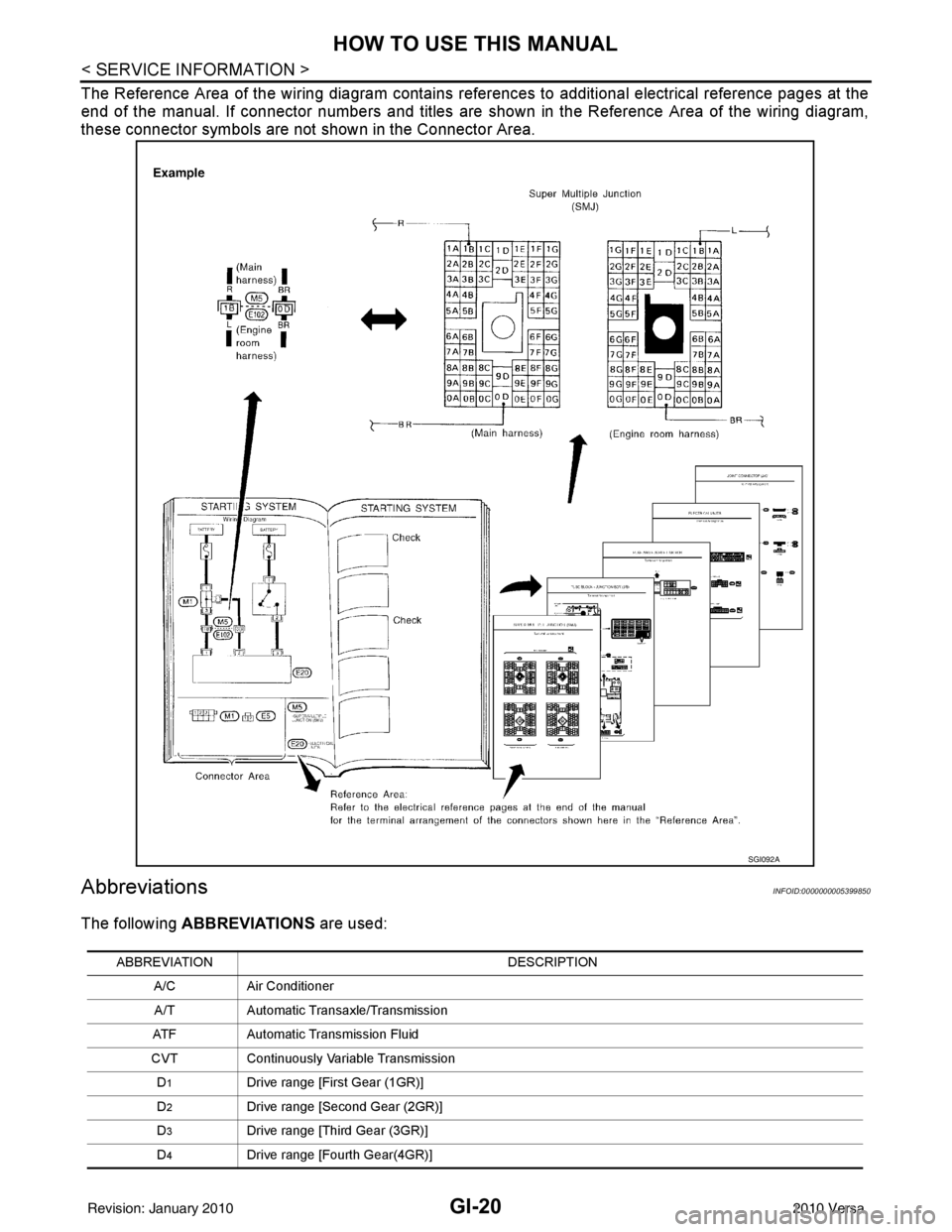
The Reference Area of the wiring diagram contains references to additional electrical reference pages at the
end of the manual. If connector numbers and titles are shown in the Reference Area of the wiring diagram,
these connector symbols are not shown in the Connector Area.
AbbreviationsINFOID:0000000005399850
The following ABBREVIATIONS are used:
SGI092A
ABBREVIATION DESCRIPTION
A/C Air Conditioner
A/T Automatic Transaxle/Transmission
ATF Automatic Transmission Fluid
CVT Continuously Variable Transmission
D
1Drive range [First Gear (1GR)]
D
2Drive range [Second Gear (2GR)]
D
3Drive range [Third Gear (3GR)]
D
4Drive range [Fourth Gear(4GR)]
Revision: January 20102010 Versa