2010 NISSAN LATIO air condition
[x] Cancel search: air conditionPage 3674 of 3745
![NISSAN LATIO 2010 Service Repair Manual STC-28
< SYMPTOM DIAGNOSIS >[EPS]
UNBALANCE STEERING WHEEL TURNING FORCE AND RETURN BETWEEN
RIGHT AND LEFT
UNBALANCE STEERING WHEEL TU RNING FORCE AND RETURN BE-
TWEEN RIGHT AND LEFT
DescriptionINFOI NISSAN LATIO 2010 Service Repair Manual STC-28
< SYMPTOM DIAGNOSIS >[EPS]
UNBALANCE STEERING WHEEL TURNING FORCE AND RETURN BETWEEN
RIGHT AND LEFT
UNBALANCE STEERING WHEEL TU RNING FORCE AND RETURN BE-
TWEEN RIGHT AND LEFT
DescriptionINFOI](/manual-img/5/57358/w960_57358-3673.png)
STC-28
< SYMPTOM DIAGNOSIS >[EPS]
UNBALANCE STEERING WHEEL TURNING FORCE AND RETURN BETWEEN
RIGHT AND LEFT
UNBALANCE STEERING WHEEL TU RNING FORCE AND RETURN BE-
TWEEN RIGHT AND LEFT
DescriptionINFOID:0000000005600201
Unbalance steering wheel turning force and return between right and left.
Diagnosis ProcedureINFOID:0000000005600202
1.CHECK THE ILLUMINATION OF THE EPS WARNING LAMP
Check that the EPS warning lamp turns ON when igni tion switch turns ON. Then, EPS warning lamp turns
OFF after the engine is started.
Is the inspection result normal?
YES >> GO TO 2.
NO >> Refer to STC-26, "
Diagnosis Procedure".
2.CHECK WHEEL ALIGNMENT
1. Check the wheel alignment. Refer to FSU-7, "
On-Vehicle Inspection and Service".
2. Perform EPS control unit self-diagnosis.
Is the inspection result normal?
YES >> GO TO 3.
NO >> Adjustment of wheel alignment.
3.CHECK EPS CONTROL UNIT SIGNAL
With CONSULT-III
1. Start the engine. CAUTION:
Stop the vehicle.
2. Turn steering wheel from full left stop to full right stop.
3. Select “TORQUE SENSOR” of “DATA MONITOR” for EPS control unit.
Is the inspection result normal?
YES >> GO TO 5.
NO >> GO TO 4.
4.CHECK EPS MOTOR
Perform the trouble diagnosis of EPS motor. Refer to STC-13, "
Diagnosis Procedure".
Is the inspection result normal?
YES >> GO TO 5.
NO >> Repair or replace the specific malfunctioning part.
5.CHECK STEERING WHEEL TURNING FORCE
Check the steering wheel turning force. Refer to PS-6, "
On-Vehicle Inspection and Service".
Is the inspection result normal?
YES >> Inspection End.
NO >> Check the steering wheel turning force for mechanical malfunction. Refer to PS-6, "
On-Vehicle
Inspection and Service".
Monitor item ConditionDisplay value
TORQUE SENSOR Steering wheel: Not steer-
ing (There is no steering
force)
Approx. 0 Nm
Steering wheel: Right turn Positive value (Nm)
Steering wheel: Left turn Negative value (Nm)
Revision: January 20102010 Versa
Page 3675 of 3745
![NISSAN LATIO 2010 Service Repair Manual UNBALANCE STEERING WHEEL TURNING FORCE (TORQUE VARIATION)
STC-29
< SYMPTOM DIAGNOSIS > [EPS]
C
D
E
F
H I
J
K L
M A
B
STC
N
O P
UNBALANCE STEERING WHEEL TU RNING FORCE (TORQUE VARIA-
TION)
DescriptionI NISSAN LATIO 2010 Service Repair Manual UNBALANCE STEERING WHEEL TURNING FORCE (TORQUE VARIATION)
STC-29
< SYMPTOM DIAGNOSIS > [EPS]
C
D
E
F
H I
J
K L
M A
B
STC
N
O P
UNBALANCE STEERING WHEEL TU RNING FORCE (TORQUE VARIA-
TION)
DescriptionI](/manual-img/5/57358/w960_57358-3674.png)
UNBALANCE STEERING WHEEL TURNING FORCE (TORQUE VARIATION)
STC-29
< SYMPTOM DIAGNOSIS > [EPS]
C
D
E
F
H I
J
K L
M A
B
STC
N
O P
UNBALANCE STEERING WHEEL TU RNING FORCE (TORQUE VARIA-
TION)
DescriptionINFOID:0000000005600203
Unbalance steering wheel turning force (torque variation).
Diagnosis ProcedureINFOID:0000000005600204
1.CHECK THE ILLUMINATION OF THE EPS WARNING LAMP
Check that the EPS warning lamp turns ON when igni tion switch turns ON. Then, EPS warning lamp turns
OFF after the engine is started.
Is the inspection result normal?
YES >> GO TO 2.
NO >> Refer to STC-26, "
Diagnosis Procedure".
2.CHECK STEERING COLU MN AND STEERING GEAR
Check the steering column assembly and steering gear assembly.
• Steering column assembly. Refer to PS-9, "
Removal and Installation".
• Steering gear assembly. Refer to PS-12, "
Disassembly and Assembly".
Is the inspection result normal?
YES >> GO TO 3.
NO >> Repair or replace the specific malfunctioning part.
3.CHECK EPS CONTROL UNIT SIGNAL
With CONSULT-III
1. Start the engine. CAUTION:
Stop the vehicle.
2. Turn steering wheel from full left stop to full right stop.
3. Select “TORQUE SENSOR” of “DATA MONITOR” for EPS control unit.
Is the inspection result normal?
YES >> GO TO 5.
NO >> GO TO 4.
4.CHECK EPS MOTOR
Perform the trouble diagnosis of EPS motor. Refer to STC-13, "
Diagnosis Procedure".
Is the inspection result normal?
YES >> GO TO 5.
NO >> Repair or replace the specific malfunctioning part.
5.CHECK STEERING WH EEL TURNING FORCE
Check the steering wheel turning force. Refer to PS-6, "
On-Vehicle Inspection and Service".
Is the inspection result normal?
YES >> Inspection End.
NO >> Check the steering wheel turning force for mechanical malfunction. Refer to PS-6, "
On-Vehicle
Inspection and Service".
Monitor item ConditionDisplay value
TORQUE SENSOR Steering wheel: Not steer-
ing (There is no steering
force)
Approx. 0 Nm
Steering wheel: Right turn Positive value (Nm)
Steering wheel: Left turn Negative value (Nm)
Revision: January 20102010 Versa
Page 3677 of 3745
![NISSAN LATIO 2010 Service Repair Manual PRECAUTIONSSTC-31
< PRECAUTION > [EPS]
C
D
E
F
H I
J
K L
M A
B
STC
N
O P
5. When the repair work is completed, return the ignition switch to the ″LOCK ″ position before connecting
the battery cab NISSAN LATIO 2010 Service Repair Manual PRECAUTIONSSTC-31
< PRECAUTION > [EPS]
C
D
E
F
H I
J
K L
M A
B
STC
N
O P
5. When the repair work is completed, return the ignition switch to the ″LOCK ″ position before connecting
the battery cab](/manual-img/5/57358/w960_57358-3676.png)
PRECAUTIONSSTC-31
< PRECAUTION > [EPS]
C
D
E
F
H I
J
K L
M A
B
STC
N
O P
5. When the repair work is completed, return the ignition switch to the ″LOCK ″ position before connecting
the battery cables. (At this time, the steering lock mechanism will engage.)
6. Perform a self-diagnosis check of al l control units using CONSULT-III.
Service Notice or Precaution for EPS SystemINFOID:0000000005602354
CAUTION:
Check or confirm the following item wh en performing the trouble diagnosis.
• Check any possible causes by interviewing the symptom and it’s condition from the customer if any
malfunction, such as EPS warn ing lamp turns ON, occurs.
• Check if air pressure and size of tires are proper, the specified part is used for the steering wheel,
and control unit is genuine part.
• Check if the connection of steer ing column assembly and steering gear assembly is proper (there is
not looseness of mounting bolts, damage of rods, boots or sealants, and leakage of grease, etc).
• Check if the wheel alignment is adjusted properly.
• Check if there is any damage or modification to su spension or body resulting in increased weight or
altered ground clearance.
• Check if installation conditions of each link and suspension are proper.
• Check if the battery voltage is proper
• Check connection conditions of each connector are proper.
• Before connecting or disconnect ing the EPS control unit har-
ness connector, turn ignition switch “OFF” and disconnect
battery ground cable. Because battery voltage is applied to
EPS control unit even if igniti on switch is turned “OFF”.
• When connecting or disconnect ing pin connectors into or
from EPS control unit, take care not to damage pin terminals
(bend or break).
When connecting pin connectors, make sure that there are no
bends or breaks on EPS control unit pin terminal.
• Before replacing EPS control unit, perform EPS control unit input/output signal inspectio n and make sure whether EPS
control unit functions properly or not. Refer to STC-20, "
Ref-
erence Value".
SEF289H
SEF291H
SDIA1848E
Revision: January 20102010 Versa
Page 3686 of 3745
TIRE PRESSURE MONITORING SYSTEMWT-9
< SERVICE INFORMATION >
C
DF
G H
I
J
K L
M A
B
WT
N
O P
TIRE PRESSURE MO NITORING SYSTEM
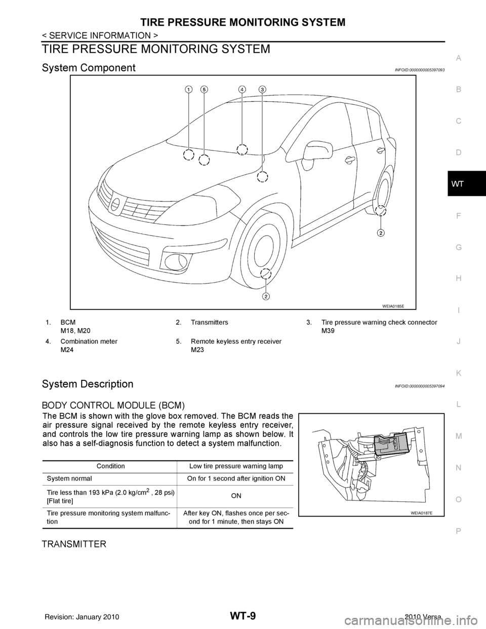
System ComponentINFOID:0000000005397093
System DescriptionINFOID:0000000005397094
BODY CONTROL MODULE (BCM)
The BCM is shown with the glove box removed. The BCM reads the
air pressure signal received by the remote keyless entry receiver,
and controls the low tire pressure warning lamp as shown below. It
also has a self-diagnosis function to detect a system malfunction.
TRANSMITTER
WEIA0185E
1. BCM
M18, M20 2. Transmitters 3. Tire pressure warning check connector
M39
4. Combination meter M24 5. Remote keyless entry receiver
M23
Condition Low tire pressure warning lamp
System normal On for 1 second after ignition ON
Tire less than 193 kPa (2.0 kg/cm
2 , 28 psi)
[Flat tire] ON
Tire pressure monitoring system malfunc-
tion After key ON, flashes once per sec-
ond for 1 minute, then stays ON
WEIA0187E
Revision: January 20102010 Versa
Page 3687 of 3745
WT-10
< SERVICE INFORMATION >
TIRE PRESSURE MONITORING SYSTEM
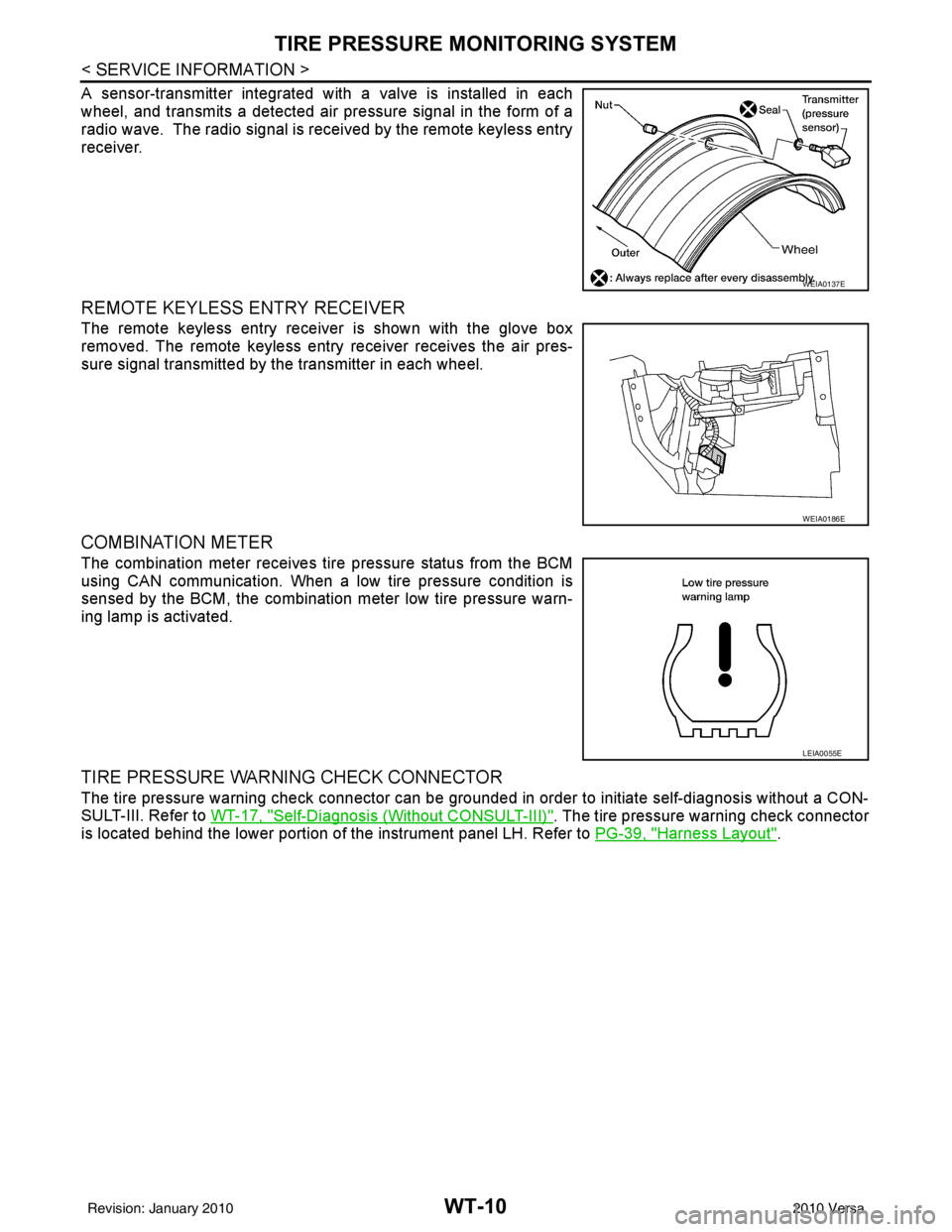
A sensor-transmitter integrated with a valve is installed in each
wheel, and transmits a detected air pressure signal in the form of a
radio wave. The radio signal is received by the remote keyless entry
receiver.
REMOTE KEYLESS ENTRY RECEIVER
The remote keyless entry receiver is shown with the glove box
removed. The remote keyless entry receiver receives the air pres-
sure signal transmitted by the transmitter in each wheel.
COMBINATION METER
The combination meter receives tire pressure status from the BCM
using CAN communication. When a low tire pressure condition is
sensed by the BCM, the combination meter low tire pressure warn-
ing lamp is activated.
TIRE PRESSURE WARNING CHECK CONNECTOR
The tire pressure warning check connector can be grounded in order to initiate self-diagnosis without a CON-
SULT-III. Refer to WT-17, "
Self-Diagnosis (Without CONSULT-III)". The tire pressure warning check connector
is located behind the lower portion of the instrument panel LH. Refer to PG-39, "
Harness Layout".
WEIA0137E
WEIA0186E
LEIA0055E
Revision: January 20102010 Versa
Page 3694 of 3745
TROUBLE DIAGNOSESWT-17
< SERVICE INFORMATION >
C
DF
G H
I
J
K L
M A
B
WT
N
O P
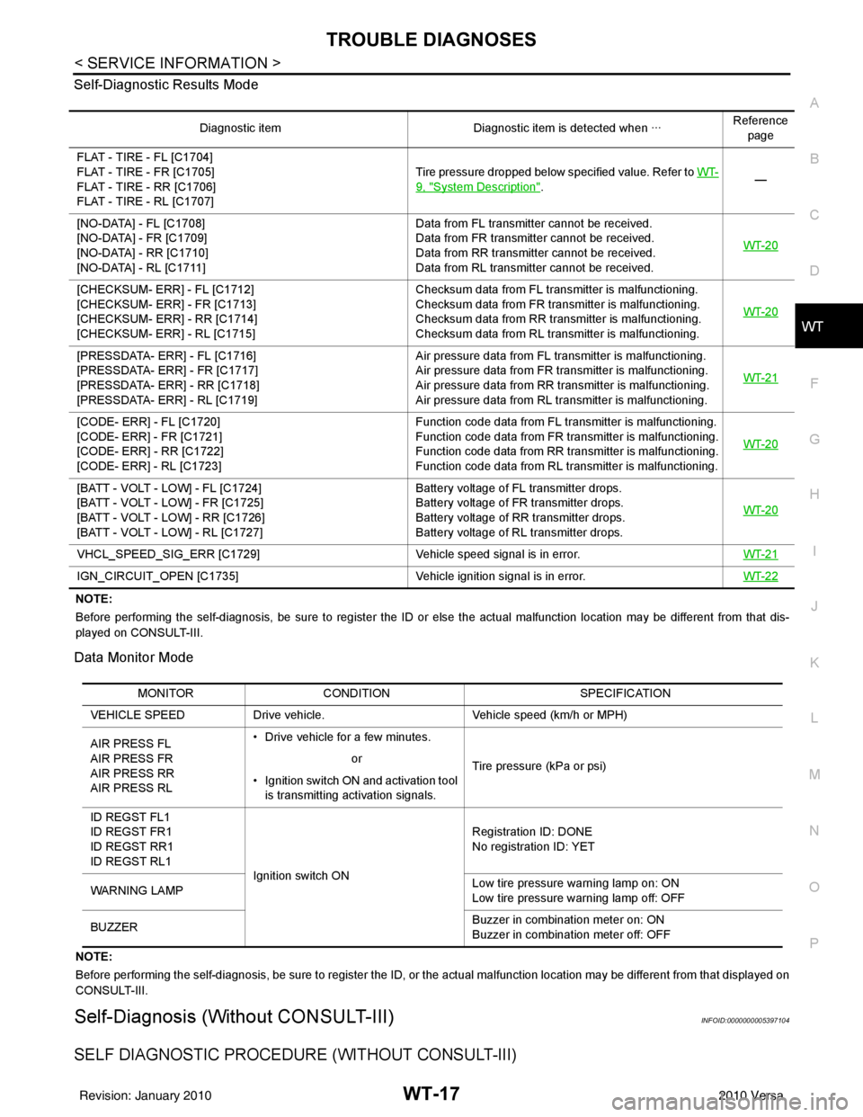
Self-Diagnostic Results Mode
NOTE:
Before performing the self-diagnosis, be sure to register the ID or else the actual malfunction location may be different from
that dis-
played on CONSULT-III.
Data Monitor Mode
NOTE:
Before performing the self-diagnosis, be sure to register the ID, or the actual malfunction location may be different from that displayed on
CONSULT-III.
Self-Diagnosis (Without CONSULT-III)INFOID:0000000005397104
SELF DIAGNOSTIC PROCE DURE (WITHOUT CONSULT-III)
Diagnostic item Diagnostic item is detected when ···Reference
page
FLAT - TIRE - FL [C1704]
FLAT - TIRE - FR [C1705]
FLAT - TIRE - RR [C1706]
FLAT - TIRE - RL [C1707] Tire pressure dropped below specified value. Refer to WT-
9, "System Description".
—
[NO-DATA] - FL [C1708]
[NO-DATA] - FR [C1709]
[NO-DATA] - RR [C1710]
[NO-DATA] - RL [C1711] Data from FL transmitter cannot be received.
Data from FR transmitter cannot be received.
Data from RR transmitter cannot be received.
Data from RL transmitter cannot be received.
WT-20
[CHECKSUM- ERR] - FL [C1712]
[CHECKSUM- ERR] - FR [C1713]
[CHECKSUM- ERR] - RR [C1714]
[CHECKSUM- ERR] - RL [C1715] Checksum data from FL transmitter is malfunctioning.
Checksum data from FR transmitter is malfunctioning.
Checksum data from RR transmitter is malfunctioning.
Checksum data from RL transmitter is malfunctioning.
WT-20
[PRESSDATA- ERR] - FL [C1716]
[PRESSDATA- ERR] - FR [C1717]
[PRESSDATA- ERR] - RR [C1718]
[PRESSDATA- ERR] - RL [C1719] Air pressure data from FL transmitter is malfunctioning.
Air pressure data from FR transmitter is malfunctioning.
Air pressure data from RR transmitter is malfunctioning.
Air pressure data from RL transmitter is malfunctioning.
WT-21
[CODE- ERR] - FL [C1720]
[CODE- ERR] - FR [C1721]
[CODE- ERR] - RR [C1722]
[CODE- ERR] - RL [C1723] Function code data from FL transmitter is malfunctioning.
Function code data from FR transmitter is malfunctioning.
Function code data from RR transmitter is malfunctioning.
Function code data from RL transmitter is malfunctioning.
WT-20
[BATT - VOLT - LOW] - FL [C1724]
[BATT - VOLT - LOW] - FR [C1725]
[BATT - VOLT - LOW] - RR [C1726]
[BATT - VOLT - LOW] - RL [C1727] Battery voltage of FL transmitter drops.
Battery voltage of FR transmitter drops.
Battery voltage of RR transmitter drops.
Battery voltage of RL transmitter drops.
WT-20
VHCL_SPEED_SIG_ERR [C1729]
Vehicle speed signal is in error. WT-21
IGN_CIRCUIT_OPEN [C1735] Vehicle ignition signal is in error. WT-22
MONITORCONDITION SPECIFICATION
VEHICLE SPEED Drive vehicle. Vehicle speed (km/h or MPH)
AIR PRESS FL
AIR PRESS FR
AIR PRESS RR
AIR PRESS RL • Drive vehicle for a few minutes.
Tire pressure (kPa or psi)
or
• Ignition switch ON and activation tool is transmitting activation signals.
ID REGST FL1
ID REGST FR1
ID REGST RR1
ID REGST RL1 Ignition switch ON Registration ID: DONE
No registration ID: YET
WARNING LAMP Low tire pressure
warning lamp on: ON
Low tire pressure warning lamp off: OFF
BUZZER Buzzer in combination meter on: ON
Buzzer in combination meter off: OFF
Revision: January 20102010 Versa
Page 3720 of 3745
FRONT WIPER AND WASHER SYSTEMWW-15
< SERVICE INFORMATION >
C
DE
F
G H
I
J
L
M A
B
WW
N
O P
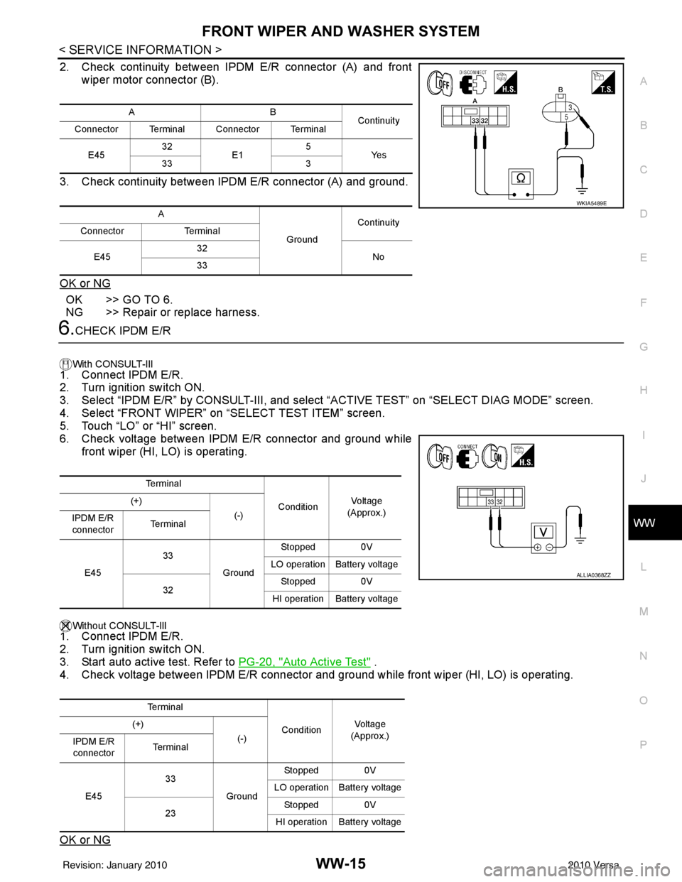
2. Check continuity between IPDM E/R connector (A) and front wiper motor connector (B).
3. Check continuity between IPDM E/R connector (A) and ground.
OK or NG
OK >> GO TO 6.
NG >> Repair or replace harness.
6.CHECK IPDM E/R
With CONSULT-lIl
1. Connect IPDM E/R.
2. Turn ignition switch ON.
3. Select “IPDM E/R” by CONSULT-III, and sele ct “ACTIVE TEST” on “SELECT DIAG MODE” screen.
4. Select “FRONT WIPER” on “SELECT TEST ITEM” screen.
5. Touch “LO” or “HI” screen.
6. Check voltage between IPDM E/R connector and ground while
front wiper (HI, LO) is operating.
Without CONSULT-llI1. Connect IPDM E/R.
2. Turn ignition switch ON.
3. Start auto active test. Refer to PG-20, "
Auto Active Test" .
4. Check voltage between IPDM E/R connector and gr ound while front wiper (HI, LO) is operating.
OK or NG
AB Continuity
Connector Terminal Connector Terminal
E45 32
E1 5
Ye s
33 3
A GroundContinuity
Connector Terminal
E45 32
No
33
WKIA5489E
Te r m i n a l
ConditionVo l ta g e
(Approx.)
(+)
(-)
IPDM E/R
connector Te r m i n a l
E45 33
GroundStopped 0V
LO operation Battery voltage
32 Stopped 0V
HI operation Battery voltage
Te r m i n a l ConditionVol tag e
(Approx.)
(+)
(-)
IPDM E/R
connector Te r m i n a l
E45 33
GroundStopped 0V
LO operation Battery voltage
23 Stopped 0V
HI operation Battery voltage
ALLIA0368ZZ
Revision: January 20102010 Versa
Page 3736 of 3745
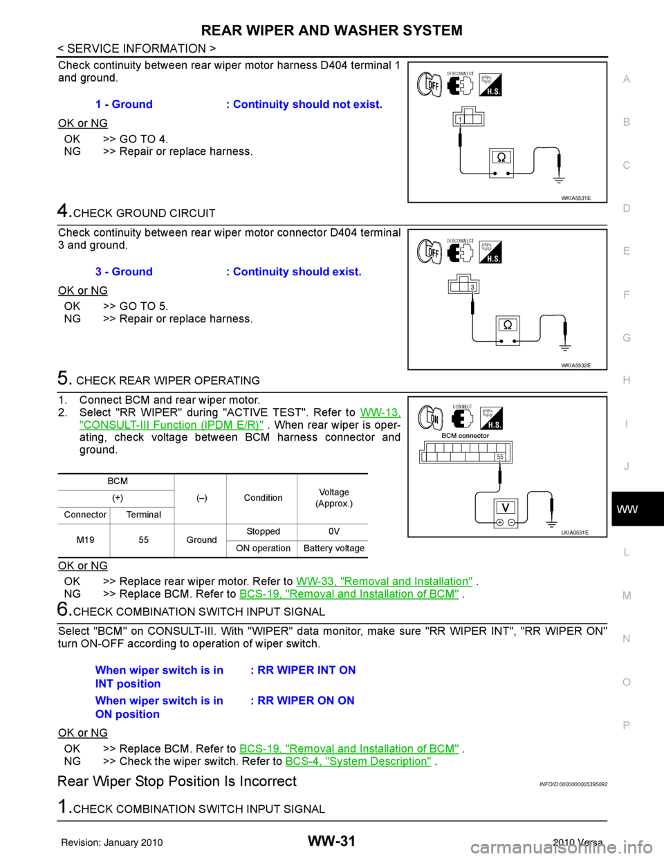
REAR WIPER AND WASHER SYSTEMWW-31
< SERVICE INFORMATION >
C
DE
F
G H
I
J
L
M A
B
WW
N
O P
Check continuity between rear wiper motor harness D404 terminal 1
and ground.
OK or NG
OK >> GO TO 4.
NG >> Repair or replace harness.
4.CHECK GROUND CIRCUIT
Check continuity between rear wiper motor connector D404 terminal
3 and ground.
OK or NG
OK >> GO TO 5.
NG >> Repair or replace harness.
5. CHECK REAR WIPER OPERATING
1. Connect BCM and rear wiper motor.
2. Select "RR WIPER" during "ACTIVE TEST". Refer to WW-13,
"CONSULT-III Function (IPDM E/R)" . When rear wiper is oper-
ating, check voltage between BCM harness connector and
ground.
OK or NG
OK >> Replace rear wiper motor. Refer to WW-33, "Removal and Installation" .
NG >> Replace BCM. Refer to BCS-19, "
Removal and Installation of BCM" .
6.CHECK COMBINATION SWITCH INPUT SIGNAL
Select "BCM" on CONSULT-III. With "WIPER" data monitor, make sure "RR WIPER INT", "RR WIPER ON"
turn ON-OFF according to operation of wiper switch.
OK or NG
OK >> Replace BCM. Refer to BCS-19, "Removal and Installation of BCM" .
NG >> Check the wiper switch. Refer to BCS-4, "
System Description" .
Rear Wiper Stop Posi tion Is IncorrectINFOID:0000000005395092
1.CHECK COMBINATION SWITCH INPUT SIGNAL1 - Ground : Continuity should not exist.
WKIA5531E
3 - Ground
: Continuity should exist.
WKIA5532E
BCM
(–) Condition Vo l ta g e
(Approx.)
(+)
Connector Terminal
M19 55 Ground Stopped
0V
ON operation Battery voltage
LKIA0551E
When wiper switch is in
INT position : RR WIPER INT ON
When wiper switch is in
ON position : RR WIPER ON ON
Revision: January 20102010 Versa