2010 NISSAN LATIO air condition
[x] Cancel search: air conditionPage 3572 of 3745

SE-6
< SERVICE INFORMATION >
SQUEAK AND RATTLE TROUBLE DIAGNOSES
If the noise can be duplicated easily during the test drive, to help identify the source of the noise, try to dupli-
cate the noise with the vehicle stopped by doing one or all of the following:
1) Close a door.
2) Tap or push/pull around the area where the noise appears to be coming from.
3) Rev the engine.
4) Use a floor jack to recreate vehicle “twist”.
5) At idle, apply engine load (electrical load, half-clutch on M/T model, drive position on A/T model).
6) Raise the vehicle on a hoist and hit a tire with a rubber hammer.
• Drive the vehicle and attempt to duplicate the conditions the customer states exist when the noise occurs.
• If it is difficult to duplicate the noise, drive the v ehicle slowly on an undulating or rough road to stress the
vehicle body.
CHECK RELATED SERVICE BULLETINS
After verifying the customer concern or symptom, chec k ASIST for Technical Service Bulletins (TSBs) related
to that concern or symptom.
If a TSB relates to the symptom, follo w the procedure to repair the noise.
LOCATE THE NOISE AND IDENTIFY THE ROOT CAUSE
1. Narrow down the noise to a general area.To help pinpoint the source of the noise, use a listening tool
(Chassis Ear: J-39570, Engine Ear: J-39565 and mechanic's stethoscope).
2. Narrow down the noise to a more specific area and identify the cause of the noise by:
• removing the components in the area that you suspect the noise is coming from.
Do not use too much force when removing clips and fasteners, otherwise clips and fasteners can be broken
or lost during the repair, resulting in the creation of new noise.
• tapping or pushing/pulling the component that you suspect is causing the noise.
Do not tap or push/pull the component with excessive force, otherwise the noise will be eliminated only tem-
porarily.
• feeling for a vibration with your hand by touching the component(s) that you suspect is (are) causing the
noise.
• placing a piece of paper between components that you suspect are causing the noise.
• looking for loose components and contact marks. Refer to SE-7, "
Generic Squeak and Rattle Troubleshooting" .
REPAIR THE CAUSE
• If the cause is a loose component, tighten the component securely.
• If the cause is insufficient clearance between components:
- separate components by repositioning or loos ening and retightening the component, if possible.
- insulate components with a suitable insulator such as urethane pads, foam blocks, felt cloth tape or urethane tape. A NISSAN Squeak and Rattle Kit (J-43980) is av ailable through your authorized NISSAN Parts Depart-
ment.
CAUTION:
Do not use excessive force as many components are constructed of plastic and may be damaged.
Always check with the Parts Department for the latest parts information.
The following materials are contained in the NISSAN Squeak and Rattle Kit (J-43980). Each item can be
ordered separately as needed.
URETHANE PADS [1.5 mm (0.059 in) thick]
Insulates connectors, harness, etc.
76268-9E005: 100 ×135 mm (3.94× 5.31 in)/76884-71L01: 60 ×85 mm (2.36 ×3.35 in)/76884-71L02: 15 ×25
mm (0.59× 0.98 in)
INSULATOR (Foam blocks)
Insulates components from contact. Can be used to fill space behind a panel.
73982-9E000: 45 mm (1.77 in) thick, 50 ×50 mm (1.97 ×1.97 in)/73982-50Y00: 10 mm (0.39 in) thick,
50× 50 mm (1.97 ×1.97 in)
INSULATOR (Light foam block)
80845-71L00: 30 mm (1.18 in) thick, 30 ×50 mm (1.18 ×1.97 in)
FELT CLOTH TAPE
Used to insulate where movemen t does not occur. Ideal for instrument panel applications.
68370-4B000: 15 ×25 mm (0.59× 0.98 in) pad/68239-13E00: 5 mm (0.20 in ) wide tape roll. The following
materials not found in the kit can also be used to repair squeaks and rattles.
UHMW (TEFLON) TAPE
Insulates where slight movement is present. Ideal for inst rument panel applications.
Revision: January 20102010 Versa
Page 3573 of 3745
SQUEAK AND RATTLE TROUBLE DIAGNOSESSE-7
< SERVICE INFORMATION >
C
DE
F
G H
J
K L
M A
B
SE
N
O P
SILICONE GREASE
Used instead of UHMW tape that will be visible or not fit.
Note: Will only last a few months.
SILICONE SPRAY
Use when grease cannot be applied.
DUCT TAPE
Use to eliminate movement.
CONFIRM THE REPAIR
Confirm that the cause of a noise is repaired by test driving the vehicle. Operate the vehicle under the same
conditions as when the noise originally occurred. Refer to the notes on the Diagnostic Worksheet.
Generic Squeak and Rattle TroubleshootingINFOID:0000000005396866
Refer to Table of Contents for specific component removal and installation information.
INSTRUMENT PANEL
Most incidents are caused by contact and movement between:
1. The cluster lid A and instrument panel
2. Acrylic lens and combination meter housing
3. Instrument panel to front pillar garnish
4. Instrument panel to windshield
5. Instrument panel mounting pins
6. Wiring harnesses behind the combination meter
7. A/C defroster duct and duct joint
These incidents can usually be located by tapping or moving the components to duplicate the noise or by
pressing on the components while driving to stop the noi se. Most of these incidents can be repaired by apply-
ing felt cloth tape or silicone spray (in hard to reach areas). Urethane pads can be used to insulate wiring har-
ness.
CAUTION:
Do not use silicone spray to isolate a squeak or ra ttle. If you saturate the area with silicone, you will
not be able to recheck the repair.
CENTER CONSOLE
Components to pay attention to include:
1. Shifter assembly cover to finisher
2. A/C control unit and cluster lid C
3. Wiring harnesses behind audio and A/C control unit
The instrument panel repair and isolation pr ocedures also apply to the center console.
DOORS
Pay attention to the:
1. Finisher and inner panel making a slapping noise
2. Inside handle escutcheon to door finisher
3. Wiring harnesses tapping
4. Door striker out of alignment causing a popping noise on starts and stops
Tapping or moving the components or pressing on them while driving to duplicate the conditions can isolate
many of these incidents. You can usually insulate the ar eas with felt cloth tape or insulator foam blocks from
the NISSAN Squeak and Rattle Kit (J-43980) to repair the noise.
TRUNK
Trunk noises are often caused by a loose jack or loose items put into the trunk by the owner.
In addition look for:
1. Trunk lid bumpers out of adjustment
2. Trunk lid striker out of adjustment
3. The trunk lid torsion bars knocking together
4. A loose license plate or bracket
Revision: January 20102010 Versa
Page 3574 of 3745

SE-8
< SERVICE INFORMATION >
SQUEAK AND RATTLE TROUBLE DIAGNOSES
Most of these incidents can be repaired by adjusting, securing or insulating the item(s) or component(s) caus-
ing the noise.
SUNROOF/HEADLINING
Noises in the sunroof/headlining area c an often be traced to one of the following:
1. Sunroof lid, rail, linkage or seals making a rattle or light knocking noise
2. Sun visor shaft shaking in the holder
3. Front or rear windshield touching headliner and squeaking
Again, pressing on the components to stop the noise while duplicating the conditions can isolate most of these
incidents. Repairs usually consist of insulating with felt cloth tape.
OVERHEAD CONSOLE (FRONT AND REAR)
Overhead console noises are often caused by the c onsole panel clips not being engaged correctly. Most of
these incidents are repaired by pushing up on the c onsole at the clip locations until the clips engage.
In addition look for:
1. Loose harness or harness connectors.
2. Front console map/reading lamp lense loose.
3. Loose screws at console attachment points.
SEATS
When isolating seat noise it's important to note the pos ition the seat is in and the load placed on the seat when
the noise is present. These conditions should be duplicated when verifying and isolating the cause of the
noise.
Cause of seat noise include:
1. Headrest rods and holder
2. A squeak between the seat pad cushion and frame
3. The rear seatback lock and bracket
These noises can be isolated by moving or pressing on the suspected components while duplicating the con-
ditions under which the noise occurs. Most of thes e incidents can be repaired by repositioning the component
or applying urethane tape to the contact area.
UNDERHOOD
Some interior noise may be caused by components under the hood or on the engine wall. The noise is then
transmitted into the passenger compartment.
Causes of transmitted underhood noise include:
1. Any component mounted to the engine wall
2. Components that pass through the engine wall
3. Engine wall mounts and connectors
4. Loose radiator mounting pins
5. Hood bumpers out of adjustment
6. Hood striker out of adjustment
These noises can be difficult to isolate since they cannot be reached from the interior of the vehicle. The best
method is to secure, move or insulate one component at a time and test drive the \
vehicle. Also, engine RPM
or load can be changed to isolate the noise. Repairs can usually be made by moving, adjusting, securing, or
insulating the component causing the noise.
Revision: January 20102010 Versa
Page 3599 of 3745
SRS-6
< SYMPTOM DIAGNOSIS >
SUPPLEMENTAL RESTRAINT SYSTEM (SRS)
Front Seat Belt Pre-te nsioner with Load Limiter
INFOID:0000000005396900
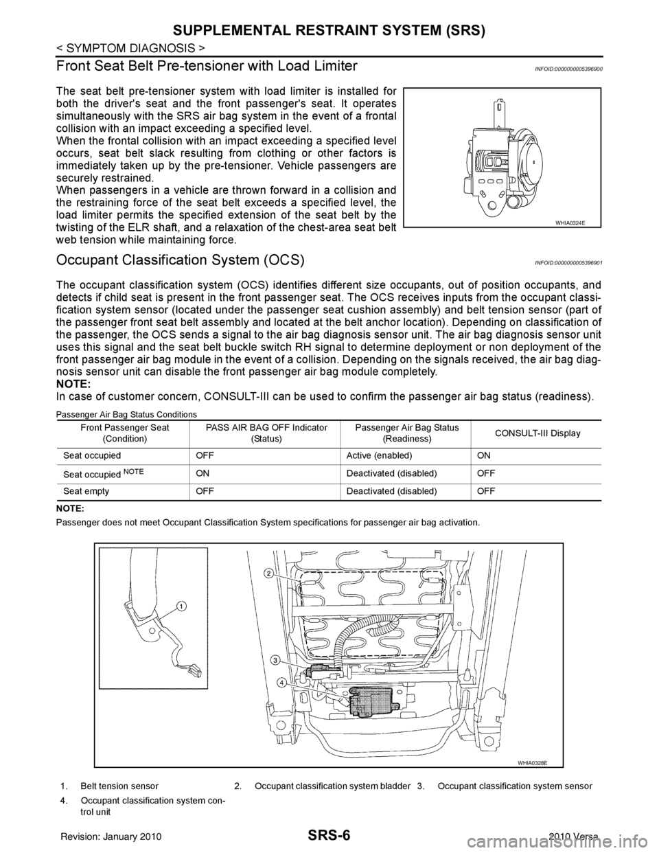
The seat belt pre-tensioner system wi th load limiter is installed for
both the driver's seat and the front passenger's seat. It operates
simultaneously with the SRS air bag system in the event of a frontal
collision with an impact exceeding a specified level.
When the frontal collision with an im pact exceeding a specified level
occurs, seat belt slack resulting from clothing or other factors is
immediately taken up by the pre-tensioner. Vehicle passengers are
securely restrained.
When passengers in a vehicle are thrown forward in a collision and
the restraining force of the seat belt exceeds a specified level, the
load limiter permits the specified extension of the seat belt by the
twisting of the ELR shaft, and a relaxation of the chest-area seat belt
web tension while maintaining force.
Occupant Classification System (OCS)INFOID:0000000005396901
The occupant classification system (OCS) identifies diff erent size occupants, out of position occupants, and
detects if child seat is present in the front passenger seat. The OCS receives inputs from the occupant classi-
fication system sensor (located under the passenger seat cushion assembly) and belt tension sensor (part of
the passenger front seat belt assembly and located at the belt anchor location). Depending on classification of
the passenger, the OCS sends a signal to the air bag di agnosis sensor unit. The air bag diagnosis sensor unit
uses this signal and the seat belt buckle switch RH signal to determine deployment or non deployment of the
front passenger air bag module in the event of a collision. Depending on the signals received, the air bag diag-
nosis sensor unit can disable the front passenger air bag module completely.
NOTE:
In case of customer concern, CONSULT-III can be used to confirm the passenger air bag status (readiness).
Passenger Air Bag Status Conditions
NOTE:
Passenger does not meet Occupant Classification System specifications for passenger air bag activation.
WHIA0324E
Front Passenger Seat
(Condition) PASS AIR BAG OFF Indicator
(Status) Passenger Air Bag Status
(Readiness) CONSULT-III Display
Seat occupied OFF Active (enabled)ON
Seat occupied
NOTEON Deactivated (disabled) OFF
Seat empty OFF Deactivated (disabled) OFF
1. Belt tension sensor 2. Occupant classification system bladder 3. Occupant classification system sensor
4. Occupant classification system con- trol unit
WHIA0328E
Revision: January 20102010 Versa
Page 3601 of 3745
SRS-8
< SYMPTOM DIAGNOSIS >
TROUBLE DIAGNOSIS
TROUBLE DIAGNOSIS
Trouble Diagnosis IntroductionINFOID:0000000005396903
CAUTION:
• Do not use electrical test equipment on any circuit related to the SRS unless instructed to do so in
this Service Manual.
• Do not attempt to repair, splice or modify SRS wiring harnesses. If a harness is damaged, replace it
with a new one.
• Keep ground connections clean.
DIAGNOSIS FUNCTION
The SRS self-diagnosis results can be read by usi ng “AIR BAG” warning lamp and/or CONSULT-III.
The User mode is exclusively prepared for the customer (driver). This mode warns the driver of a system mal-
function through the operation of the “AIR BAG” warning lamp.
The Diagnosis mode allows the technician to locate and inspect the malfunctioning part.
The mode applications for the “AIR BAG” warning lamp and CONSULT-III are as follows:
HOW TO PERFORM TROUBLE DIAGNOSES FOR QUICK AND ACCURATE REPAIR
A good understanding of the malfunction conditions can make troubleshooting faster and more accurate.
In general, each customer feels differently about a malf unction. It is important to fully understand the symp-
toms or conditions for a customer complaint.
Information From Customer
WHAT - Vehicle model
WHEN - Date, Frequencies
WHERE - Road conditions
HOW - Operating conditions, Symptoms
Preliminary Check
Check that the following parts are in good order.
• Battery (Refer to SC-5, "
How to Handle Battery".)
• Fuses (Refer to SRS-11, "
Schematic".)
• System component-to-harness connections
WORK FLOW
User mode Diagnosis mode Display type
“AIR BAG” warning lamp XXON-OFF operation
CONSULT-III —XMonitoring
Revision: January 20102010 Versa
Page 3613 of 3745
SRS-20
< SYMPTOM DIAGNOSIS >
TROUBLE DIAGNOSIS
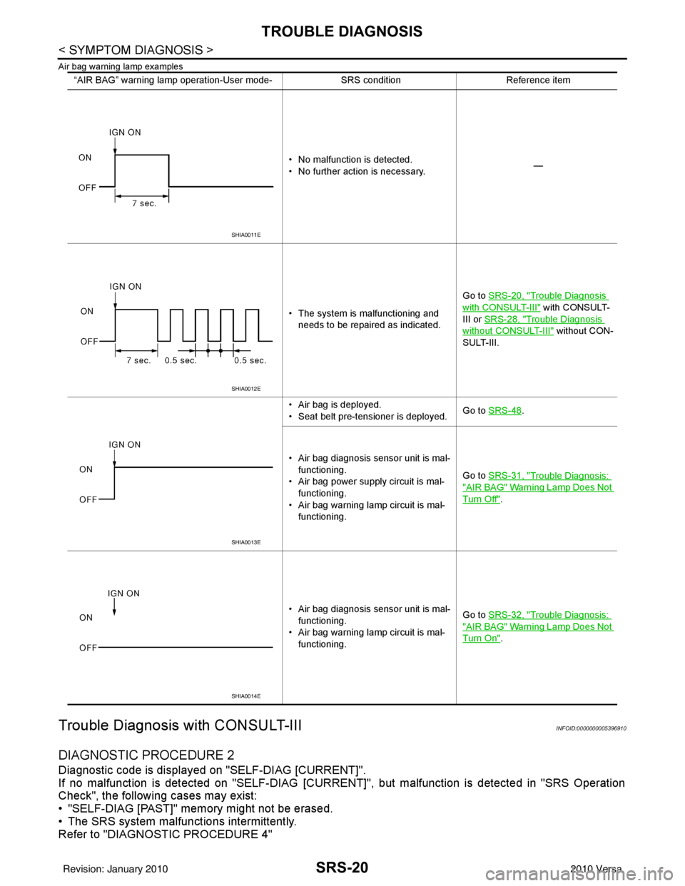
Air bag warning lamp examples
Trouble Diagnosis with CONSULT-IIIINFOID:0000000005396910
DIAGNOSTIC PROCEDURE 2
Diagnostic code is displayed on "SELF-DIAG [CURRENT]".
If no malfunction is detected on "SEL F-DIAG [CURRENT]", but malfunction is detected in "SRS Operation
Check", the following cases may exist:
• "SELF-DIAG [PAST]" memory might not be erased.
• The SRS system malfunctions intermittently.
Refer to "DIAGNOSTIC PROCEDURE 4"
“AIR BAG” warning lamp operation-User mode- SRS conditionReference item
• No malfunction is detected.
• No further action is necessary. —
• The system is malfunctioning and needs to be repaired as indicated. Go to
SRS-20, "
Trouble Diagnosis
with CONSULT-III" with CONSULT-
III or SRS-28, "
Trouble Diagnosis
without CONSULT-III" without CON-
SULT-III.
• Air bag is deployed.
• Seat belt pre-tensioner is deployed. Go to
SRS-48
.
• Air bag diagnosis sensor unit is mal- functioning.
• Air bag power supply circuit is mal- functioning.
• Air bag warning lamp circuit is mal- functioning. Go to
SRS-31, "
Trouble Diagnosis:
"AIR BAG" Warning Lamp Does Not
Turn Off".
• Air bag diagnosis sensor unit is mal- functioning.
• Air bag warning lamp circuit is mal- functioning. Go to
SRS-32, "
Trouble Diagnosis:
"AIR BAG" Warning Lamp Does Not
Turn On".
SHIA0011E
SHIA0012E
SHIA0013E
SHIA0014E
Revision: January 20102010 Versa
Page 3625 of 3745
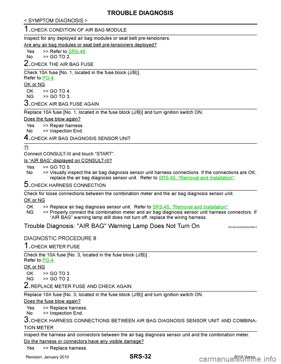
SRS-32
< SYMPTOM DIAGNOSIS >
TROUBLE DIAGNOSIS
1.CHECK CONDITION OF AIR BAG MODULE
Inspect for any deployed air bag modules or seat belt pre-tensioners.
Are any air bag modules or s eat belt pre-tensioners deployed?
Yes >> Refer to SRS-48.
No >> GO TO 2.
2.CHECK THE AIR BAG FUSE
Check 10A fuse [No. 1, locat ed in the fuse block (J/B)].
Refer to PG-4
.
OK or NG
OK >> GO TO 4.
NG >> GO TO 3.
3.CHECK AIR BAG FUSE AGAIN
Replace 10A fuse [No. 1, located in the fu se block (J/B)] and turn ignition switch ON.
Does the fuse blow again?
Yes >> Repair harness.
No >> Inspection End.
4.CHECK AIR BAG DIAGNOSIS SENSOR UNIT
Connect CONSULT-III and touch “START”.
Is
“AIR BAG” displayed on CONSULT-III?
Ye s > > G O T O 5 .
No >> Visually inspect the air bag diagnosis sensor unit harness connections. If the connections are OK,
replace the air bag diagnosis sensor unit. Refer to SRS-45, "
Removal and Installation".
5.CHECK HARNESS CONNECTION
Check for loose connections between the combination meter and the air bag diagnosis sensor unit.
OK or NG
OK >> Replace air bag diagnosis sensor unit. Refer to SRS-45, "Removal and Installation".
NG >> Properly connect the combination meter and ai r bag diagnosis sensor unit harness connectors. If
“AIR BAG” warning lamp still does not turn off, replace the wiring harness.
Trouble Diagnosis: "AIR BAG" Warning Lamp Does Not Turn OnINFOID:0000000005396913
DIAGNOSTIC PROCEDURE 8
1.CHECK METER FUSE
Check the 10A fuse [No. 3, located in the fuse block (J/B)] .
Refer to PG-4
.
OK or NG
OK >> GO TO 3.
NG >> GO TO 2.
2.REPLACE METER FUSE AND CHECK AGAIN
Replace 10A fuse [No. 3, located in the fu se block (J/B)] and turn ignition switch ON.
Does the fuse blow again?
Yes >> Replace harness.
No >> Inspection End.
3.CHECK HARNESS CONNECTIONS BET WEEN AIR BAG DIAGNOSIS SENSOR UNIT AND COMBINA-
TION METER
Inspect the harness and connectors between the air bag diagnosis sensor unit and the combination meter.
Do the harness or connectors have any visible damage?
Yes >> Replace harness.
Revision: January 20102010 Versa
Page 3649 of 3745
![NISSAN LATIO 2010 Service Repair Manual DIAGNOSIS AND REPAIR WORKFLOWSTC-3
< BASIC INSPECTION > [EPS]
C
D
E
F
H I
J
K L
M A
B
STC
N
O P
BASIC INSPECTION
DIAGNOSIS AND REPAIR WORKFLOW
Work FlowINFOID:0000000005600155
1.OBTAIN INFORMATION ABO NISSAN LATIO 2010 Service Repair Manual DIAGNOSIS AND REPAIR WORKFLOWSTC-3
< BASIC INSPECTION > [EPS]
C
D
E
F
H I
J
K L
M A
B
STC
N
O P
BASIC INSPECTION
DIAGNOSIS AND REPAIR WORKFLOW
Work FlowINFOID:0000000005600155
1.OBTAIN INFORMATION ABO](/manual-img/5/57358/w960_57358-3648.png)
DIAGNOSIS AND REPAIR WORKFLOWSTC-3
< BASIC INSPECTION > [EPS]
C
D
E
F
H I
J
K L
M A
B
STC
N
O P
BASIC INSPECTION
DIAGNOSIS AND REPAIR WORKFLOW
Work FlowINFOID:0000000005600155
1.OBTAIN INFORMATION ABOUT SYMPTOM
Interview the customer to obtain as much informa tion as possible about the conditions and environment under
which the malfunction occurs.
>> GO TO 2.
2.CHECK DTC
1. Check for DTC.
2. If a DTC exists, perform the following operations.
- Records the DTCs.
- Erase DTCs
- Check that the root cause clarified with DTC matches to the malfunction information described by the cus-
tomer.
3. Check also the related service information or others.
Do malfunction information or DTC exist?
Malfunction information and DTC exist. >>GO TO 3.
Malfunction information exists but no DTC. >>GO TO 4.
No malfunction information, but DTC exists. >>GO TO 5.
3.REPRODUCE THE MALFUNCTION INFORMATION
Check the malfunction described by the customer on the vehicle.
Record the status of each signal when a symptom occurs with “Data Monitor” in CONSULT-III.
Inspect the relation of the information and the condition when it occurs.
>> GO TO 5.
4.CHECK THE MALFUNCTION
Check the malfunction described by the customer on the vehicle.
Record the status of each signal when a symptom occurs with “Data Monitor” in CONSULT-III.
Inspect the relation of the information and the condition when it occurs.
>> GO TO 6.
5.PERFORM “DTC CONFIRMATION PROCEDURE”
Perform the “DTC conformation procedure” to the det ected DTC and check that the DTC is detected again.
Refer to STC-24, "
DTC Inspection Priority Chart" when multiple DTCs are detected, and then judge the order
for performing the diagnosis.
Is any DTC detected?
YES >> GO TO 7.
NO >> Follow GI-9, "
How to Follow Trouble Diagnosis" to check.
6.IDENTIFY MALFUNCTIONING SYST EM WITH “SYMPTOM DIAGNOSIS”
Use the “Symptom diagnosis” from the symptom inspection result in step 4. Then identify where to start per-
forming the diagnosis based on the pos sible causes and the symptoms.
>> GO TO 7.
7.IDENTIFY MALFUNCTIONING PART S WITH “COMPONENT DIAGNOSIS”
Perform the inspection with the “component diagnosis” of the applicable system.
NOTE:
The “component diagnosis” mainly consists of the check for an open circuit.
Revision: January 20102010 Versa