2010 NISSAN LATIO air condition
[x] Cancel search: air conditionPage 3301 of 3745

MTC-22
< SERVICE INFORMATION >
TROUBLE DIAGNOSIS
TROUBLE DIAGNOSIS
CONSULT-III Function (BCM)INFOID:0000000005598079
CONSULT-III can display each diagnostic item using the diagnostic test modes shown following.
ITEMS OF EACH PART
NOTE:
CONSULT-III will only display systems the vehicle possesses.
BCM diagnostic
test item Diagnostic mode
Content
Inspection by part WORK SUPPORT
Supports inspections and adjustments. Commands are transmitted to the BCM for
setting the status suitable for required operation, input/output signals are received
from the BCM and received data is displayed.
DATA MONITOR Displays BCM input/output data in real time. ACTIVE TEST Operation of electrical loads can be checked by sending drive signal to them.
SELF-DIAG RESULTS Displays BCM self-diagnosis results. CAN DIAG SUPPORT MNTR The results of transmit/receive diagnosis of CAN communication can be read.
ECU PART NUMBER BCM part number can be read. CONFIGURATION Performs BCM configuration read/write functions.
System and item CONSULT-III dis-
play Diagnostic test mode (Inspection by part)
WORK
SUPPORT SELF
−
DIAG RE-
SULTS CAN DIAG
SUPPORT
MNTR DATA
MONITOR ECU
PA R T
NUMBER AC-
TIVE
TEST CON-
FIGU-
RATION
BCM BCM×× × × ×
Power door lock sys-
tem DOOR LOCK
×× ×
Rear defogger REAR DEFOG-
GER ××
Warning chime BUZZER ××
Room lamp timer INT LAMP ×× ×
Remote keyless entry
system MULTI REMOTE
ENT
××
×
Headlamp HEAD LAMP×× ×
Wiper WIPER×× ×
Turn signal lamp
Hazard lamp FLASHER
××
Blower fan switch sig-
nal
Air conditioner switch
signal AIR CONDITION-
ER
×
Intelligent Key INTELLIGENT
KEY ×
Combination switch COMB SW ×
NVIS (NATS) IMMU ××
Interior lamp battery
saver BATTERY SAV-
ER
××
×
Back door/Trunk TRUNK ××
Theft alarm THEFT ALARM×× ×
Revision: January 20102010 Versa
Page 3316 of 3745
TROUBLE DIAGNOSISMTC-37
< SERVICE INFORMATION >
C
DE
F
G H
I
K L
M A
B
MTC
N
O P
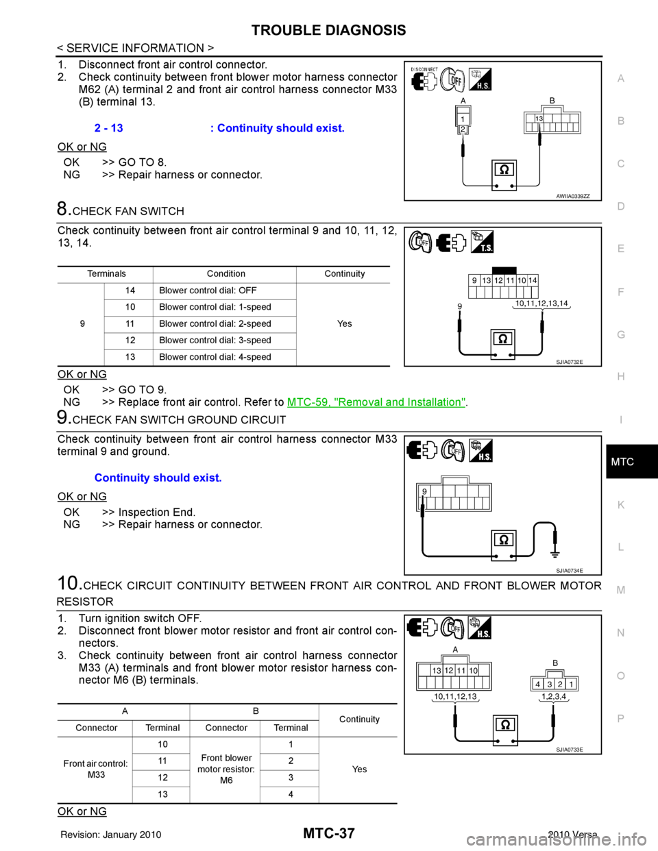
1. Disconnect front air control connector.
2. Check continuity between front blower motor harness connector M62 (A) terminal 2 and front air control harness connector M33
(B) terminal 13.
OK or NG
OK >> GO TO 8.
NG >> Repair harness or connector.
8.CHECK FAN SWITCH
Check continuity between front ai r control terminal 9 and 10, 11, 12,
13, 14.
OK or NG
OK >> GO TO 9.
NG >> Replace front air control. Refer to MTC-59, "
Removal and Installation".
9.CHECK FAN SWITCH GROUND CIRCUIT
Check continuity between front air control harness connector M33
terminal 9 and ground.
OK or NG
OK >> Inspection End.
NG >> Repair harness or connector.
10.CHECK CIRCUIT CONTINUITY BETWEEN FRONT AIR CONTROL AND FRONT BLOWER MOTOR
RESISTOR
1. Turn ignition switch OFF.
2. Disconnect front blower motor resistor and front air control con- nectors.
3. Check continuity between front air control harness connector
M33 (A) terminals and front blower motor resistor harness con-
nector M6 (B) terminals.
OK or NG
2 - 13 : Continuity should exist.
AWIIA0339ZZ
Terminals ConditionContinuity
9 14 Blower control dial: OFF
Ye s
10 Blower control dial: 1-speed
11 Blower control dial: 2-speed
12 Blower control dial: 3-speed
13 Blower control dial: 4-speed
SJIA0732E
Continuity should exist.
SJIA0734E
AB Continuity
Connector Terminal Connector Terminal
Front air control: M33 10
Front blower
motor resistor: M6 1
Ye s
11
2
12 3
13 4
SJIA0733E
Revision: January 20102010 Versa
Page 3317 of 3745
MTC-38
< SERVICE INFORMATION >
TROUBLE DIAGNOSIS
OK >> GO TO 11.
NG >> Repair harness or connector.
11 .CHECK FAN SWITCH
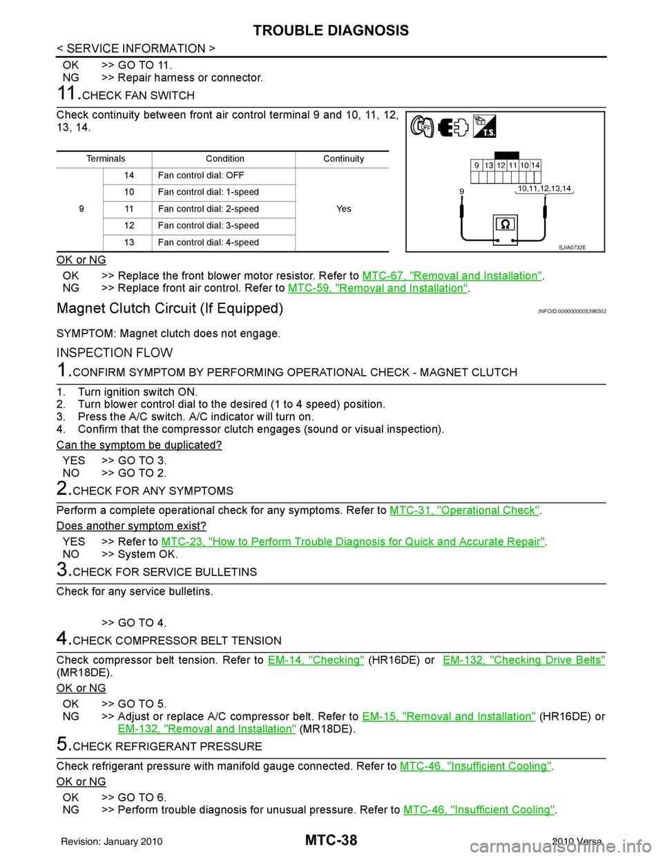
Check continuity between front air control terminal 9 and 10, 11, 12,
13, 14.
OK or NG
OK >> Replace the front blower motor resistor. Refer to MTC-67, "Removal and Installation".
NG >> Replace front air control. Refer to MTC-59, "
Removal and Installation".
Magnet Clutch Circuit (If Equipped)INFOID:0000000005396502
SYMPTOM: Magnet clutch does not engage.
INSPECTION FLOW
1.CONFIRM SYMPTOM BY PERFORMING OP ERATIONAL CHECK - MAGNET CLUTCH
1. Turn ignition switch ON.
2. Turn blower control dial to the desired (1 to 4 speed) position.
3. Press the A/C switch. A/C indicator will turn on.
4. Confirm that the compressor clut ch engages (sound or visual inspection).
Can the symptom be duplicated?
YES >> GO TO 3.
NO >> GO TO 2.
2.CHECK FOR ANY SYMPTOMS
Perform a complete operational check for any symptoms. Refer to MTC-31, "
Operational Check".
Does another symptom exist?
YES >> Refer to MTC-23, "How to Perform Trouble Diagnosis for Quick and Accurate Repair".
NO >> System OK.
3.CHECK FOR SERVICE BULLETINS
Check for any service bulletins.
>> GO TO 4.
4.CHECK COMPRESSOR BELT TENSION
Check compressor belt tension. Refer to EM-14, "
Checking" (HR16DE) or EM-132, "Checking Drive Belts"
(MR18DE).
OK or NG
OK >> GO TO 5.
NG >> Adjust or replace A/C compressor belt. Refer to EM-15, "
Removal and Installation" (HR16DE) or
EM-132, "
Removal and Installation" (MR18DE).
5.CHECK REFRIGERANT PRESSURE
Check refrigerant pressure with manifold gauge connected. Refer to MTC-46, "
Insufficient Cooling".
OK or NG
OK >> GO TO 6.
NG >> Perform trouble diagnosis for unusual pressure. Refer to MTC-46, "
Insufficient Cooling".
TerminalsConditionContinuity
9 14 Fan control dial: OFF
Ye s
10 Fan control dial: 1-speed
11 Fan control dial: 2-speed
12 Fan control dial: 3-speed
13 Fan control dial: 4-speed
SJIA0732E
Revision: January 20102010 Versa
Page 3329 of 3745

MTC-50
< SERVICE INFORMATION >
TROUBLE DIAGNOSIS
Testing must be performed as follows:
TEST READING
Recirculating-to-discharge Air Temperature Table
Ambient Air Temperature-to-operating Pressure Table
*1: With blower control dial in the "1" position
*2: With blower control dial in the "4" position.
TROUBLE DIAGNOSIS FOR ABNORMAL PRESSURE
Whenever system’s high and/or low side pressure(s) is/are abnormal, diagnose using a manifold gauge. The
marker above the gauge scale in the following tables indicates the standard (usual) pressure range. Since the
standard (usual) pressure, however, differs from vehicle to vehicle, refer to above table (Ambient air tempera-
ture-to-operating pressure table).
Vehicle condition Indoors or in the shade (in a well-ventilated place)
Doors Closed
Door window Open
Hood Open
TEMP. Max. COLD
Mode control dial (Ventilation) set
Intake door lever (Recirculation) set
Blower speed Max. speed set
Engine speed Idle speed
Operate the air conditioning system for 10 minutes before taking measurements.
Inside air (Recirculating air) at blower assembly inlet Discharge air temperature at center ventilator
°C ( °F)
Relative humidity
% Air temperature
°C ( °F)
50 - 60 20 (68)
7.2 - 9.1 (45 - 48)
25 (77) 11.4 - 13.8 (53 - 57)
30 (86) 15.5 - 18.4 (60 - 65)
35 (95) 20.3 - 23.7 (69 - 75)
60 - 70 20 (68)
9.1 - 10.9 (48 - 52)
25 (77) 13.8 - 16.2 (57 - 61)
30 (86) 18.4 - 21.3 (65 - 70)
35 (95) 23.7 - 27.1 (75 - 81)
Ambient air
High-pressure (Discharge side)
kPa (bar, kg/cm
2 , psi) Low-pressure (Suction side)
kPa (bar, kg/cm2 , psi)
Relative humidity
% Air temperature
°C ( °F)
50 - 70 20 (68)
843 - 1,036 *1
(11.08 - 13.63, 8.6 - 10.6, 122 - 150) 159.0 - 194.0
(1.59 - 1.94, 1.62 - 1.98, 23.1 - 28.1)
25 (77) 1,094 - 1,338 *1
(10.94 - 13.38, 11.2 - 13.6, 159 - 194) 196.3 - 240.0
(1.96 - 2.40, 2.00 - 2.45, 28.5 - 34.8)
30 (86) 1,298 - 1,590 *1
(12.98 - 15.90, 13.2 - 16.2, 188 - 231) 248.0 - 302.7
(2.48 - 3.03, 2.53 - 3.09, 36.0 - 43.9)
35 (95) 1,383 - 1,688 *2
(13.83 - 16.88, 14.1 - 17.2, 201 - 245) 308.8 - 377.4
(3.09 - 3.77, 3.15 - 3.85, 44.8 - 54.7)
40 (104) 1,628 - 1,988 *2
(16.28 - 19.88, 16.6 - 20.3, 236 - 288) 377.4 - 461.2
(3.77 - 4.61, 3.85 - 4.70, 54.7 - 66.8)
Revision: January 20102010 Versa
Page 3331 of 3745
MTC-52
< SERVICE INFORMATION >
TROUBLE DIAGNOSIS
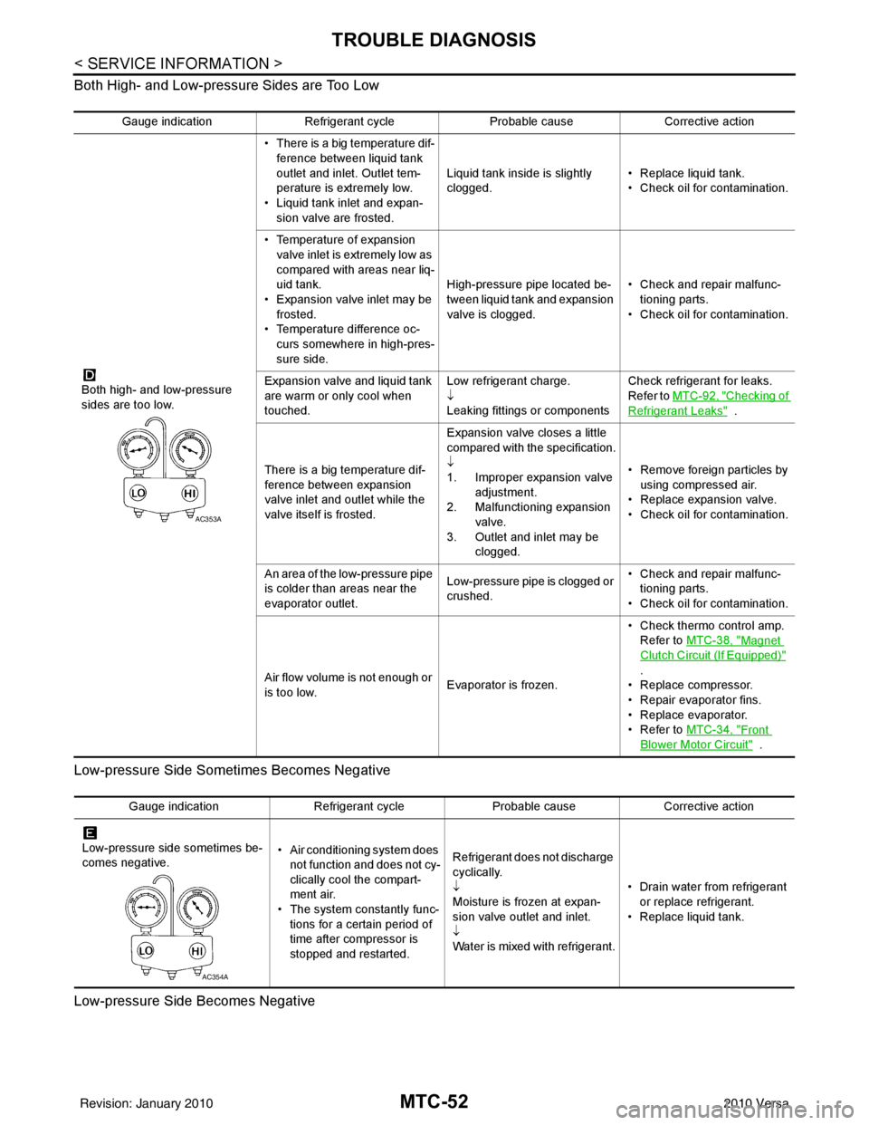
Both High- and Low-pressure Sides are Too Low
Low-pressure Side Sometimes Becomes Negative
Low-pressure Side Becomes Negative
Gauge indication Refrigerant cycle Probable causeCorrective action
Both high- and low-pressure
sides are too low. • There is a big temperature dif-
ference between liquid tank
outlet and inlet. Outlet tem-
perature is extremely low.
• Liquid tank inlet and expan- sion valve are frosted. Liquid tank inside is slightly
clogged.
• Replace liquid tank.
• Check oil for contamination.
• Temperature of expansion valve inlet is extremely low as
compared with areas near liq-
uid tank.
• Expansion valve inlet may be
frosted.
• Temperature difference oc- curs somewhere in high-pres-
sure side. High-pressure pipe located be-
tween liquid tank and expansion
valve is clogged.
• Check and repair malfunc-
tioning parts.
• Check oil for contamination.
Expansion valve and liquid tank
are warm or only cool when
touched. Low refrigerant charge.
↓
Leaking fittings or componentsCheck refrigerant for leaks.
Refer to
MTC-92, "
Checking of
Refrigerant Leaks" .
There is a big temperature dif-
ference between expansion
valve inlet and outlet while the
valve itself is frosted. Expansion valve closes a little
compared with the specification.
↓
1. Improper expansion valve
adjustment.
2. Malfunctioning expansion valve.
3. Outlet and inlet may be clogged. • Remove foreign particles by
using compressed air.
• Replace expansion valve.
• Check oil for contamination.
An area of the low-pressure pipe
is colder than areas near the
evaporator outlet. Low-pressure pipe is clogged or
crushed.• Check and repair malfunc-
tioning parts.
• Check oil for contamination.
Air flow volume is not enough or
is too low. Evaporator is frozen.• Check thermo control amp.
Refer to MTC-38, "
Magnet
Clutch Circuit (If Equipped)"
.
• Replace compressor.
• Repair evaporator fins.
• Replace evaporator.
•Refer to MTC-34, "
Front
Blower Motor Circuit" .
AC353A
Gauge indication Refrigerant cycleProbable causeCorrective action
Low-pressure side sometimes be-
comes negative. • Air conditioning system does
not function and does not cy-
clically cool the compart-
ment air.
• The system constantly func-
tions for a certain period of
time after compressor is
stopped and restarted. Refrigerant does not discharge
cyclically.
↓
Moisture is frozen at expan-
sion valve outlet and inlet.
↓
Water is mixed with refrigerant.
• Drain water from refrigerant
or replace refrigerant.
• Replace liquid tank.
AC354A
Revision: January 20102010 Versa
Page 3340 of 3745

A/C UNIT ASSEMBLYMTC-61
< SERVICE INFORMATION >
C
DE
F
G H
I
K L
M A
B
MTC
N
O P
Disassembly and AssemblyINFOID:0000000005396510
1. Blower case (right) 2. Foot duct (right) 3. Blower motor
4. Sub ventilator·defroster door lever 5. Sub ventilator·defroster door rod 6. Ventilator·defroster door lever
7. Ventilator·defroster door rod 8. Intake door lever 9. Ventilator·defroster door link
10. Main link 11. Thermo control amp.
(MR18DE - TYPE1) 12. Heater pipe packing
13. Lower blower case 14. Heater pipe cover 15. Heater pipe clip
16. Intake door link 17. Blower fan resistor 18. Intake case (left)
19. Center defroster duct 20. Blower case (left) 21. Cover
22. Cover 23. Expansion valve cover 24. Foot door lever
25. Foot door link 26. Expansion valve 27. Air conditioner filter
28. Evaporator cover 29. Heater core 30. Spring
31. Water valve rod 32. Air mix door lever 33. Intake door
34. Intake case (right) 35. Foot duct (left) 36. Ventilator·defroster door
37. Foot door 38. Air mix door 39. Seal
SJIA1515E
Revision: January 20102010 Versa
Page 3348 of 3745
AIR CONDITIONER FILTERMTC-69
< SERVICE INFORMATION >
C
DE
F
G H
I
K L
M A
B
MTC
N
O P
AIR CONDITIONER FILTER
Removal and InstallationINFOID:0000000005396517
FUNCTION
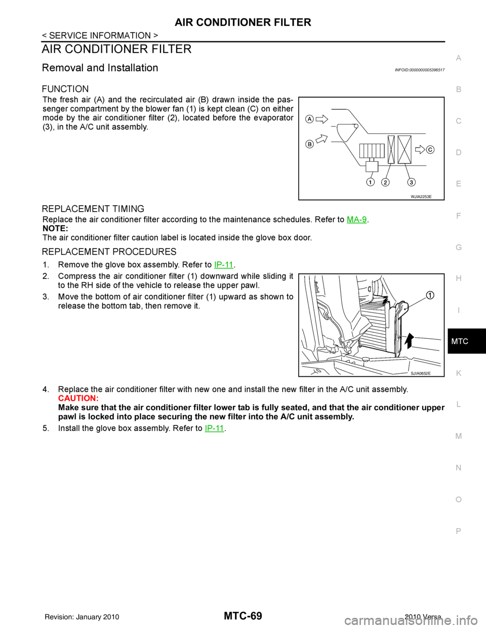
The fresh air (A) and the recirculated air (B) drawn inside the pas-
senger compartment by the blower fan (1) is kept clean (C) on either
mode by the air conditioner filter (2), located before the evaporator
(3), in the A/C unit assembly.
REPLACEMENT TIMING
Replace the air conditioner filter according to the maintenance schedules. Refer to MA-9.
NOTE:
The air conditioner filter caution label is located inside the glove box door.
REPLACEMENT PROCEDURES
1. Remove the glove box assembly. Refer to IP-11.
2. Compress the air conditioner filter (1) downward while sliding it to the RH side of the vehicle to release the upper pawl.
3. Move the bottom of air conditioner filter (1) upward as shown to
release the bottom tab, then remove it.
4. Replace the air conditioner filter with new one and in stall the new filter in the A/C unit assembly.
CAUTION:
Make sure that the air cond itioner filter lower tab is fully seated, and that the air conditioner upper
pawl is locked into place securing the new filter into the A/C unit assembly.
5. Install the glove box assembly. Refer to IP-11
.
WJIA2253E
SJIA0652E
Revision: January 20102010 Versa
Page 3370 of 3745
REFRIGERANT LINESMTC-91
< SERVICE INFORMATION >
C
DE
F
G H
I
K L
M A
B
MTC
N
O P
4. Remove liquid tank bracket (1 ) from protruding part of con-
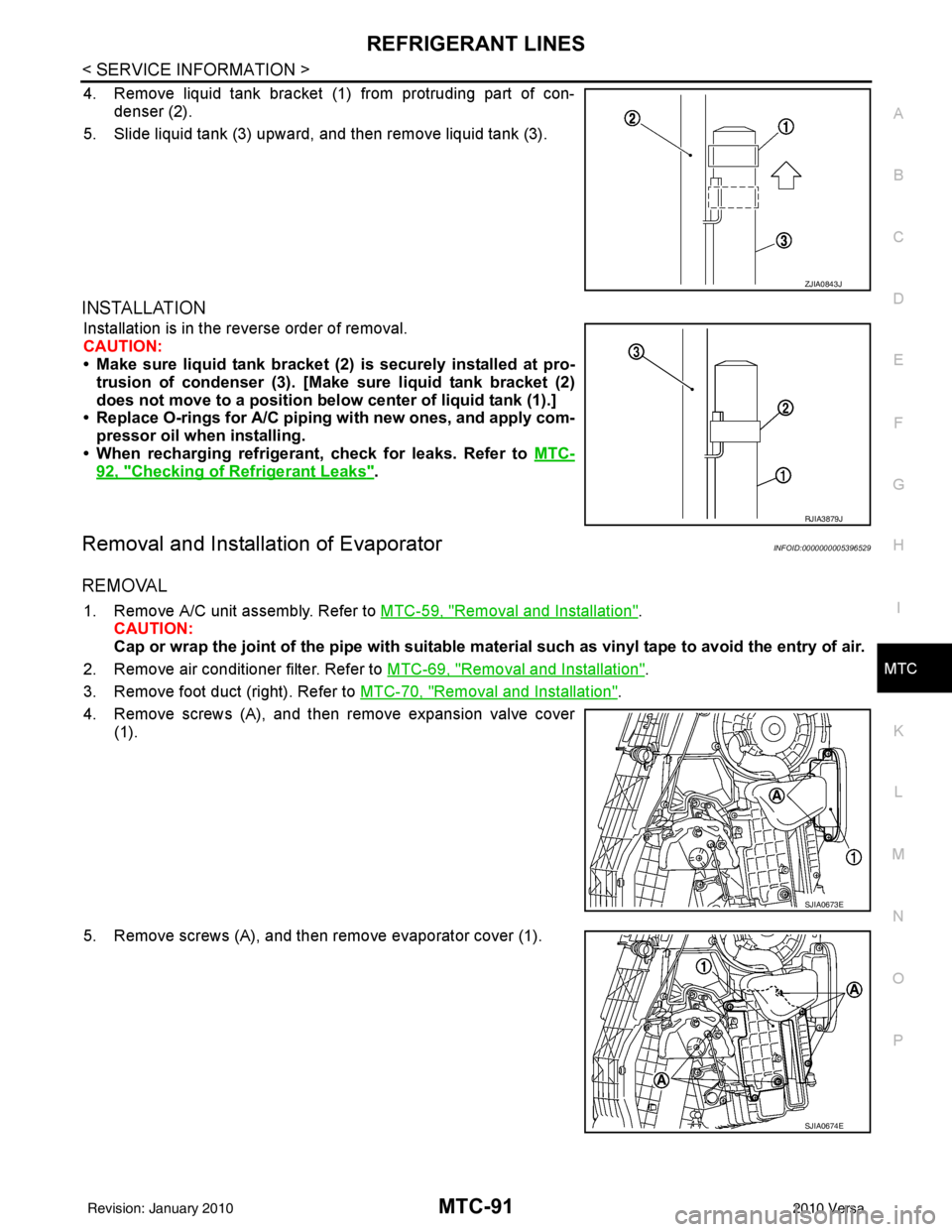
denser (2).
5. Slide liquid tank (3) upward, and then remove liquid tank (3).
INSTALLATION
Installation is in the reverse order of removal.
CAUTION:
• Make sure liquid tank bracket (2) is securely installed at pro- trusion of condenser (3). [Make sure liquid tank bracket (2)
does not move to a position belo w center of liquid tank (1).]
• Replace O-rings for A/C piping with new ones, and apply com-
pressor oil when installing.
• When recharging refrigerant, check for leaks. Refer to MTC-
92, "Checking of Refrigerant Leaks".
Removal and Installation of EvaporatorINFOID:0000000005396529
REMOVAL
1. Remove A/C unit assembly. Refer to MTC-59, "Removal and Installation".
CAUTION:
Cap or wrap the joint of the pipe with suitable ma terial such as vinyl tape to avoid the entry of air.
2. Remove air conditioner filter. Refer to MTC-69, "
Removal and Installation".
3. Remove foot duct (right). Refer to MTC-70, "
Removal and Installation".
4. Remove screws (A), and then remove expansion valve cover (1).
5. Remove screws (A), and then remove evaporator cover (1).
ZJIA0843J
RJIA3879J
SJIA0673E
SJIA0674E
Revision: January 20102010 Versa