2010 NISSAN LATIO air condition
[x] Cancel search: air conditionPage 3501 of 3745
TROUBLE DIAGNOSISRF-17
< FUNCTION DIAGNOSIS >
C
DE
F
G H
J
K L
M A
B
RF
N
O P
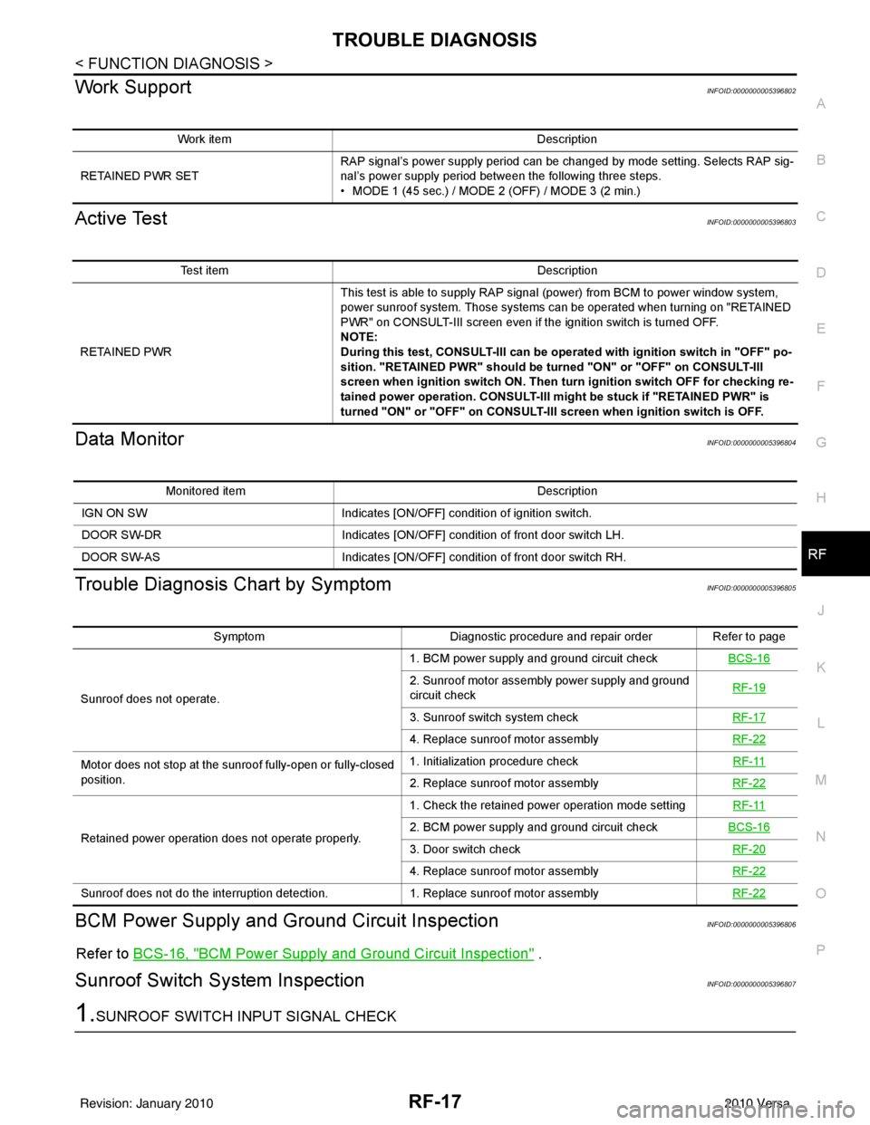
Work SupportINFOID:0000000005396802
Active TestINFOID:0000000005396803
Data MonitorINFOID:0000000005396804
Trouble Diagnosis Chart by SymptomINFOID:0000000005396805
BCM Power Supply and Gr ound Circuit InspectionINFOID:0000000005396806
Refer to BCS-16, "BCM Power Supply and Ground Circuit Inspection" .
Sunroof Switch System InspectionINFOID:0000000005396807
1.SUNROOF SWITCH INPUT SIGNAL CHECK
Work item Description
RETAINED PWR SET RAP signal’s power supply period can be changed by mode setting. Selects RAP sig-
nal’s power supply period between the following three steps.
• MODE 1 (45 sec.) / MODE 2 (OFF) / MODE 3 (2 min.)
Test item
Description
RETAINED PWR This test is able to supply RAP signal (power) from BCM to power window system,
power sunroof system. Those systems can be operated when turning on "RETAINED
PWR" on CONSULT-III screen even if the ignition switch is turned OFF.
NOTE:
During this test, CONSULT-III can be operated with ignition switch in "OFF" po-
sition. "RETAINED PWR" should be turned "ON" or "OFF" on CONSULT-III
screen when ignition switch ON. Then turn ignition switch OFF for checking re-
tained power operation. CONSULT-III might be stuck if "RETAINED PWR" is
turned "ON" or "OFF" on CONSULT-III screen when ignition switch is OFF.
Monitored item
Description
IGN ON SW Indicates [ON/OFF] condition of ignition switch.
DOOR SW-DR Indicates [ON/OFF] condition of front door switch LH.
DOOR SW-AS Indicates [ON/OFF] condition of front door switch RH.
SymptomDiagnostic procedure and repair order Refer to page
Sunroof does not operate. 1. BCM power supply and ground circuit check
BCS-16
2. Sunroof motor assembly power supply and ground
circuit check RF-19
3. Sunroof switch system check
RF-17
4. Replace sunroof motor assemblyRF-22
Motor does not stop at the sunroof fully-open or fully-closed
position. 1. Initialization procedure check
RF-11
2. Replace sunroof motor assemblyRF-22
Retained power operation does not operate properly. 1. Check the retained power operation mode setting
RF-112. BCM power supply and ground circuit checkBCS-16
3. Door switch check RF-20
4. Replace sunroof motor assemblyRF-22
Sunroof does not do the interruption detection. 1. Replace sunroof motor assemblyRF-22
Revision: January 20102010 Versa
Page 3502 of 3745
RF-18
< FUNCTION DIAGNOSIS >
TROUBLE DIAGNOSIS
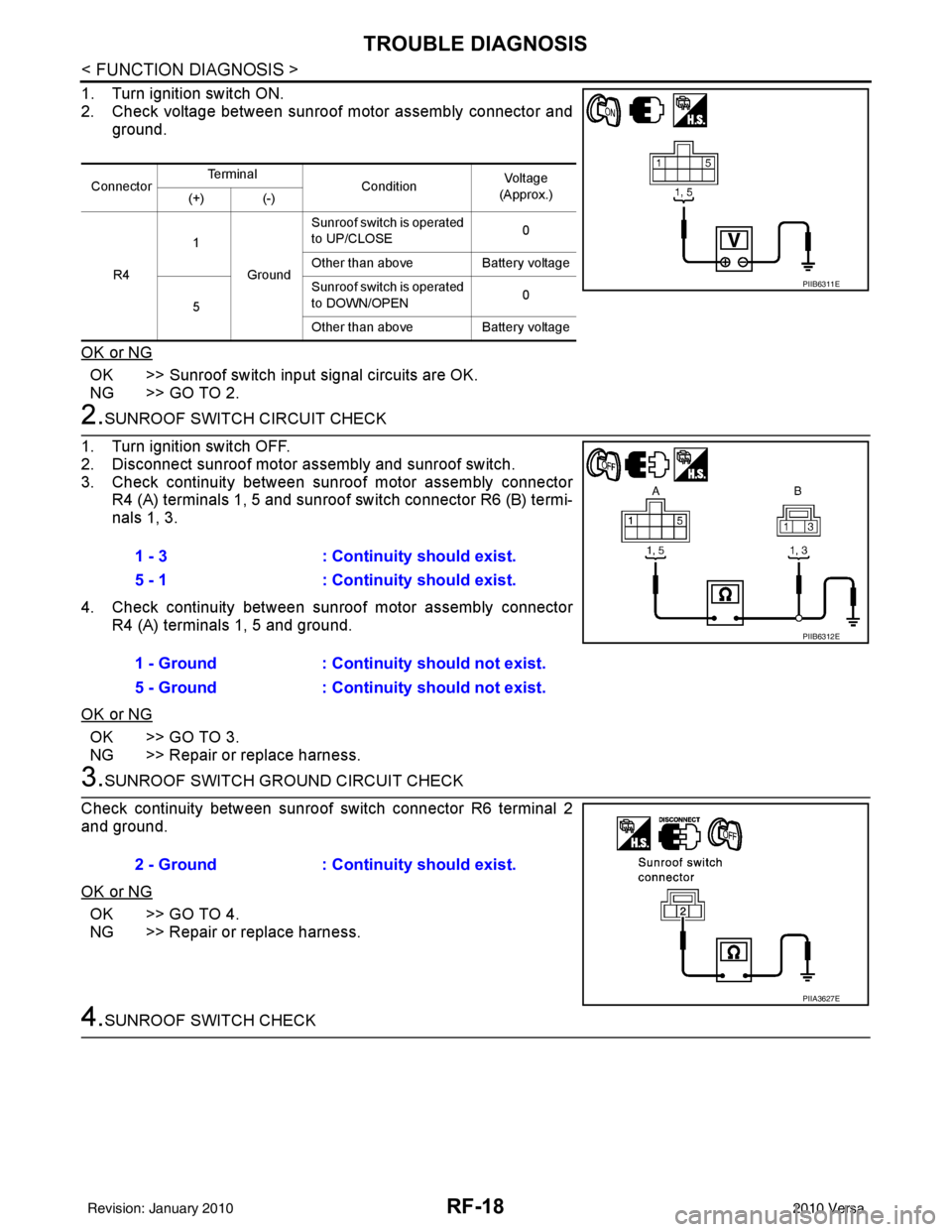
1. Turn ignition switch ON.
2. Check voltage between sunroof motor assembly connector andground.
OK or NG
OK >> Sunroof switch input signal circuits are OK.
NG >> GO TO 2.
2.SUNROOF SWITCH CIRCUIT CHECK
1. Turn ignition switch OFF.
2. Disconnect sunroof motor assembly and sunroof switch.
3. Check continuity between sunroof motor assembly connector R4 (A) terminals 1, 5 and sunroof switch connector R6 (B) termi-
nals 1, 3.
4. Check continuity between sunroof motor assembly connector R4 (A) terminals 1, 5 and ground.
OK or NG
OK >> GO TO 3.
NG >> Repair or replace harness.
3.SUNROOF SWITCH GROUND CIRCUIT CHECK
Check continuity between sunroof switch connector R6 terminal 2
and ground.
OK or NG
OK >> GO TO 4.
NG >> Repair or replace harness.
4.SUNROOF SWITCH CHECK
Connector Te r m i n a l
ConditionVol tag e
(Approx.)
(+) (-)
R4 1
Ground Sunroof switch is operated
to UP/CLOSE
0
Other than above Battery voltage
5 Sunroof switch is operated
to DOWN/OPEN
0
Other than above Battery voltage
PIIB6311E
1 - 3: Continuity should exist.
5 - 1 : Continuity should exist.
1 - Ground : Continuity should not exist.
5 - Ground : Continuity should not exist.
PIIB6312E
2 - Ground: Continuity should exist.
PIIA3627E
Revision: January 20102010 Versa
Page 3503 of 3745
TROUBLE DIAGNOSISRF-19
< FUNCTION DIAGNOSIS >
C
DE
F
G H
J
K L
M A
B
RF
N
O P
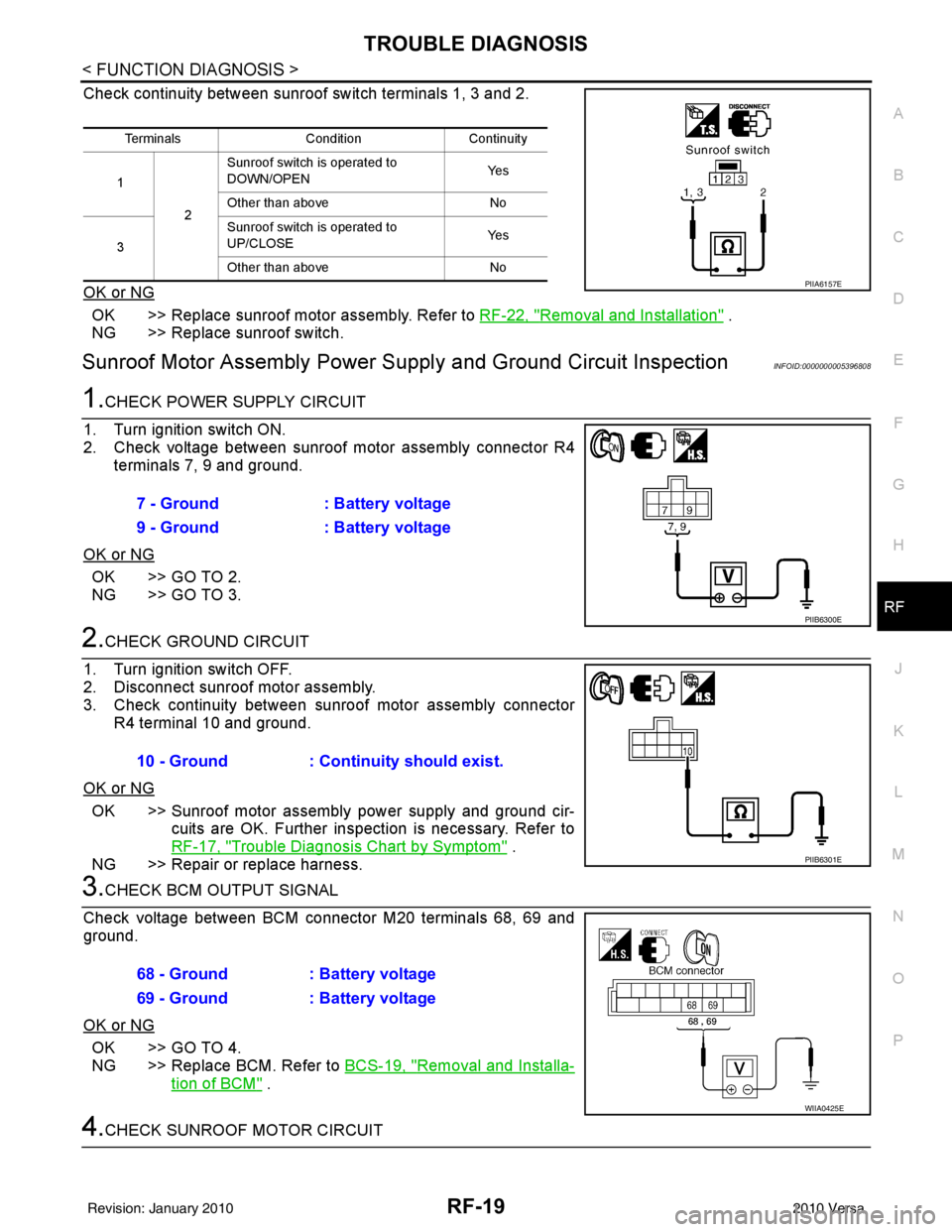
Check continuity between sunroof switch terminals 1, 3 and 2.
OK or NG
OK >> Replace sunroof motor assembly. Refer to RF-22, "Removal and Installation" .
NG >> Replace sunroof switch.
Sunroof Motor Assembly Power Supply and Ground Circuit InspectionINFOID:0000000005396808
1.CHECK POWER SUPPLY CIRCUIT
1. Turn ignition switch ON.
2. Check voltage between sunroof motor assembly connector R4 terminals 7, 9 and ground.
OK or NG
OK >> GO TO 2.
NG >> GO TO 3.
2.CHECK GROUND CIRCUIT
1. Turn ignition switch OFF.
2. Disconnect sunroof motor assembly.
3. Check continuity between sunroof motor assembly connector R4 terminal 10 and ground.
OK or NG
OK >> Sunroof motor assembly power supply and ground cir- cuits are OK. Further inspection is necessary. Refer to
RF-17, "
Trouble Diagnosis Chart by Symptom" .
NG >> Repair or replace harness.
3.CHECK BCM OUTPUT SIGNAL
Check voltage between BCM connector M20 terminals 68, 69 and
ground.
OK or NG
OK >> GO TO 4.
NG >> Replace BCM. Refer to BCS-19, "
Removal and Installa-
tion of BCM" .
4.CHECK SUNROOF MOTOR CIRCUIT
Terminals ConditionContinuity
1 2Sunroof switch is operated to
DOWN/OPEN
Ye s
Other than above No
3 Sunroof switch is operated to
UP/CLOSE
Ye s
Other than above No
PIIA6157E
7 - Ground: Battery voltage
9 - Ground : Battery voltage
PIIB6300E
10 - Ground: Continuity should exist.
PIIB6301E
68 - Ground : Battery voltage
69 - Ground : Battery voltage
WIIA0425E
Revision: January 20102010 Versa
Page 3504 of 3745
RF-20
< FUNCTION DIAGNOSIS >
TROUBLE DIAGNOSIS
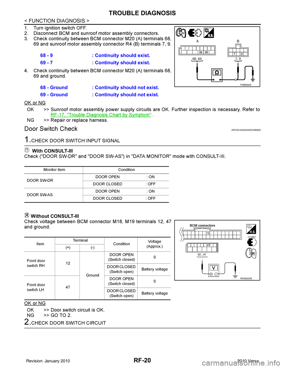
1. Turn ignition switch OFF.
2. Disconnect BCM and sunroof motor assembly connectors.
3. Check continuity between BCM connector M20 (A) terminals 68,
69 and sunroof motor assembly connector R4 (B) terminals 7, 9.
4. Check continuity between BCM connector M20 (A) terminals 68,
69 and ground.
OK or NG
OK >> Sunroof motor assembly power supply circuits are OK. Further inspection is necessary. Refer to
RF-17, "
Trouble Diagnosis Chart by Symptom" .
NG >> Repair or replace harness.
Door Switch CheckINFOID:0000000005396809
1.CHECK DOOR SWITCH INPUT SIGNAL
With CONSULT-III
Check ("DOOR SW-DR" and "DOOR SW-AS") in "DATA MONITOR" mode with CONSULT-III.
Without CONSULT-III
Check voltage between BCM connector M18, M19 terminals 12, 47
and ground.
OK or NG
OK >> Door switch circuit is OK.
NG >> GO TO 2.
2.CHECK DOOR SWITCH CIRCUIT 68 - 9
: Continuity should exist.
69 - 7 : Continuity should exist.
68 - Ground : Continuity should not exist.
69 - Ground : Continuity should not exist.
PIIB6302E
Monitor item Condition
DOOR SW-DR DOOR OPEN
: ON
DOOR CLOSED : OFF
DOOR SW-AS DOOR OPEN
: ON
DOOR CLOSED : OFF
ItemTe r m i n a l
ConditionVo l ta g e
(Approx.)
(+) (-)
Front door
switch RH 12
Ground DOOR OPEN
(Switch closed) 0
DOOR CLOSED (Switch open) Battery voltage
Front door
switch LH 47 DOOR OPEN
(Switch closed) 0
DOOR CLOSED (Switch open) Battery voltage
WIIA0234E
Revision: January 20102010 Versa
Page 3517 of 3745

PRECAUTIONSRSU-3
< SERVICE INFORMATION >
C
DF
G H
I
J
K L
M A
B
RSU
N
O P
5. When the repair work is completed, return the ignition switch to the ″LOCK ″ position before connecting
the battery cables. (At this time, the steering lock mechanism will engage.)
6. Perform a self-diagnosis check of al l control units using CONSULT-III.
Precaution for Rear SuspensionINFOID:0000000005397074
• When installing the rubber bushings, the final tightening must be done under unladen condition and with the
tires on level ground. Oil will shorten the life of the rubber bushings, so wipe off any spilled oil immediately.
• Unladen condition means the fuel tank, engine coolant and lubricants are at the full specification. The spare
tire, jack, hand tools, and mats are in their designated positions.
• After installing suspension components, check the wheel alignment.
• Caulking nuts are not reusable. Always use new caulking nuts for installation. New caulking nuts are pre- oiled, do not apply any additional lubrication.
Revision: January 20102010 Versa
Page 3520 of 3745
RSU-6
< SERVICE INFORMATION >
REAR SUSPENSION ASSEMBLY
REAR SUSPENSION ASSEMBLY
On-Vehicle Inspection and ServiceINFOID:0000000005397077
Make sure the mounting conditions (looseness, backlash) of each component and component conditions
(wear, damage) are within specifications.
SHOCK ABSORBER INSPECTION
Check shock absorber for oil leakage, damage and replace it if necessary.
Wheel AlignmentInspectionINFOID:0000000005397078
DESCRIPTION
Measure wheel alignment under unladen conditions.
NOTE:
“Unladen conditions” means that fuel, engine coolant, and lubricant are full. Spare tire, jack, hand tools and
mats are in designated positions.
PRELIMINARY
Check the following:
1. Tires for improper air pressure and wear.
2. Road wheels for runout. Refer to WT-6
.
3. Wheel bearing axial end play. Refer to RAX-6, "
On-Vehicle Inspection and Service" .
4. Shock absorber operation.
5. Each mounting part of suspension for looseness and deformation.
6. Rear suspension beam for cracks, deformation, and other damage.
7. Vehicle height (posture).
GENERAL INFORMATION AND RECOMMENDATIONS
1. A Four-Wheel Thrust Alignment should be performed. • This type of alignment is recommended for any NISSAN vehicle.
• The four-wheel “thrust” process helps ensure that the vehicle is properly aligned and the steering wheel
is centered.
• The alignment machine itself should be ca pable of accepting any NISSAN vehicle.
• The alignment machine should be checked to ensure that it is level.
2. Make sure the alignment machine is properly calibrated. • Your alignment machine should be regularly calibrated in order to give correct information.
• Check with the manufacturer of your specific al ignment machine for their recommended Service/Cali-
bration Schedule.
THE ALIGNMENT PROCESS
IMPORTANT: Use only the alignment specifications listed in this Service Manual. Refer to RSU-13, "Wheel
Alignment (Unladen*)" .
1. When displaying the alignment settings, many alignment machines use “indicators”: (Green/red, plus or minus, Go/No Go). Do NOT use these indicators.
• The alignment specifications programmed into your alignment machine that operate these indicators may not be correct.
• This may result in an ERROR.
2. Some newer alignment machines are equipped with an optional “Rolling Compensation” method to “com- pensate” the sensors (alignment targets or head units). Do NOT use this “Rolling Compensation”
method.
• Use the “Jacking Compensation” method. After inst alling the alignment targets or head units, raise the
vehicle and rotate the wheels 1/2 turn both ways.
• See Instructions in the alignment machine you are using for more information.
CAMBER INSPECTION
Revision: January 20102010 Versa
Page 3526 of 3745
RSU-12
< SERVICE INFORMATION >
REAR SUSPENSION BEAM
REAR SUSPENSION BEAM
Removal and InstallationINFOID:0000000005397082
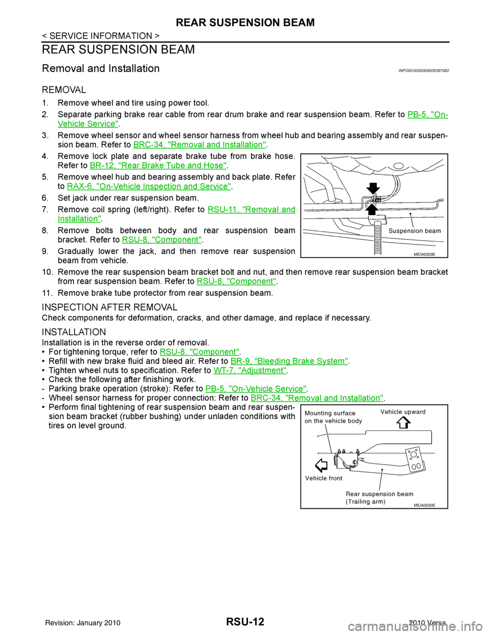
REMOVAL
1. Remove wheel and tire using power tool.
2. Separate parking brake rear cable from rear drum brake and rear suspension beam. Refer to PB-5, "
On-
Vehicle Service".
3. Remove wheel sensor and wheel sensor harness from wheel hub and bearing assembly and rear suspen-
sion beam. Refer to BRC-34, "
Removal and Installation".
4. Remove lock plate and separate brake tube from brake hose. Refer to BR-12, "
Rear Brake Tube and Hose".
5. Remove wheel hub and bearing assembly and back plate. Refer to RAX-6, "
On-Vehicle Inspection and Service".
6. Set jack under rear suspension beam.
7. Remove coil spring (left/right). Refer to RSU-11, "
Removal and
Installation".
8. Remove bolts between body and rear suspension beam bracket. Refer to RSU-8, "
Component".
9. Gradually lower the jack, and then remove rear suspension beam from vehicle.
10. Remove the rear suspension beam bracket bolt and nut, and then remove rear suspension beam bracket
from rear suspension beam. Refer to RSU-8, "
Component".
11. Remove brake tube protector from rear suspension beam.
INSPECTION AFTER REMOVAL
Check components for deformation, cracks, and other damage, and replace if necessary.
INSTALLATION
Installation is in the reverse order of removal.
• For tightening torque, refer to RSU-8, "
Component".
• Refill with new brake fluid and bleed air. Refer to BR-9, "
Bleeding Brake System".
• Tighten wheel nuts to specification. Refer to WT-7, "
Adjustment".
• Check the following after finishing work.
- Parking brake operation (stroke): Refer to PB-5, "
On-Vehicle Service".
- Wheel sensor harness for proper connection: Refer to BRC-34, "
Removal and Installation".
• Perform final tightening of rear suspension beam and rear suspen-
sion beam bracket (rubber bushing) under unladen conditions with
tires on level ground.
MEIA0029E
MEIA0030E
Revision: January 20102010 Versa
Page 3571 of 3745
SQUEAK AND RATTLE TROUBLE DIAGNOSESSE-5
< SERVICE INFORMATION >
C
DE
F
G H
J
K L
M A
B
SE
N
O P
SQUEAK AND RATTLE TROUBLE DIAGNOSES
Work FlowINFOID:0000000005396865
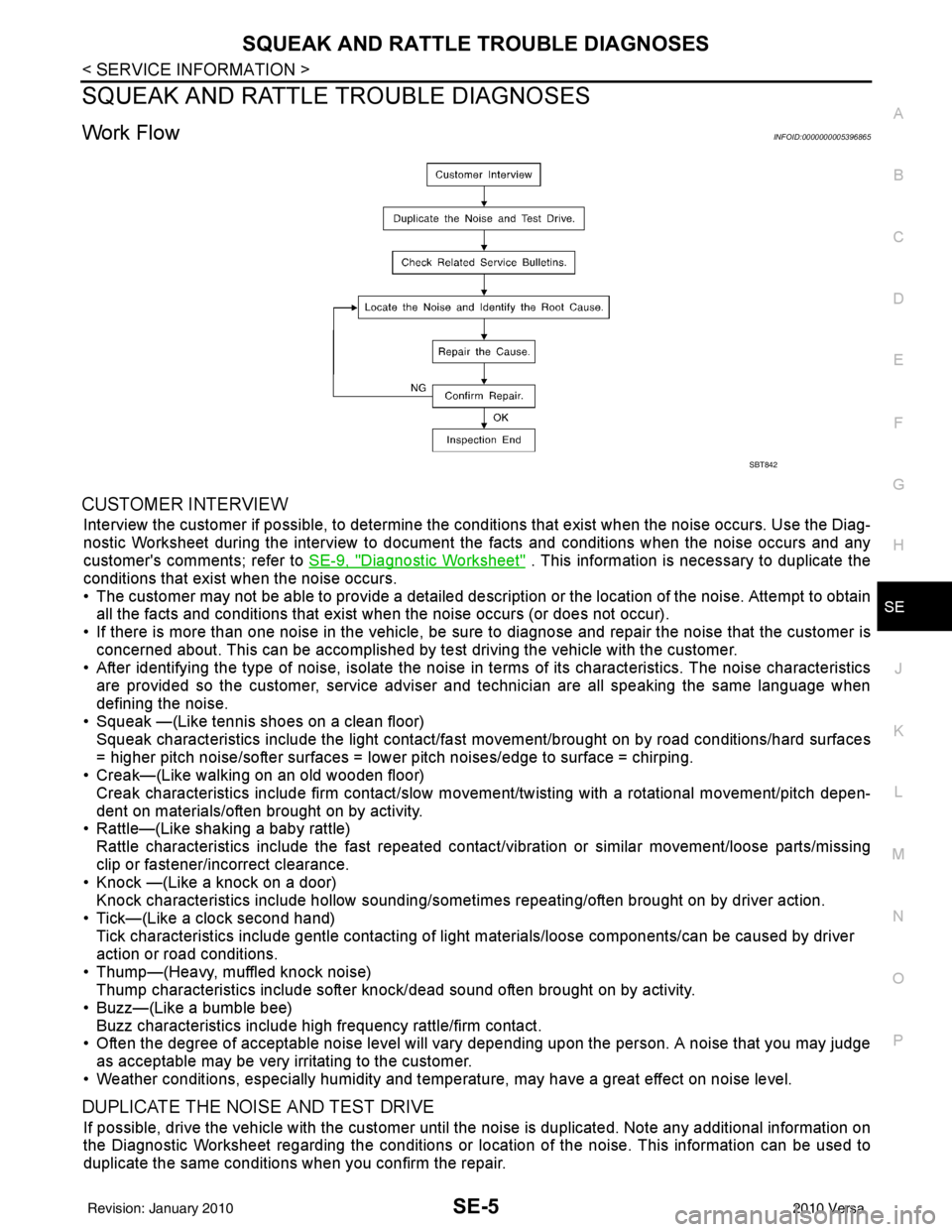
CUSTOMER INTERVIEW
Interview the customer if possible, to determine the conditions that exist when the noise occurs. Use the Diag-
nostic Worksheet during the interv iew to document the facts and conditions when the noise occurs and any
customer's comments; refer to SE-9, "
Diagnostic Worksheet" . This information is necessary to duplicate the
conditions that exist when the noise occurs.
• The customer may not be able to provide a detailed descr iption or the location of the noise. Attempt to obtain
all the facts and conditions that exist when the noise occurs (or does not occur).
• If there is more than one noise in the vehicle, be sure to diagnose and repair the noise that the customer is
concerned about. This can be accomplished by test driving the vehicle with the customer.
• After identifying the type of noise, isolate the noise in terms of its characteristics. The noise characteristics
are provided so the customer, service adviser and technician are all speaking the same language when
defining the noise.
• Squeak —(Like tennis shoes on a clean floor)
Squeak characteristics include the light contact/fast movement/brought on by road conditions/hard surfaces
= higher pitch noise/softer surfaces = lower pitch noises/edge to surface = chirping.
• Creak—(Like walking on an old wooden floor)
Creak characteristics include firm contact/slow mo vement/twisting with a rotational movement/pitch depen-
dent on materials/often brought on by activity.
• Rattle—(Like shaking a baby rattle)
Rattle characteristics include the fast repeated contac t/vibration or similar movement/loose parts/missing
clip or fastener/incorrect clearance.
• Knock —(Like a knock on a door)
Knock characteristics include hollow sounding/someti mes repeating/often brought on by driver action.
• Tick—(Like a clock second hand) Tick characteristics include gentle contacting of li ght materials/loose components/can be caused by driver
action or road conditions.
• Thump—(Heavy, muffled knock noise) Thump characteristics include softer k nock/dead sound often brought on by activity.
• Buzz—(Like a bumble bee)
Buzz characteristics include high frequency rattle/firm contact.
• Often the degree of acceptable noise level will vary depending upon the person. A noise that you may judge as acceptable may be very irritating to the customer.
• Weather conditions, especially humidity and temperature, may have a great effect on noise level.
DUPLICATE THE NOISE AND TEST DRIVE
If possible, drive the vehicle with the customer until the noise is duplicated. Note any additional information on
the Diagnostic Worksheet regarding the conditions or lo cation of the noise. This information can be used to
duplicate the same conditions when you confirm the repair.
SBT842
Revision: January 20102010 Versa