2010 NISSAN LATIO air condition
[x] Cancel search: air conditionPage 2759 of 3745
GW-42
< SERVICE INFORMATION >
POWER WINDOW SYSTEM
NG >> Repair or replace harness.
Rear Power Window Motor RH Circuit InspectionINFOID:0000000005396761
1.CHECK REAR POWER WINDOW SWITCH RH OUTPUT SIGNAL
1. Turn ignition switch OFF.
2. Disconnect rear power window motor RH.
3. Turn ignition switch ON.
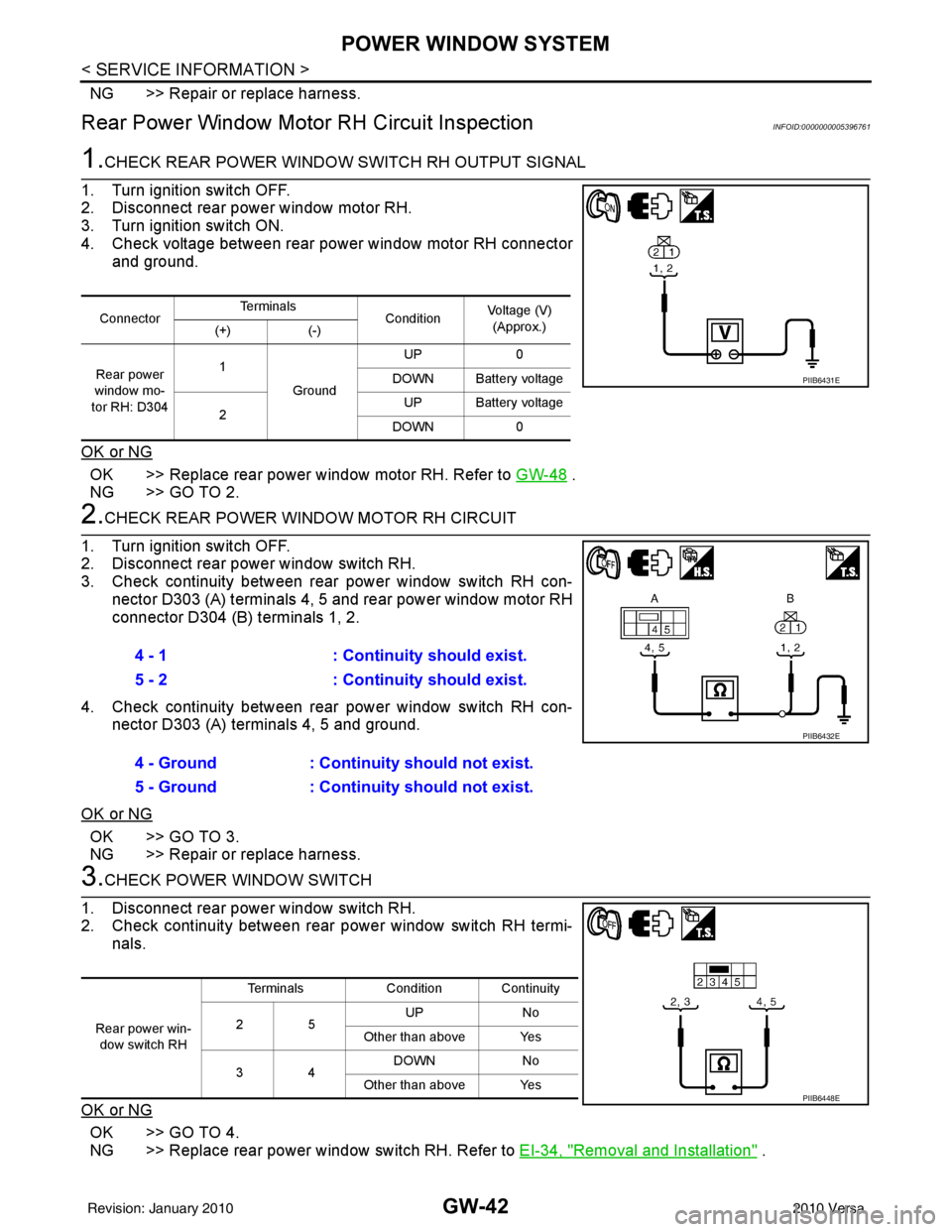
4. Check voltage between rear power window motor RH connector and ground.
OK or NG
OK >> Replace rear power window motor RH. Refer to GW-48 .
NG >> GO TO 2.
2.CHECK REAR POWER WINDOW MOTOR RH CIRCUIT
1. Turn ignition switch OFF.
2. Disconnect rear power window switch RH.
3. Check continuity between rear power window switch RH con- nector D303 (A) terminals 4, 5 and rear power window motor RH
connector D304 (B) terminals 1, 2.
4. Check continuity between rear power window switch RH con- nector D303 (A) terminals 4, 5 and ground.
OK or NG
OK >> GO TO 3.
NG >> Repair or replace harness.
3.CHECK POWER WINDOW SWITCH
1. Disconnect rear power window switch RH.
2. Check continuity between rear power window switch RH termi- nals.
OK or NG
OK >> GO TO 4.
NG >> Replace rear power window switch RH. Refer to EI-34, "
Removal and Installation" .
ConnectorTe r m i n a l s
ConditionVoltage (V)
(Approx.)
(+) (-)
Rear power
window mo-
tor RH: D304 1
Ground UP
0
DOWN Battery voltage
2 UP Battery voltage
DOWN 0
PIIB6431E
4 - 1 : Continuity should exist.
5 - 2 : Continuity should exist.
4 - Ground : Continuity should not exist.
5 - Ground : Continuity should not exist.
PIIB6432E
Rear power win-
dow switch RH Terminals
Condition Continuity
25 UP
No
Other than above Yes
34 DOWN
No
Other than above Yes
PIIB6448E
Revision: January 20102010 Versa
Page 2772 of 3745

REAR WINDOW DEFOGGERGW-55
< SERVICE INFORMATION >
C
DE
F
G H
J
K L
M A
B
GW
N
O P
Terminal and Reference Value for BCMINFOID:0000000005396772
Refer to BCS-12, "Terminal and Reference Value for BCM" .
Terminal and Reference Value for IPDM E/RINFOID:0000000005396773
Refer to PG-25, "Terminal and Reference Value for IPDM E/R" .
Work FlowINFOID:0000000005396774
1. Check the symptom and customer's requests.
2. Understand the outline of system. Refer to GW-51, "
System Description" .
3. According to the trouble diagnosis chart, repair or replace the cause of the malfunction. Refer to GW-55,
"Trouble Diagnosis Symptom Chart" .
4. Does rear window defogger operate normally? YES: GO TO 5, NO: GO TO 3.
5. Inspection End.
CONSULT-III Function (BCM)INFOID:0000000005396775
CONSULT-III can display each diagnostic item using the diagnostic test modes shown following.
DATA MONITOR
Display Item List
ACTIVE TEST
Display Item List
Trouble Diagnosis Symptom ChartINFOID:0000000005396776
Make sure other systems using the signal of the following systems operate normally.
BCM diagnostic
test item Diagnostic mode
Content
Inspection by part WORK SUPPORT
Supports inspections and adjustments. Commands are transmitted to the BCM for
setting the status suitable for required operation, input/output signals are received
from the BCM and received data is displayed.
DATA MONITOR Displays BCM input/output data in real time. ACTIVE TEST Operation of electrical loads can be checked by sending drive signal to them.
SELF DIAGNOSTIC RE- SULT Displays BCM self-diagnosis results.
CAN DIAG SUPPORT MNTR The results of transmit/receive diagnosis of CAN communication can be read.
ECU IDENTIFICATION BCM part number can be read. CONFIGURATION Performs BCM configuration read/write functions.
Monitor item “Operation” Content
REAR DEF SW “ON/OFF” Indicates (ON/OFF) condition of the rear window defogger switch.
IGN ON SW “ON/OFF” Indicates (ON/OFF) condition of the ignition switch signal.
Test item Content
REAR WINDOW DEFOGGER Gives a drive signal to the rear window defogger to activate it.
Revision: January 20102010 Versa
Page 2773 of 3745
GW-56
< SERVICE INFORMATION >
REAR WINDOW DEFOGGER
BCM Power Supply and Ground Circuit Inspection
INFOID:0000000005396777
Refer to BCS-16, "BCM Power Supply and Ground Circuit Inspection" .
Rear Window Defogger Swit ch Circuit InspectionINFOID:0000000005396778
1.CHECK REAR WINDOW DEFOGGER SWITCH OPERATION
With CONSULT-III
Check (“REAR DEF SW”, “IGN ON SW”) in DATA MONITOR mode with CONSULT-III.
Without CONSULT-III
1. Turn ignition switch ON.
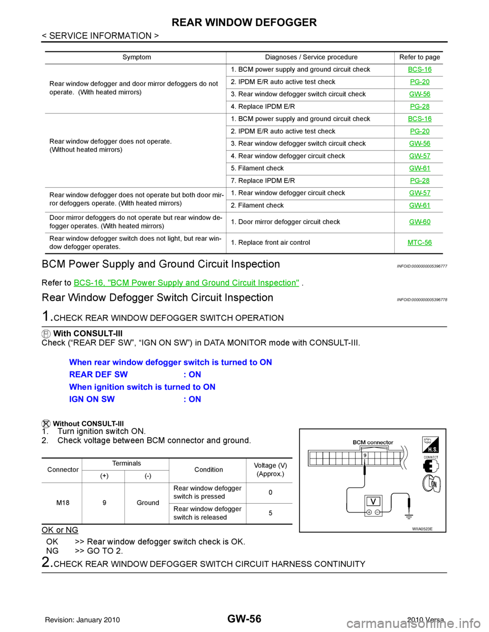
2. Check voltage between BCM connector and ground.
OK or NG
OK >> Rear window defogger switch check is OK.
NG >> GO TO 2.
2.CHECK REAR WINDOW DEFOGGER SWITCH CIRCUIT HARNESS CONTINUITY
Symptom Diagnoses / Service procedureRefer to page
Rear window defogger and door mirror defoggers do not
operate. (With heated mirrors) 1. BCM power supply and ground circuit check
BCS-16
2. IPDM E/R auto active test check PG-20
3. Rear window defogger switch circuit checkGW-56
4. Replace IPDM E/R PG-28
Rear window defogger does not operate.
(Without heated mirrors) 1. BCM power supply and ground circuit check
BCS-16
2. IPDM E/R auto active test check PG-20
3. Rear window defogger switch circuit checkGW-56
4. Rear window defogger circuit checkGW-57
5. Filament checkGW-61
7. Replace IPDM E/R PG-28
Rear window defogger does not operate but both door mir-
ror defoggers operate. (With heated mirrors) 1. Rear window defogger circuit check
GW-57
2. Filament checkGW-61
Door mirror defoggers do not operate but rear window de-
fogger operates. (With heated mirrors) 1. Door mirror defogger circuit check
GW-60
Rear window defogger switch does not light, but rear win-
dow defogger operates. 1. Replace front air control
MTC-56
When rear window defogger switch is turned to ON
REAR DEF SW: ON
When ignition switch is turned to ON
IGN ON SW : ON
ConnectorTe r m i n a l s
ConditionVoltage (V)
(Approx.)
(+) (-)
M18 9 Ground Rear window defogger
switch is pressed
0
Rear window defogger
switch is released 5
WIIA0523E
Revision: January 20102010 Versa
Page 2774 of 3745
REAR WINDOW DEFOGGERGW-57
< SERVICE INFORMATION >
C
DE
F
G H
J
K L
M A
B
GW
N
O P
1. Turn ignition switch OFF.
2. Disconnect BCM and front air control.
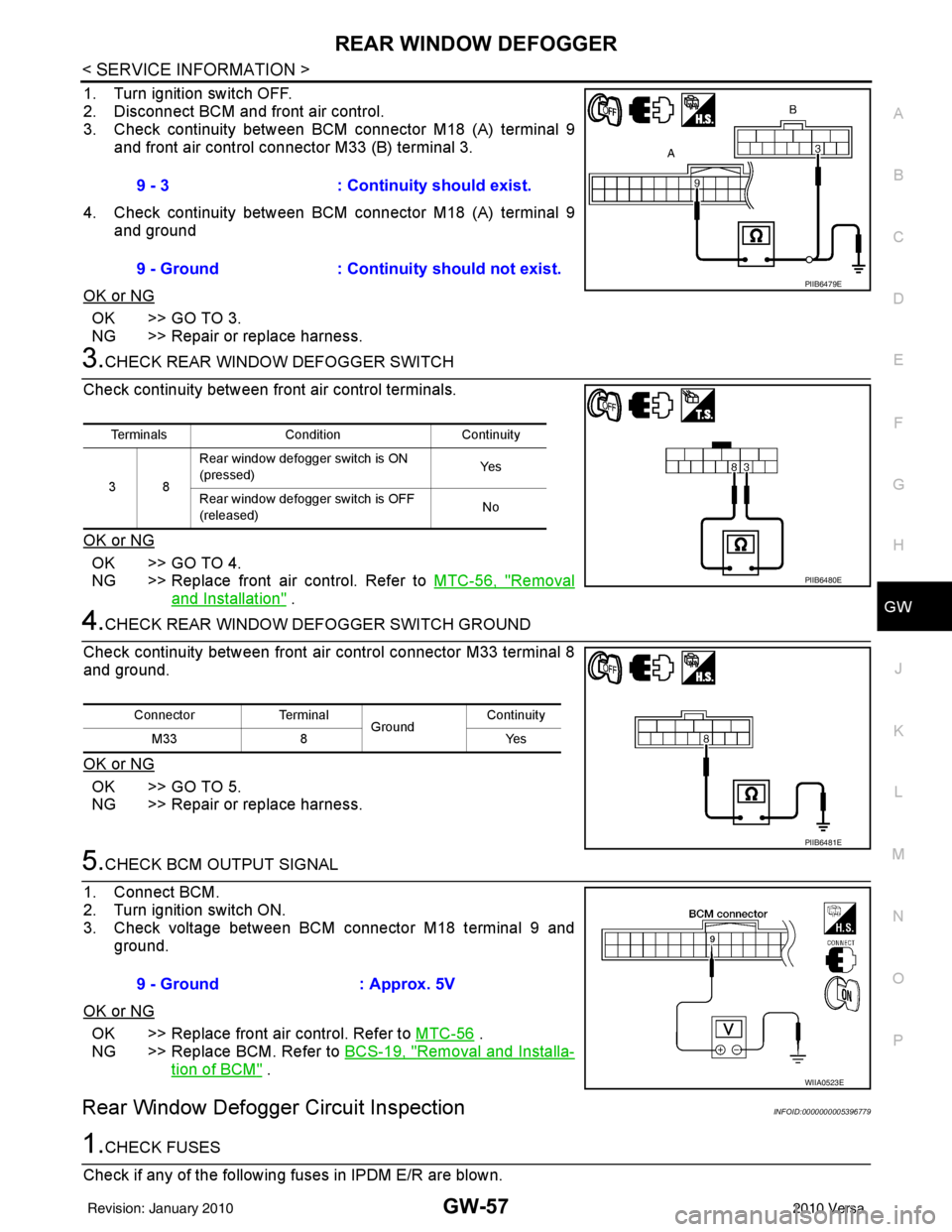
3. Check continuity between BCM connector M18 (A) terminal 9 and front air control connector M33 (B) terminal 3.
4. Check continuity between BCM connector M18 (A) terminal 9 and ground
OK or NG
OK >> GO TO 3.
NG >> Repair or replace harness.
3.CHECK REAR WINDOW DEFOGGER SWITCH
Check continuity between fr ont air control terminals.
OK or NG
OK >> GO TO 4.
NG >> Replace front air control. Refer to MTC-56, "
Removal
and Installation" .
4.CHECK REAR WINDOW DEFOGGER SWITCH GROUND
Check continuity between front air control connector M33 terminal 8
and ground.
OK or NG
OK >> GO TO 5.
NG >> Repair or replace harness.
5.CHECK BCM OUTPUT SIGNAL
1. Connect BCM.
2. Turn ignition switch ON.
3. Check voltage between BCM connector M18 terminal 9 and ground.
OK or NG
OK >> Replace front air control. Refer to MTC-56 .
NG >> Replace BCM. Refer to BCS-19, "
Removal and Installa-
tion of BCM" .
Rear Window Defogger Circuit InspectionINFOID:0000000005396779
1.CHECK FUSES
Check if any of the following fuses in IPDM E/R are blown. 9 - 3
: Continuity should exist.
9 - Ground : Continuity should not exist.
PIIB6479E
Terminals Condition Continuity
38 Rear window defogger switch is ON
(pressed)
Ye s
Rear window defogger switch is OFF
(released) No
PIIB6480E
Connector
Terminal
Ground Continuity
8Y es
M33
PIIB6481E
9 - Ground : Approx. 5V
WIIA0523E
Revision: January 20102010 Versa
Page 2775 of 3745
GW-58
< SERVICE INFORMATION >
REAR WINDOW DEFOGGER
OK or NG
OK >> GO TO 2.
NG >> If fuse is blown, be sure to eliminate cause of malfunction before installing new fuse.
2.CHECK REAR WINDOW DEFOGGER POWER SUPPLY CIRCUIT
1. Turn ignition switch OFF.
2. Disconnect rear window defogger.
3. Turn ignition switch ON.
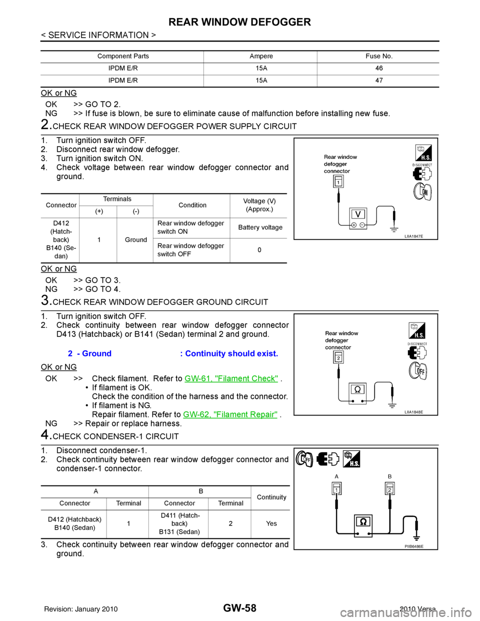
4. Check voltage between rear window defogger connector and ground.
OK or NG
OK >> GO TO 3.
NG >> GO TO 4.
3.CHECK REAR WINDOW DEFOGGER GROUND CIRCUIT
1. Turn ignition switch OFF.
2. Check continuity between rear window defogger connector D413 (Hatchback) or B141 (Sedan) terminal 2 and ground.
OK or NG
OK >> Check filament. Refer to GW-61, "Filament Check" .
• If filament is OK.
Check the condition of the harness and the connector.
• If filament is NG. Repair filament. Refer to GW-62, "
Filament Repair" .
NG >> Repair or replace harness.
4.CHECK CONDENSER-1 CIRCUIT
1. Disconnect condenser-1.
2. Check continuity between rear window defogger connector and condenser-1 connector.
3. Check continuity between rear window defogger connector and ground.
Component Parts AmpereFuse No.
IPDM E/R 15A46
IPDM E/R 15A47
ConnectorTe r m i n a l s
ConditionVoltage (V)
(Approx.)
(+) (-)
D412
(Hatch- back)
B140 (Se-
dan) 1Ground Rear window defogger
switch ON
Battery voltage
Rear window defogger
switch OFF 0
LIIA1847E
2 - Ground
: Continuity should exist.
LIIA1848E
AB
Continuity
Connector Terminal Connector Terminal
D412 (Hatchback) B140 (Sedan) 1 D411 (Hatch-
back)
B131 (Sedan) 2Y
es
PIIB6486E
Revision: January 20102010 Versa
Page 2776 of 3745
REAR WINDOW DEFOGGERGW-59
< SERVICE INFORMATION >
C
DE
F
G H
J
K L
M A
B
GW
N
O P
OK or NG
OK >> GO TO 5.
NG >> Repair or replace harness.
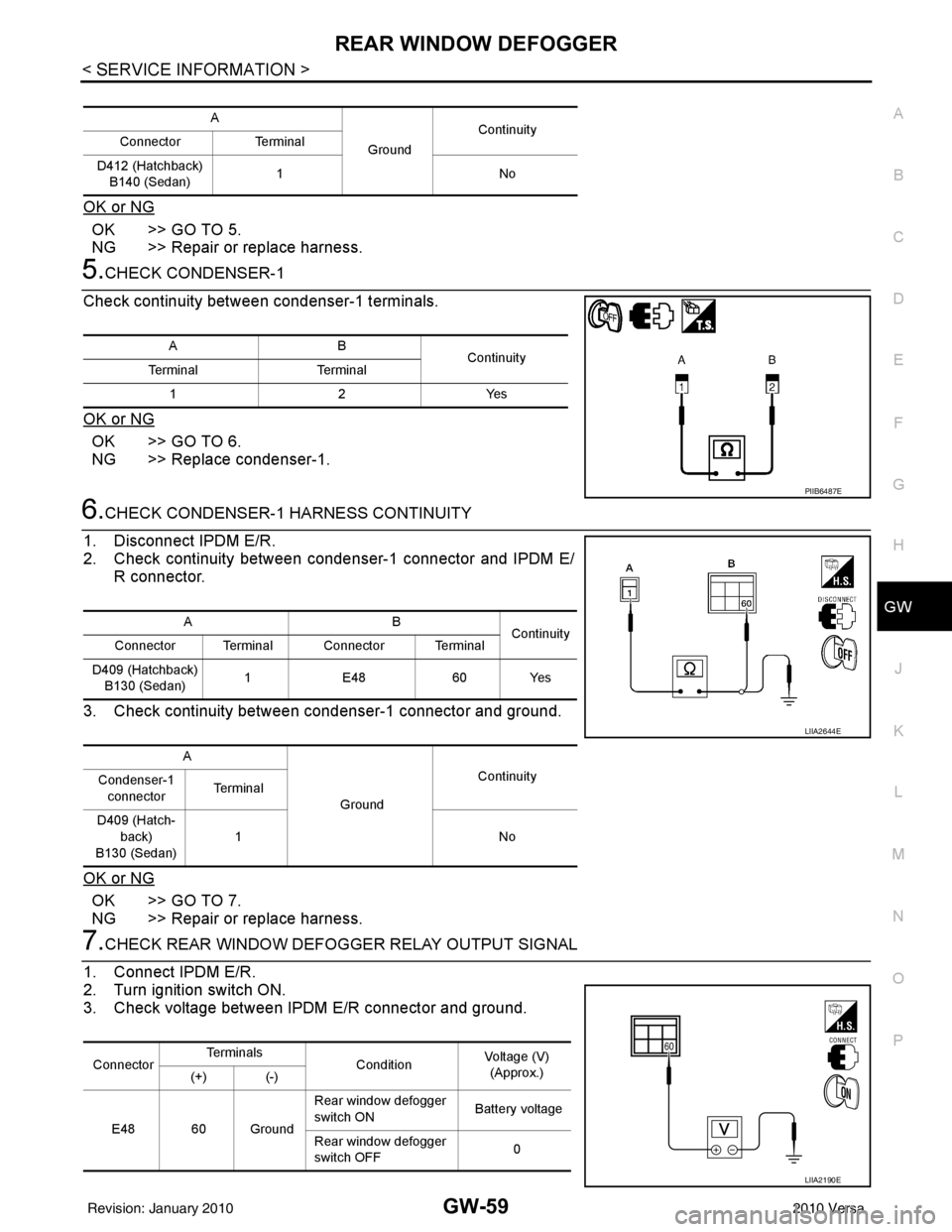
5.CHECK CONDENSER-1
Check continuity between condenser-1 terminals.
OK or NG
OK >> GO TO 6.
NG >> Replace condenser-1.
6.CHECK CONDENSER-1 HARNESS CONTINUITY
1. Disconnect IPDM E/R.
2. Check continuity between condenser-1 connector and IPDM E/ R connector.
3. Check continuity between condenser-1 connector and ground.
OK or NG
OK >> GO TO 7.
NG >> Repair or replace harness.
7.CHECK REAR WINDOW DEFOGGER RELAY OUTPUT SIGNAL
1. Connect IPDM E/R.
2. Turn ignition switch ON.
3. Check voltage between IPDM E/R connector and ground.
A
GroundContinuity
Connector Terminal
D412 (Hatchback) B140 (Sedan) 1N
o
AB
Continuity
Te r m i n a l Te r m i n a l
12Y es
PIIB6487E
AB
Continuity
Connector Terminal Connector Terminal
D409 (Hatchback) B130 (Sedan) 1
E48 60 Yes
A GroundContinuity
Condenser-1
connector Te r m i n a l
D409 (Hatch- back)
B130 (Sedan) 1N
o
LIIA2644E
ConnectorTe r m i n a l s
ConditionVoltage (V)
(Approx.)
(+) (-)
E48 60 Ground Rear window defogger
switch ON
Battery voltage
Rear window defogger
switch OFF 0
LIIA2190E
Revision: January 20102010 Versa
Page 2777 of 3745
GW-60
< SERVICE INFORMATION >
REAR WINDOW DEFOGGER
OK or NG
OK >> Check condition of harness and connector.
NG >> Replace IPDM E/R. Refer to PG-28, "
Removal and Installation of IPDM E/R" .
Door Mirror Defogger Circuit InspectionINFOID:0000000005396780
1.CHECK FUSE
Check if the following fuse in the fuse block (J/B) is blown.
OK or NG
OK >> GO TO 2.
NG >> If fuse is blown, be sure to eliminate cause of malfunction before installing new fuse.
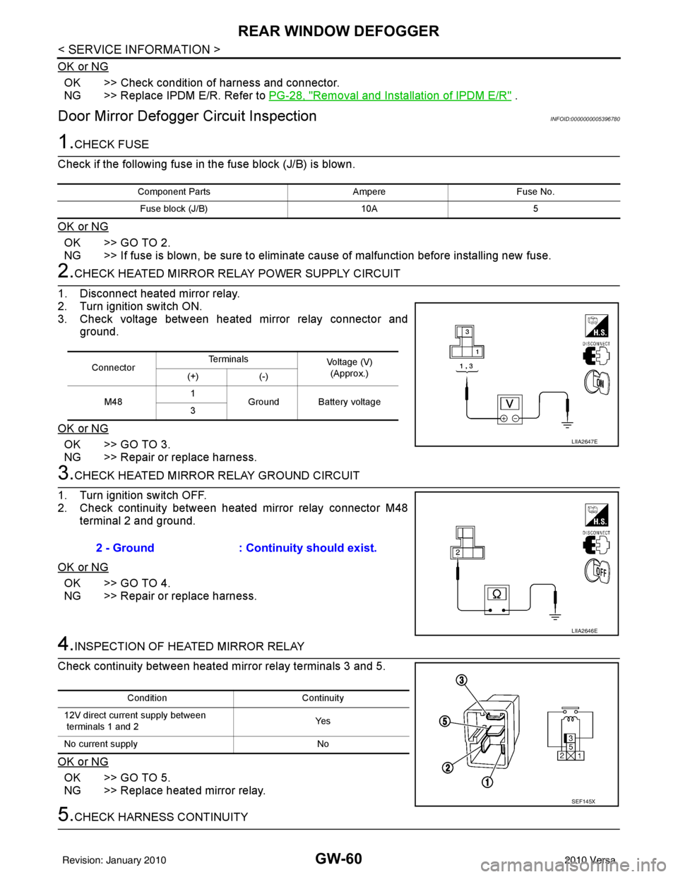
2.CHECK HEATED MIRROR RELAY POWER SUPPLY CIRCUIT
1. Disconnect heated mirror relay.
2. Turn ignition switch ON.
3. Check voltage between heated mirror relay connector and ground.
OK or NG
OK >> GO TO 3.
NG >> Repair or replace harness.
3.CHECK HEATED MIRROR RELAY GROUND CIRCUIT
1. Turn ignition switch OFF.
2. Check continuity between heated mirror relay connector M48 terminal 2 and ground.
OK or NG
OK >> GO TO 4.
NG >> Repair or replace harness.
4.INSPECTION OF HEATED MIRROR RELAY
Check continuity between heated mirror relay terminals 3 and 5.
OK or NG
OK >> GO TO 5.
NG >> Replace heated mirror relay.
5.CHECK HARNESS CONTINUITY
Component Parts AmpereFuse No.
Fuse block (J/B) 10A5
ConnectorTe r m i n a l s
Voltage (V)
(Approx.)
(+) (-)
M48 1
Ground Battery voltage
3
LIIA2647E
2 - Ground : Continuity should exist.
LIIA2646E
Condition Continuity
12V direct current supply between
terminals 1 and 2 Ye s
No current supply No
SEF145X
Revision: January 20102010 Versa
Page 2789 of 3745
SQUEAK AND RATTLE TROUBLE DIAGNOSESIP-5
< SYMPTOM DIAGNOSIS >
C
DE
F
G H
J
K L
M A
B
IP
N
O P
SYMPTOM DIAGNOSIS
SQUEAK AND RATTLE TROUBLE DIAGNOSES
Work FlowINFOID:0000000005396853
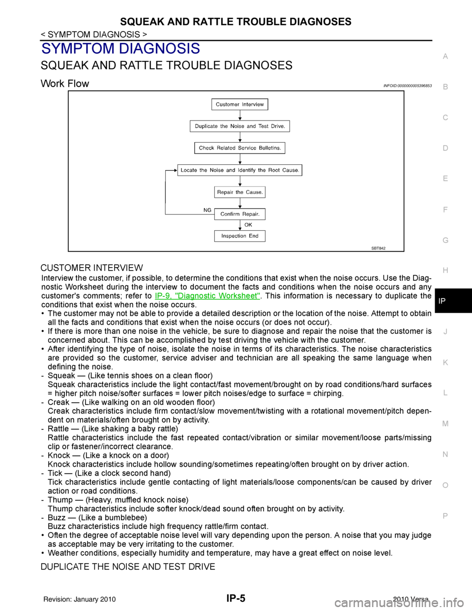
CUSTOMER INTERVIEW
Interview the customer, if possible, to determine the c onditions that exist when the noise occurs. Use the Diag-
nostic Worksheet during the interv iew to document the facts and conditions when the noise occurs and any
customer's comments; refer to IP-9, "
Diagnostic Worksheet". This information is necessary to duplicate the
conditions that exist when the noise occurs.
• The customer may not be able to provide a detailed descr iption or the location of the noise. Attempt to obtain
all the facts and conditions that exist when the noise occurs (or does not occur).
• If there is more than one noise in the vehicle, be sure to diagnose and repair the noise that the customer is
concerned about. This can be accomplished by te st driving the vehicle with the customer.
• After identifying the type of noise, isolate the noise in terms of its characteristics. The noise characteristics are provided so the customer, service adviser and technician are all speaking the same language when
defining the noise.
- Squeak — (Like tennis shoes on a clean floor) Squeak characteristics include the light contact/fast movement/brought on by road conditions/hard surfaces
= higher pitch noise/softer surfaces = lower pitch noises/edge to surface = chirping.
- Creak — (Like walking on an old wooden floor) Creak characteristics include firm contact/slow mo vement/twisting with a rotational movement/pitch depen-
dent on materials/often brought on by activity.
- Rattle — (Like shaking a baby rattle) Rattle characteristics include the fast repeated contac t/vibration or similar movement/loose parts/missing
clip or fastener/incorrect clearance.
- Knock — (Like a knock on a door) Knock characteristics include hollow sounding/someti mes repeating/often brought on by driver action.
- Tick — (Like a clock second hand) Tick characteristics include gentle contacting of li ght materials/loose components/can be caused by driver
action or road conditions.
- Thump — (Heavy, muffled knock noise)
Thump characteristics include softer k nock/dead sound often brought on by activity.
- Buzz — (Like a bumblebee) Buzz characteristics include high frequency rattle/firm contact.
• Often the degree of acceptable noise level will vary depending upon the person. A noise that you may judge as acceptable may be very irritating to the customer.
• Weather conditions, especially humidity and temperature, may have a great effect on noise level.
DUPLICATE THE NOISE AND TEST DRIVE
SBT842
Revision: January 20102010 Versa