2010 NISSAN LATIO checking oil
[x] Cancel search: checking oilPage 2382 of 3745
COMPRESSION PRESSUREEM-23
< ON-VEHICLE MAINTENANCE > [HR16DE]
C
D
E
F
G H
I
J
K L
M A
EM
NP
O
COMPRESSION PRESSURE
InspectionINFOID:0000000005398044
1. Warm up engine thoroughly. Then, stop it.
2. Release fuel pressure. Refer to
EC-496, "
Inspection".
3. Remove ignition coil and spark plug from each cylinder. Refer to EM-46, "
Exploded View".
4. Connect an engine tachometer (not required in use of CONSULT-III).
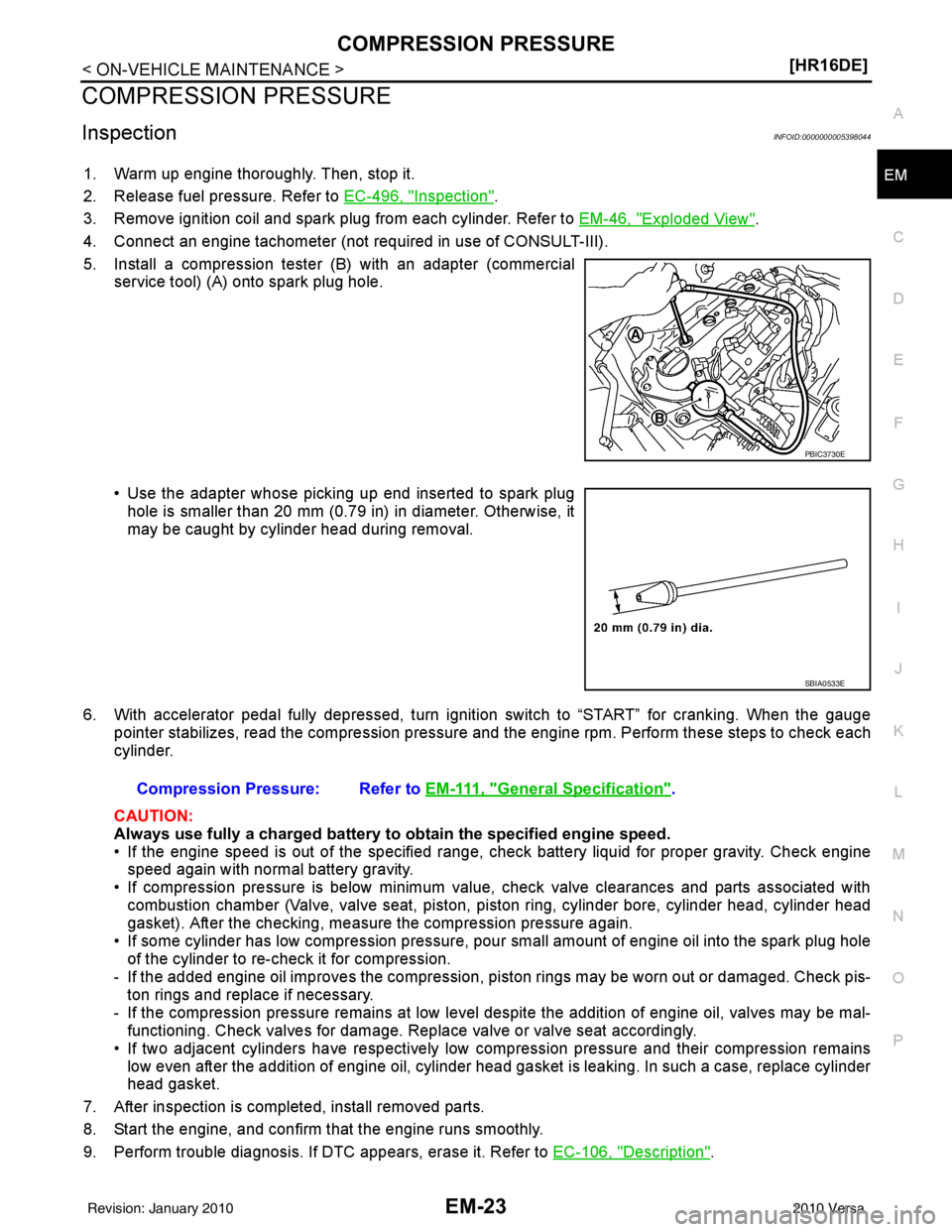
5. Install a compression tester (B) with an adapter (commercial service tool) (A) onto spark plug hole.
• Use the adapter whose picking up end inserted to spark plughole is smaller than 20 mm (0.79 in) in diameter. Otherwise, it
may be caught by cylinder head during removal.
6. With accelerator pedal fully depressed, turn ignition switch to “START” for cranking. When the gauge pointer stabilizes, read the compression pressure and the engine rpm. Perform these steps to check each
cylinder.
CAUTION:
Always use fully a charged battery to obtain the specified engine speed.
• If the engine speed is out of the specified range, check battery liquid for proper gravity. Check engine speed again with normal battery gravity.
• If compression pressure is below minimum value, check valve clearances and parts associated with combustion chamber (Valve, valve seat, piston, pi ston ring, cylinder bore, cylinder head, cylinder head
gasket). After the checking, measure the compression pressure again.
• If some cylinder has low compression pressure, pour small amount of engine oil into the spark plug hole
of the cylinder to re-check it for compression.
- If the added engine oil improves the compression, piston rings may be worn out or damaged. Check pis-
ton rings and replace if necessary.
- If the compression pressure remains at low level despite the addition of engine oil, valves may be mal- functioning. Check valves for damage. Replace valve or valve seat accordingly.
• If two adjacent cylinders have respectively low compression pressure and their compression remains low even after the addition of engine oil, cylinder head gasket is leaking. In such a case, replace cylinder
head gasket.
7. After inspection is completed, install removed parts.
8. Start the engine, and confirm that the engine runs smoothly.
9. Perform trouble diagnosis. If DTC appears, erase it. Refer to EC-106, "
Description".
PBIC3730E
SBIA0533E
Compression Pressure: Refer to E M - 111 , "General Specification".
Revision: January 20102010 Versa
Page 2396 of 3745
FUEL INJECTOR AND FUEL TUBEEM-37
< ON-VEHICLE REPAIR > [HR16DE]
C
D
E
F
G H
I
J
K L
M A
EM
NP
O
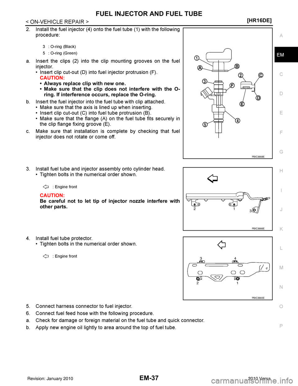
2. Install the fuel injector (4) onto the fuel tube (1) with the following
procedure:
a. Insert the clips (2) into the clip mounting grooves on the fuel injector.
• Insert clip cut-out (D) into fuel injector protrusion (F).
CAUTION:
• Always replace clip with new one.
• Make sure that the clip do es not interfere with the O-
ring. If interference occurs, replace the O-ring.
b. Insert the fuel injector into the fuel tube with clip attached. • Make sure that the axis is lined up when inserting.
• Insert clip cut-out (C) into fuel tube protrusion (B).
• Make sure that the flange (A) on the fuel tube fits securely inthe clip flange fixing groove (E).
c. Make sure that installation is complete by checking that fuel injector does not rotate or come off.
3. Install fuel tube and injector assembly onto cylinder head. • Tighten bolts in the numerical order shown.
CAUTION:
Be careful not to let tip of injector nozzle interfere with
other parts.
4. Install fuel tube protector. • Tighten bolts in the numerical order shown.
5. Connect harness connector to fuel injector.
6. Connect fuel feed hose with the following procedure.
a. Check for damage or foreign material on the fuel tube and quick connector.
b. Apply new engine oil lightly to area around the top of fuel tube.
3 : O-ring (Black)
5 : O-ring (Green)
PBIC3668E
: Engine front
PBIC3666E
: Engine front
PBIC3665E
Revision: January 20102010 Versa
Page 2406 of 3745
IGNITION COIL, SPARK PLUG AND ROCKER COVER
EM-47
< ON-VEHICLE REPAIR > [HR16DE]
C
D
E
F
G H
I
J
K L
M A
EM
NP
O
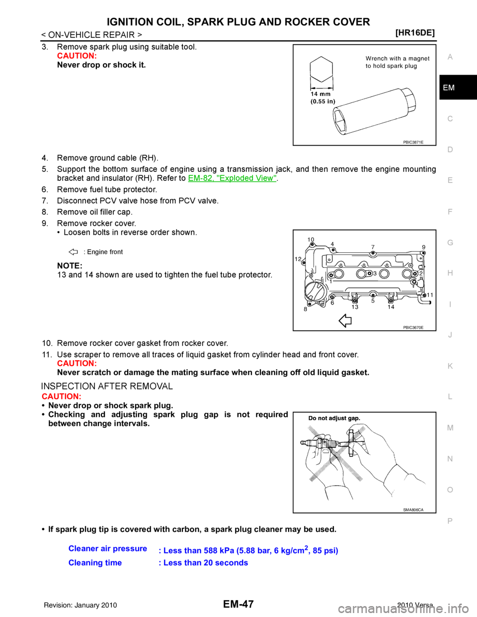
3. Remove spark plug using suitable tool.
CAUTION:
Never drop or shock it.
4. Remove ground cable (RH).
5. Support the bottom surface of engine using a trans mission jack, and then remove the engine mounting
bracket and insulator (RH). Refer to EM-82, "
Exploded View".
6. Remove fuel tube protector.
7. Disconnect PCV valve hose from PCV valve.
8. Remove oil filler cap.
9. Remove rocker cover. • Loosen bolts in reverse order shown.
NOTE:
13 and 14 shown are used to tighten the fuel tube protector.
10. Remove rocker cover gasket from rocker cover.
11. Use scraper to remove all traces of liquid gasket from cylinder head and front cover.
CAUTION:
Never scratch or damage the mating surface when cleaning off old liquid gasket.
INSPECTION AFTER REMOVAL
CAUTION:
• Never drop or shock spark plug.
• Checking and adjusting spar k plug gap is not required
between change intervals.
• If spark plug tip is covered with carbon, a spark plug cleaner may be used.
PBIC3871E
: Engine front
PBIC3670E
SMA806CA
Cleaner air pressure
: Less than 588 kPa (5.88 bar, 6 kg/cm2, 85 psi)
Cleaning time : Less than 20 seconds
Revision: January 20102010 Versa
Page 2427 of 3745
EM-68
< ON-VEHICLE REPAIR >[HR16DE]
CAMSHAFT
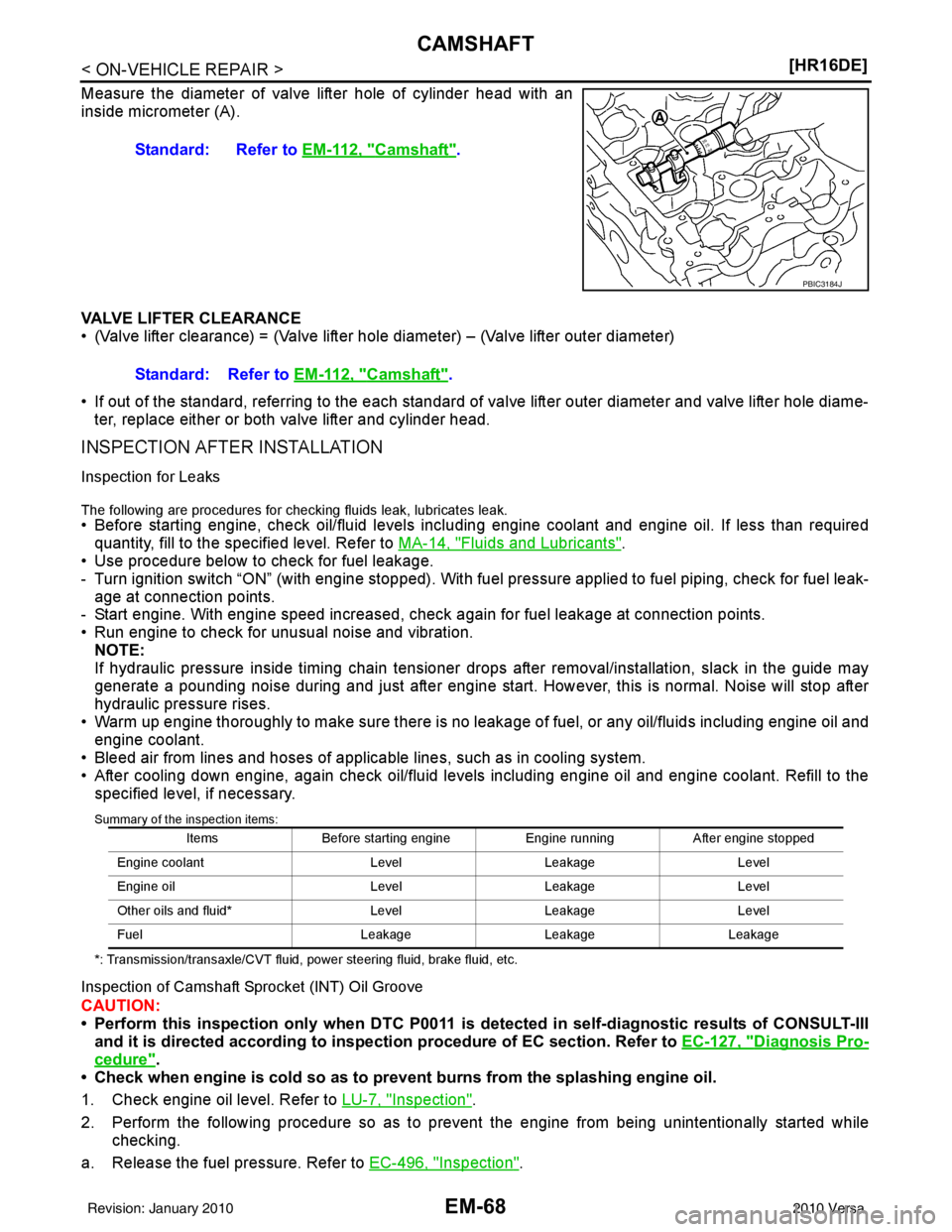
Measure the diameter of valve lifter hole of cylinder head with an
inside micrometer (A).
VALVE LIFTER CLEARANCE
• (Valve lifter clearance) = (Valve lifter hole diameter) – (Valve lifter outer diameter)
• If out of the standard, referring to the each standard of va
lve lifter outer diameter and valve lifter hole diame-
ter, replace either or both valve lifter and cylinder head.
INSPECTION AFTER INSTALLATION
Inspection for Leaks
The following are procedures for checking fluids leak, lubricates leak.
• Before starting engine, check oil/fluid levels incl uding engine coolant and engine oil. If less than required
quantity, fill to the specified level. Refer to MA-14, "
Fluids and Lubricants".
• Use procedure below to check for fuel leakage.
- Turn ignition switch “ON” (with engine stopped). With fuel pressure applied to fuel piping, check for fuel leak-
age at connection points.
- Start engine. With engine speed increased, che ck again for fuel leakage at connection points.
• Run engine to check for unusual noise and vibration. NOTE:
If hydraulic pressure inside timing chain tensioner drops after removal/installation, slack in the guide may
generate a pounding noise during and just after engine start. However, this is normal. Noise will stop after
hydraulic pressure rises.
• Warm up engine thoroughly to make sure there is no leakage of fuel, or any oil/fluids including engine oil and
engine coolant.
• Bleed air from lines and hoses of applicable lines, such as in cooling system.
• After cooling down engine, again check oil/fluid levels including engine oil and engine coolant. Refill to the specified level, if necessary.
Summary of the inspection items:
*: Transmission/transaxle/CVT fluid, power steering fluid, brake fluid, etc.
Inspection of Camshaft Sprocket (INT) Oil Groove
CAUTION:
• Perform this inspection only when DTC P0011 is de tected in self-diagnostic results of CONSULT-III
and it is directed according to inspect ion procedure of EC section. Refer to EC-127, "
Diagnosis Pro-
cedure".
• Check when engine is cold so as to pr event burns from the splashing engine oil.
1. Check engine oil level. Refer to LU-7, "
Inspection".
2. Perform the following procedure so as to prevent the engine from being unintentionally started while
checking.
a. Release the fuel pressure. Refer to EC-496, "
Inspection".
Standard: Refer to
EM-112, "
Camshaft".
PBIC3184J
Standard: Refer to EM-112, "Camshaft".
Items Before starting engine Engine runningAfter engine stopped
Engine coolant LevelLeakage Level
Engine oil LevelLeakage Level
Other oils and fluid* LevelLeakage Level
Fuel LeakageLeakageLeakage
Revision: January 20102010 Versa
Page 2428 of 3745
CAMSHAFTEM-69
< ON-VEHICLE REPAIR > [HR16DE]
C
D
E
F
G H
I
J
K L
M A
EM
NP
O
b. Remove intake manifold. Refer to EM-28, "Exploded View".
c. Disconnect ignition coil and inject or harness connectors. Refer to EM-46, "
Exploded View".
3. Remove intake valve timing control solenoid valve. Refer to EM-49, "
Exploded View".
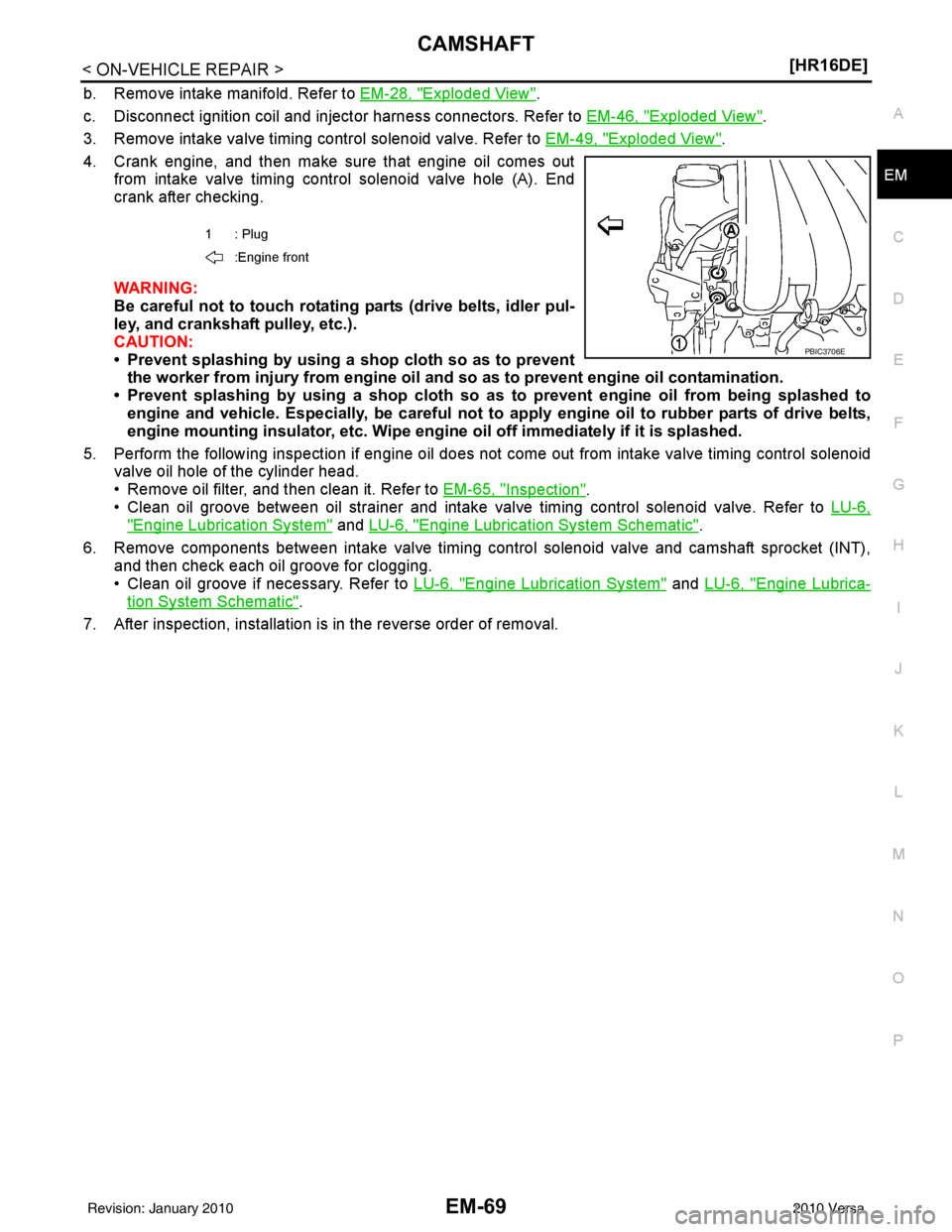
4. Crank engine, and then make sure that engine oil comes out from intake valve timing control solenoid valve hole (A). End
crank after checking.
WARNING:
Be careful not to touch rotating parts (drive belts, idler pul-
ley, and crankshaft pulley, etc.).
CAUTION:
• Prevent splashing by using a shop cloth so as to prevent the worker from injury from engine oil an d so as to prevent engine oil contamination.
• Prevent splashing by using a shop cloth so as to prevent engine oil from being splashed to
engine and vehicle. Especially, be careful not to apply engine oil to rubber parts of drive belts,
engine mounting insulator, etc. Wipe engine oil off immediately if it is splashed.
5. Perform the following inspection if engine oil does not come out from intake valve timing control solenoid
valve oil hole of the cylinder head.
• Remove oil filter, and then clean it. Refer to EM-65, "
Inspection".
• Clean oil groove between oil strainer and intake valve timing control solenoid valve. Refer to LU-6,
"Engine Lubrication System" and LU-6, "Engine Lubrication System Schematic".
6. Remove components between intake valve timing control solenoid valve and camshaft sprocket (INT), and then check each oil groove for clogging.
• Clean oil groove if necessary. Refer to LU-6, "
Engine Lubrication System" and LU-6, "Engine Lubrica-
tion System Schematic".
7. After inspection, installation is in the reverse order of removal.
1: Plug
:Engine front
PBIC3706E
Revision: January 20102010 Versa
Page 2433 of 3745
EM-74
< ON-VEHICLE REPAIR >[HR16DE]
CYLINDER HEAD
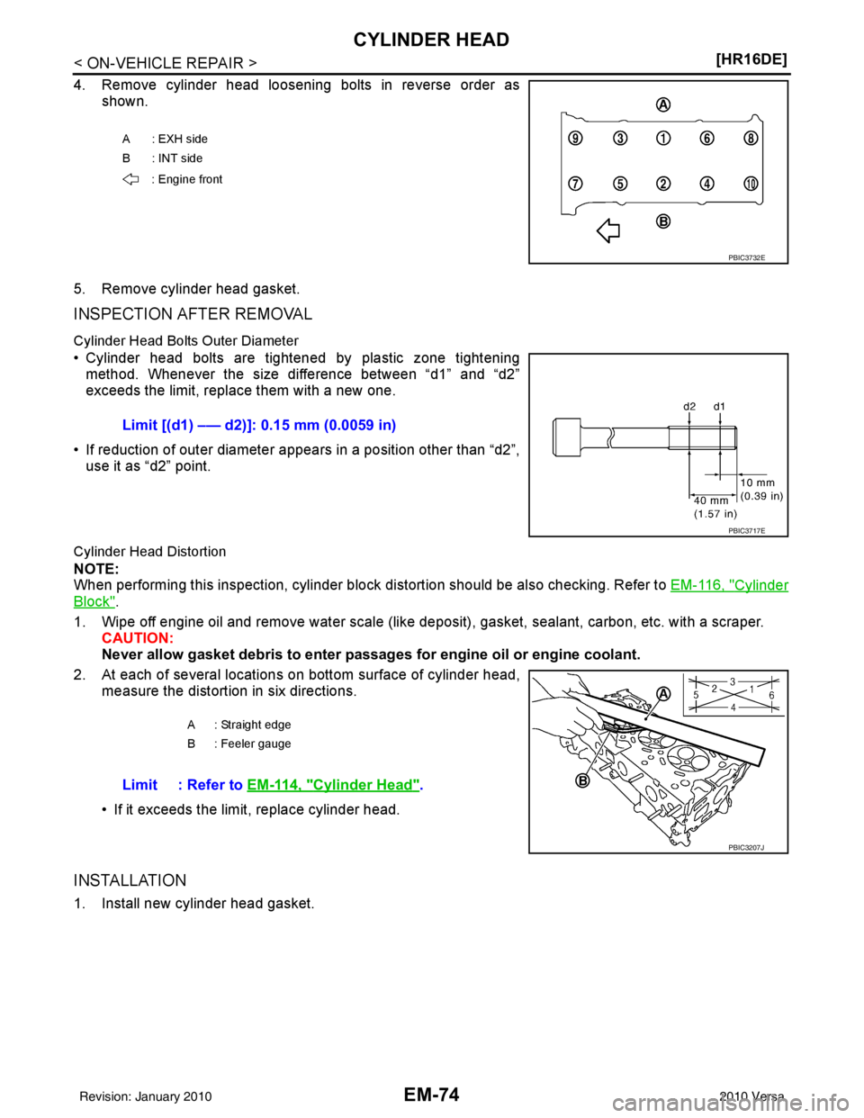
4. Remove cylinder head loosening bolts in reverse order as
shown.
5. Remove cylinder head gasket.
INSPECTION AFTER REMOVAL
Cylinder Head Bolt s Outer Diameter
• Cylinder head bolts are tightened by plastic zone tightening
method. Whenever the size difference between “d1” and “d2”
exceeds the limit, replace them with a new one.
• If reduction of outer diameter appear s in a position other than “d2”,
use it as “d2” point.
Cylinder Head Distortion
NOTE:
When performing this inspection, cylinder block distortion should be also checking. Refer to EM-116, "
Cylinder
Block".
1. Wipe off engine oil and remove water scale (like deposit ), gasket, sealant, carbon, etc. with a scraper.
CAUTION:
Never allow gasket debris to enter passag es for engine oil or engine coolant.
2. At each of several locations on bottom surface of cylinder head, measure the distortion in six directions.
• If it exceeds the limit, replace cylinder head.
INSTALLATION
1. Install new cylinder head gasket.
A : EXH side
B: INT side
: Engine front
PBIC3732E
Limit [(d1) –— d2)]: 0.15 mm (0.0059 in)
PBIC3717E
A : Straight edge
B : Feeler gauge
Limit : Refer to EM-114, "Cylinder Head".
PBIC3207J
Revision: January 20102010 Versa
Page 2492 of 3745
DRIVE BELTSEM-133
< SERVICE INFORMATION > [MR18DE]
C
D
E
F
G H
I
J
K L
M A
EM
NP
O
1. Install drive belt.
CAUTION:
Confirm drive belt is completely set to pulleys.
2. Release drive belt auto-tensioner, and apply tension to drive belt. WARNING:
Never place hand in a location where pinching m ay occur if the holding tool accidentally comes
off.
CAUTION:
Make sure no engine oil, working fluid and engine coolant are adhe red to drive belt and each pul-
ley groove.
3. Turn crankshaft pulley clockwise several times to equalize tension between each pulley.
4. Confirm tension of drive belt at indicator (notch on fixed side) is within the possible use range. Refer to
EM-132, "
Checking Drive Belts".
5. Install fender protector (RH). Refer to EI-24, "
Removal and Installation".
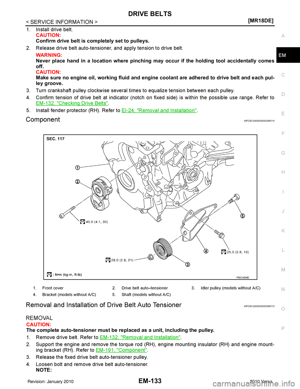
ComponentINFOID:0000000005398114
Removal and Installation of Drive Belt Auto TensionerINFOID:0000000005398115
REMOVAL
CAUTION:
The complete auto-tensioner must be re placed as a unit, including the pulley.
1. Remove drive belt. Refer to EM-132, "
Removal and Installation".
2. Support the engine and remove the torque rod (RH), engine mounting insulator (RH) and engine mount- ing bracket (RH). Refer to EM-191, "
Component".
3. Release the fixed drive belt auto-tensioner pulley.
4. Loosen bolt and remove drive belt auto-tensioner. NOTE:
1. Front cover 2. Drive belt auto–tensioner3. Idler pulley (models without A/C)
4. Bracket (models without A/C) 5. Shaft (models without A/C)
PBIC4698E
Revision: January 20102010 Versa
Page 2509 of 3745
EM-150
< SERVICE INFORMATION >[MR18DE]
IGNITION COIL, SPARK PLUG AND ROCKER COVER
3. Remove spark plug using suitable tool.
CAUTION:
Never drop or shock it.
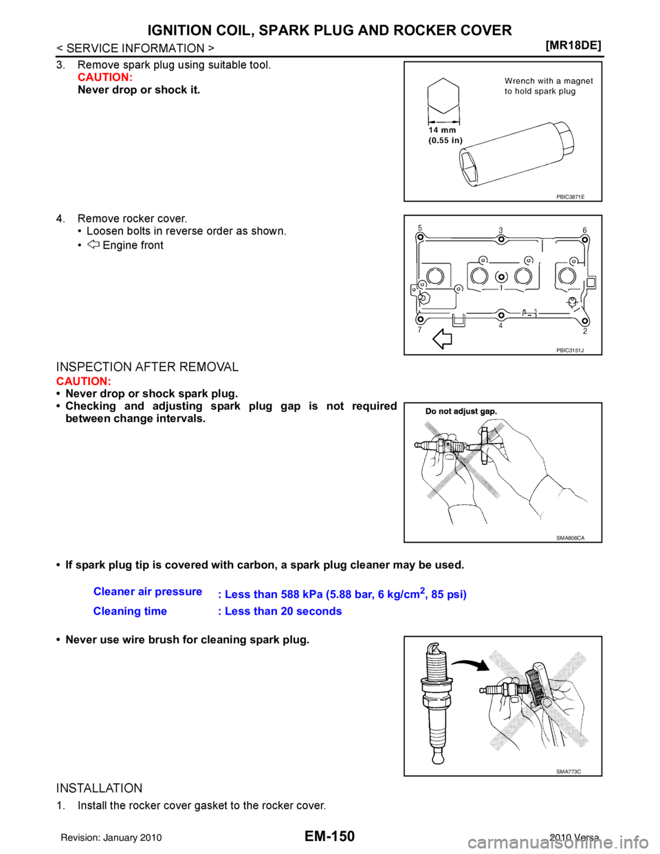
4. Remove rocker cover. • Loosen bolts in reverse order as shown.
• Engine front
INSPECTION AFTER REMOVAL
CAUTION:
• Never drop or shock spark plug.
• Checking and adjusting spar k plug gap is not required
between change intervals.
• If spark plug tip is covered with car bon, a spark plug cleaner may be used.
• Never use wire brush for cleaning spark plug.
INSTALLATION
1. Install the rocker cover gasket to the rocker cover.
PBIC3871E
PBIC3151J
SMA806CA
Cleaner air pressure : Less than 588 kPa (5.88 bar, 6 kg/cm2, 85 psi)
Cleaning time : Less than 20 seconds
SMA773C
Revision: January 20102010 Versa