2010 NISSAN LATIO checking oil
[x] Cancel search: checking oilPage 3290 of 3745
PREPARATIONMTC-11
< SERVICE INFORMATION >
C
DE
F
G H
I
K L
M A
B
MTC
N
O P
PREPARATION
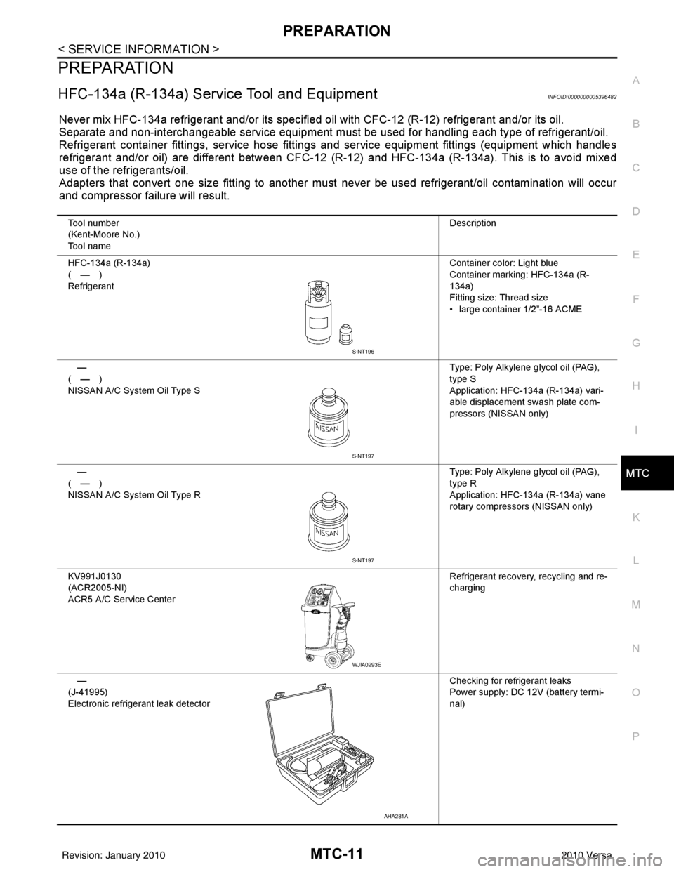
HFC-134a (R-134a) Service Tool and EquipmentINFOID:0000000005396482
Never mix HFC-134a refrigerant and/or its specified oil with CFC-12 (R-12) refrigerant and/or its oil.
Separate and non-interchangeable service equipment must be used for handling each type of refrigerant/oil.
Refrigerant container fittings, service hose fittings and service equipment fittings (equipment which handles
refrigerant and/or oil) are different between CFC-12 (R-12) and HFC-134a (R-134a). This is to avoid mixed
use of the refrigerants/oil.
Adapters that convert one size fitting to another must never be used refrigerant/oil contamination will occur
and compressor failure will result.
Tool number
(Kent-Moore No.)
Tool name Description
HFC-134a (R-134a)
(—)
Refrigerant Container color: Light blue
Container marking: HFC-134a (R-
134a)
Fitting size: Thread size
• large container 1/2”-16 ACME
—
(—)
NISSAN A/C System Oil Type S Type: Poly Alkylene glycol oil (PAG),
type S
Application: HFC-134a (R-134a) vari-
able displacement swash plate com-
pressors (NISSAN only)
—
(—)
NISSAN A/C System Oil Type R Type: Poly Alkylene glycol oil (PAG),
type R
Application: HFC-134a (R-134a) vane
rotary compressors (NISSAN only)
KV991J0130
(ACR2005-NI)
ACR5 A/C Se rvice Center Refrigerant recovery, recycling and re-
charging
—
(J-41995)
Electronic refrigerant leak detector Checking for refrigerant leaks
Power supply: DC 12V (battery termi-
nal)
S-NT196
S-NT197
S-NT197
WJIA0293E
AHA281A
Revision: January 20102010 Versa
Page 3331 of 3745
MTC-52
< SERVICE INFORMATION >
TROUBLE DIAGNOSIS
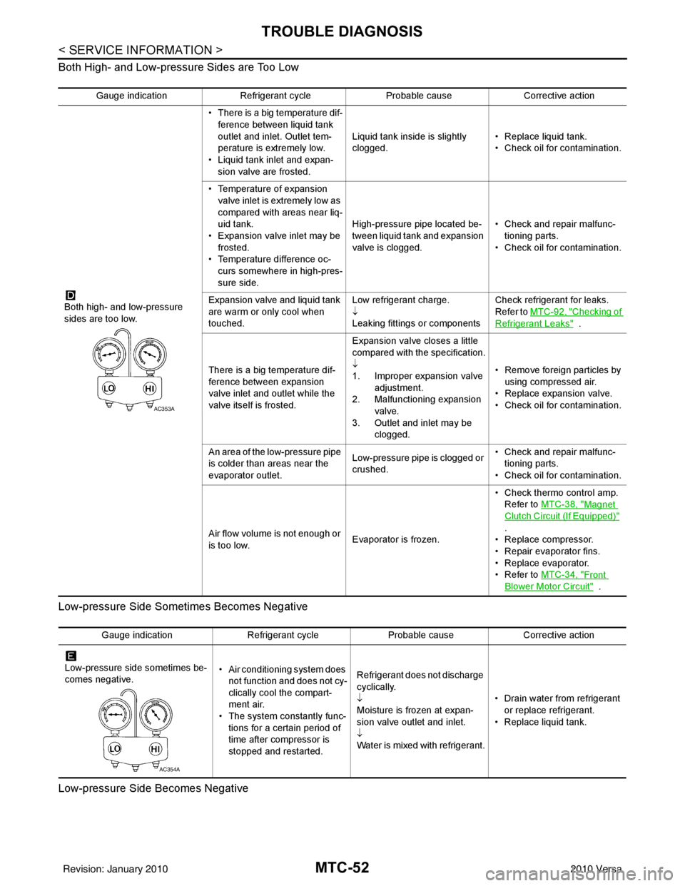
Both High- and Low-pressure Sides are Too Low
Low-pressure Side Sometimes Becomes Negative
Low-pressure Side Becomes Negative
Gauge indication Refrigerant cycle Probable causeCorrective action
Both high- and low-pressure
sides are too low. • There is a big temperature dif-
ference between liquid tank
outlet and inlet. Outlet tem-
perature is extremely low.
• Liquid tank inlet and expan- sion valve are frosted. Liquid tank inside is slightly
clogged.
• Replace liquid tank.
• Check oil for contamination.
• Temperature of expansion valve inlet is extremely low as
compared with areas near liq-
uid tank.
• Expansion valve inlet may be
frosted.
• Temperature difference oc- curs somewhere in high-pres-
sure side. High-pressure pipe located be-
tween liquid tank and expansion
valve is clogged.
• Check and repair malfunc-
tioning parts.
• Check oil for contamination.
Expansion valve and liquid tank
are warm or only cool when
touched. Low refrigerant charge.
↓
Leaking fittings or componentsCheck refrigerant for leaks.
Refer to
MTC-92, "
Checking of
Refrigerant Leaks" .
There is a big temperature dif-
ference between expansion
valve inlet and outlet while the
valve itself is frosted. Expansion valve closes a little
compared with the specification.
↓
1. Improper expansion valve
adjustment.
2. Malfunctioning expansion valve.
3. Outlet and inlet may be clogged. • Remove foreign particles by
using compressed air.
• Replace expansion valve.
• Check oil for contamination.
An area of the low-pressure pipe
is colder than areas near the
evaporator outlet. Low-pressure pipe is clogged or
crushed.• Check and repair malfunc-
tioning parts.
• Check oil for contamination.
Air flow volume is not enough or
is too low. Evaporator is frozen.• Check thermo control amp.
Refer to MTC-38, "
Magnet
Clutch Circuit (If Equipped)"
.
• Replace compressor.
• Repair evaporator fins.
• Replace evaporator.
•Refer to MTC-34, "
Front
Blower Motor Circuit" .
AC353A
Gauge indication Refrigerant cycleProbable causeCorrective action
Low-pressure side sometimes be-
comes negative. • Air conditioning system does
not function and does not cy-
clically cool the compart-
ment air.
• The system constantly func-
tions for a certain period of
time after compressor is
stopped and restarted. Refrigerant does not discharge
cyclically.
↓
Moisture is frozen at expan-
sion valve outlet and inlet.
↓
Water is mixed with refrigerant.
• Drain water from refrigerant
or replace refrigerant.
• Replace liquid tank.
AC354A
Revision: January 20102010 Versa
Page 3332 of 3745
TROUBLE DIAGNOSISMTC-53
< SERVICE INFORMATION >
C
DE
F
G H
I
K L
M A
B
MTC
N
O P
Insufficient HeatingINFOID:0000000005396504
SYMPTOM: Insufficient heating
INSPECTION FLOW
1.CONFIRM SYMPTOM BY PERFORMING OPERAT IONAL CHECK - TEMPERATURE INCREASE
1. Turn temperature control dial clockwise to maximum heat position.
2. Check for hot air at discharge air outlets.
Can the symptom be duplicated?
YES >> GO TO 3.
NO >> GO TO 2.
2.CHECK FOR ANY SYMPTOMS
Perform a complete operational check for any symptoms. Refer to MTC-31, "
Operational Check" .
Does another symptom exist?
YES >> Refer to MTC-23, "How to Perform Trouble Diagnosis for Quick and Accurate Repair" .
NO >> System OK.
3.CHECK FOR SERVICE BULLETINS
Check for any service bulletins.
>> GO TO 4.
4.CHECK COOLANT SYSTEM
1. Check engine coolant level. Refer to CO-12, "
Inspection" (HR16DE) or CO-36, "Inspection" (MR18DE).
2. Check hoses for leaks or kinks.
3. Check Radiator cap. Refer to CO-15, "
Checking Radiator Cap" HR16DE or CO-39, "Checking Radiator
Cap" (MR18DE).
OK or NG
OK >> GO TO 5.
NG >> Repair/replace as necessary.
5.CHECK AIR MIX DOOR CABLE
Check air mix door cable operation. Refer to MTC-65, "
Air Mix Door Cable Adjustment" .
OK or NG
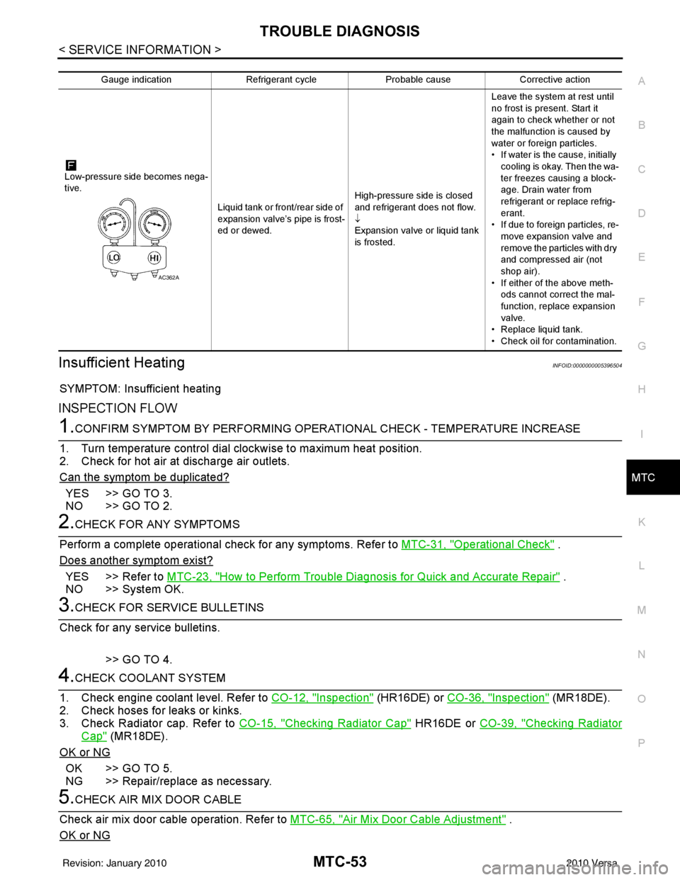
Gauge indication Refrigerant cycleProbable causeCorrective action
Low-pressure side becomes nega-
tive. Liquid tank or front/rear side of
expansion valve’s pipe is frost-
ed or dewed.High-pressure side is closed
and refrigerant does not flow.
↓
Expansion valve or liquid tank
is frosted.Leave the system at rest until
no frost is present. Start it
again to check whether or not
the malfunction is caused by
water or foreign particles.
• If water is the cause, initially
cooling is okay. Then the wa-
ter freezes causing a block-
age. Drain water from
refrigerant or replace refrig-
erant.
• If due to foreign particles, re-
move expansion valve and
remove the particles with dry
and compressed air (not
shop air).
• If either of the above meth- ods cannot correct the mal-
function, replace expansion
valve.
• Replace liquid tank.
• Check oil for contamination.
AC362A
Revision: January 20102010 Versa
Page 3334 of 3745
TROUBLE DIAGNOSISMTC-55
< SERVICE INFORMATION >
C
DE
F
G H
I
K L
M A
B
MTC
N
O P
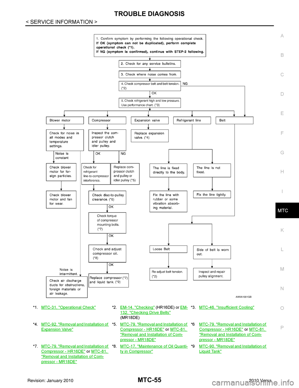
*1. MTC-31, "Operational Check"*2.EM-14, "Checking" (HR16DE) or EM-
132, "Checking Drive Belts"
(MR18DE) *3.
MTC-46, "
Insufficient Cooling"
*4.MTC-92, "Removal and Installation of
Expansion Valve"
*5.MTC-79, "Removal and Installation of
Compressor - HR16DE" or MTC-81,
"Removal and Installation of Com-
pressor - MR18DE"
*6 MTC-79, "Removal and Installation of
Compressor - HR16DE" or MTC-81,
"Removal and Installation of Com-
pressor - MR18DE"
*7. MTC-79, "Removal and Installation of
Compressor - HR16DE" or MTC-81,
"Removal and Installation of Com-
pressor - MR18DE"
*8.MTC-17, "Maintenance of Oil Quanti-
ty in Compressor"
*9 MTC-90, "Removal and Installation of
Liquid Tank"
AWIIA1001GB
Revision: January 20102010 Versa
Page 3355 of 3745
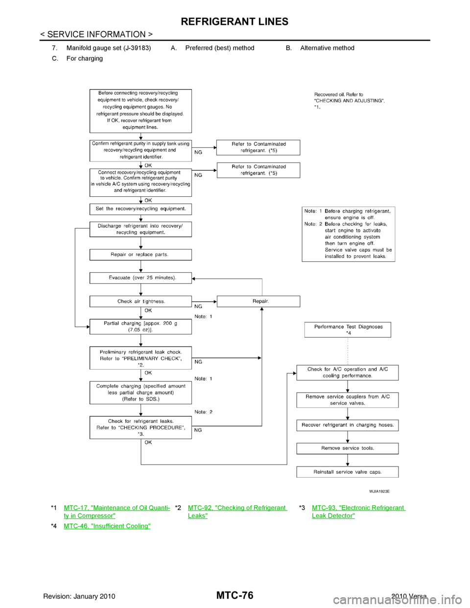
MTC-76
< SERVICE INFORMATION >
REFRIGERANT LINES
7. Manifold gauge set (J-39183) A. Preferred (best) method B. Alternative method
C. For charging
*1 MTC-17, "
Maintenance of Oil Quanti-
ty in Compressor"
*2MTC-92, "Checking of Refrigerant
Leaks"
*3MTC-93, "Electronic Refrigerant
Leak Detector"
*4MTC-46, "Insufficient Cooling"
WJIA1923E
Revision: January 20102010 Versa
Page 3359 of 3745
MTC-80
< SERVICE INFORMATION >
REFRIGERANT LINES
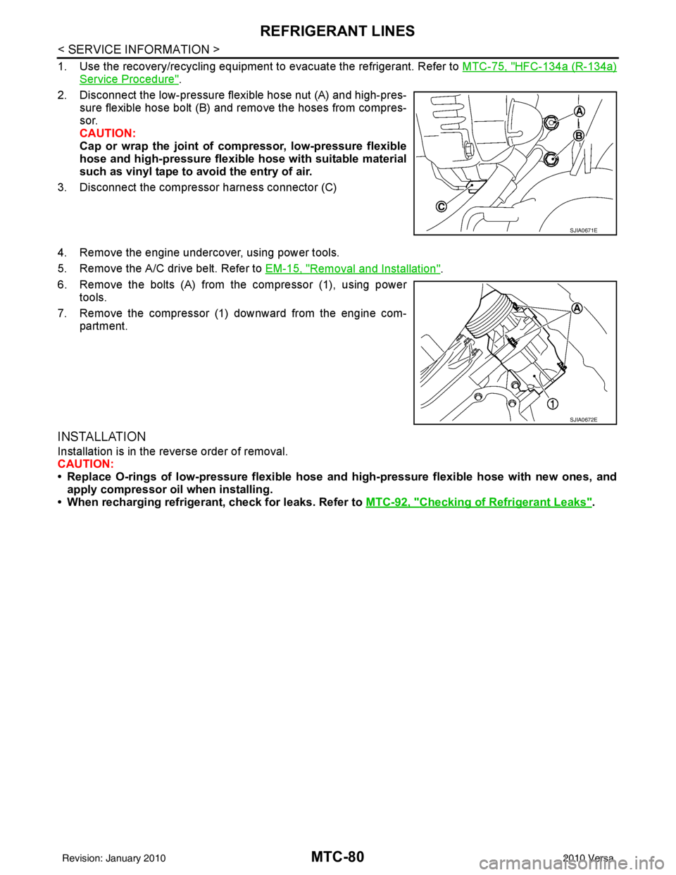
1. Use the recovery/recycling equipment to evacuate the refrigerant. Refer to MTC-75, "HFC-134a (R-134a)
Service Procedure".
2. Disconnect the low-pressure flexible hose nut (A) and high-pres- sure flexible hose bolt (B) and remove the hoses from compres-
sor.
CAUTION:
Cap or wrap the joint of co mpressor, low-pressure flexible
hose and high-pressure flexibl e hose with suitable material
such as vinyl tape to avoid the entry of air.
3. Disconnect the compressor harness connector (C)
4. Remove the engine undercover, using power tools.
5. Remove the A/C drive belt. Refer to EM-15, "
Removal and Installation".
6. Remove the bolts (A) from the compressor (1), using power tools.
7. Remove the compressor (1) downward from the engine com- partment.
INSTALLATION
Installation is in the reverse order of removal.
CAUTION:
• Replace O-rings of low-pressure flexible hose an d high-pressure flexible hose with new ones, and
apply compressor oil when installing.
• When recharging refrigerant, check for leaks. Refer to MTC-92, "
Checking of Refrigerant Leaks".
SJIA0671E
SJIA0672E
Revision: January 20102010 Versa
Page 3361 of 3745
MTC-82
< SERVICE INFORMATION >
REFRIGERANT LINES
INSTALLATION
Installation is in the reverse order of removal.
CAUTION:
• Replace O-rings of low-pressure flexible hose and high-pressure flexible hose with a new ones, andapply compressor oil when installing.
• When recharging refrigerant, check for leaks. Refer to MTC-92, "
Checking of Refrigerant Leaks".
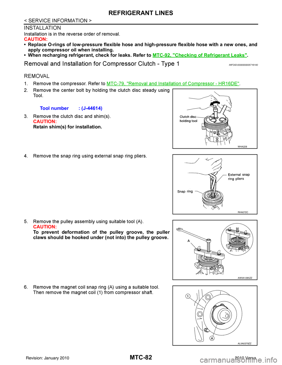
Removal and Installation for Compressor Clutch - Type 1INFOID:0000000005716140
REMOVAL
1. Remove the compressor. Refer to MTC-79, "Removal and Installation of Compressor - HR16DE".
2. Remove the center bolt by holding the clutch disc steady using Tool.
3. Remove the clutch disc and shim(s). CAUTION:
Retain shim(s) for installation.
4. Remove the snap ring using external snap ring pliers.
5. Remove the pulley assembly using suitable tool (A). CAUTION:
To prevent deformation of th e pulley groove, the puller
claws should be ho oked under (not into) the pulley groove.
6. Remove the magnet coil snap ring (A) using a suitable tool. Then remove the magnet coil (1) from compressor shaft.Tool number : (J-44614)
WHA228
RHA072C
AWIIA1285ZZ
ALIIA0379ZZ
Revision: January 20102010 Versa
Page 3370 of 3745
REFRIGERANT LINESMTC-91
< SERVICE INFORMATION >
C
DE
F
G H
I
K L
M A
B
MTC
N
O P
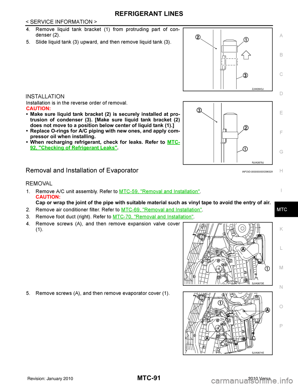
4. Remove liquid tank bracket (1 ) from protruding part of con-
denser (2).
5. Slide liquid tank (3) upward, and then remove liquid tank (3).
INSTALLATION
Installation is in the reverse order of removal.
CAUTION:
• Make sure liquid tank bracket (2) is securely installed at pro- trusion of condenser (3). [Make sure liquid tank bracket (2)
does not move to a position belo w center of liquid tank (1).]
• Replace O-rings for A/C piping with new ones, and apply com-
pressor oil when installing.
• When recharging refrigerant, check for leaks. Refer to MTC-
92, "Checking of Refrigerant Leaks".
Removal and Installation of EvaporatorINFOID:0000000005396529
REMOVAL
1. Remove A/C unit assembly. Refer to MTC-59, "Removal and Installation".
CAUTION:
Cap or wrap the joint of the pipe with suitable ma terial such as vinyl tape to avoid the entry of air.
2. Remove air conditioner filter. Refer to MTC-69, "
Removal and Installation".
3. Remove foot duct (right). Refer to MTC-70, "
Removal and Installation".
4. Remove screws (A), and then remove expansion valve cover (1).
5. Remove screws (A), and then remove evaporator cover (1).
ZJIA0843J
RJIA3879J
SJIA0673E
SJIA0674E
Revision: January 20102010 Versa