2010 NISSAN LATIO checking oil
[x] Cancel search: checking oilPage 1037 of 3745
CVT-4
CONSULT-III Reference Value in Data Monitor
Mode .................................................................... ..
135
Wiring Diagram - CVT - ODSW .............................136
Diagnosis Procedure .............................................136
Component Inspection ...........................................138
SHIFT POSITION INDICATOR CIRCUIT ........140
Description ........................................................... ..140
CONSULT-III Reference Value in Data Monitor
Mode .................................................................... ..
140
Diagnosis Procedure .............................................140
TROUBLE DIAGNOSIS FOR SYMPTOMS .....141
Wiring Diagram - CVT - NONDTC ....................... ..141
O/D OFF Indicator Lamp Does Not Come On .......143
Engine Cannot Be Started in "P" and "N" Position ..145
In "P" Position, Vehicle Moves Forward or Back-
ward When Pushed ...............................................
145
In "N" Position, Vehicle Moves ............................ ..146
Large Shock "N" → "R" Position .......................... ..146
Vehicle Does Not Creep Backward in "R" Position ..147
Vehicle Does Not Creep Forward in "D" or "L" Po-
sition ......................................................................
148
Vehicle Speed Does Not Change in "L" Position ...149
Vehicle Speed Does Not Change in overdrive-off
mode ......................................................................
150
Vehicle Speed Does Not Change in "D" Position ..151
Vehicle Does Not Decelerate by Engine Brake .....151
CVT SHIFT LOCK SYSTEM ........................... .153
Description ........................................................... ..153
Shift Lock System Electrical Parts Location ..........154
Wiring Diagram - CVT - SHIFT ..............................155
Diagnosis Procedure .............................................155
TCM ..................................................................159
Removal and Installation ..................................... ..159
SHIFT CONTROL SYSTEM ............................160
Removal and Installation .......................................160
CVT Shift Selector Disa ssembly and Assembly .. .163
Shift Lever Handle Removal and Installation ....... .163
Adjustment of CVT Position ................................. .164
Checking of CVT Position .....................................164
KEY INTERLOCK CABLE ...............................166
Removal and Installation .......................................166
PRIMARY SPEED SENSOR .......................... ..169
Exploded View ..................................................... .169
Removal and Installation .......................................169
Inspection ............................................................. .169
SECONDARY SPEED SENSOR ......................170
Exploded View ..................................................... .170
Removal and Installation .......................................170
Inspection ............................................................. .170
AIR BREATHER HOSE ....................................171
Removal and Installation .......................................171
DIFFERENTIAL SIDE OIL SEAL .....................172
Removal and Installation .......................................172
TRANSAXLE ASSEMBLY ............................. ..173
Removal and Installation .......................................173
SERVICE DATA AND SPECIFICATIONS
(SDS) .............................................................. ..
176
General Specification ........................................... .176
Vehicle Speed When Shifting Gears .....................176
Stall Speed ............................................................176
Line Pressure ........................................................176
Solenoid Valves ....................................................177
CVT Fluid Temperature Sensor ............................177
Primary Speed Sensor ..........................................177
Secondary Speed Sensor .................................... .177
Removal and Installation .......................................177
Revision: January 20102010 Versa
Page 1048 of 3745
CVT FLUIDCVT-15
< SERVICE INFORMATION > [RE0F08B]
D
E
F
G H
I
J
K L
M A
B
CVT
N
O P
FLUID CONDITION CHECK
Changing CVT FluidINFOID:0000000005397768
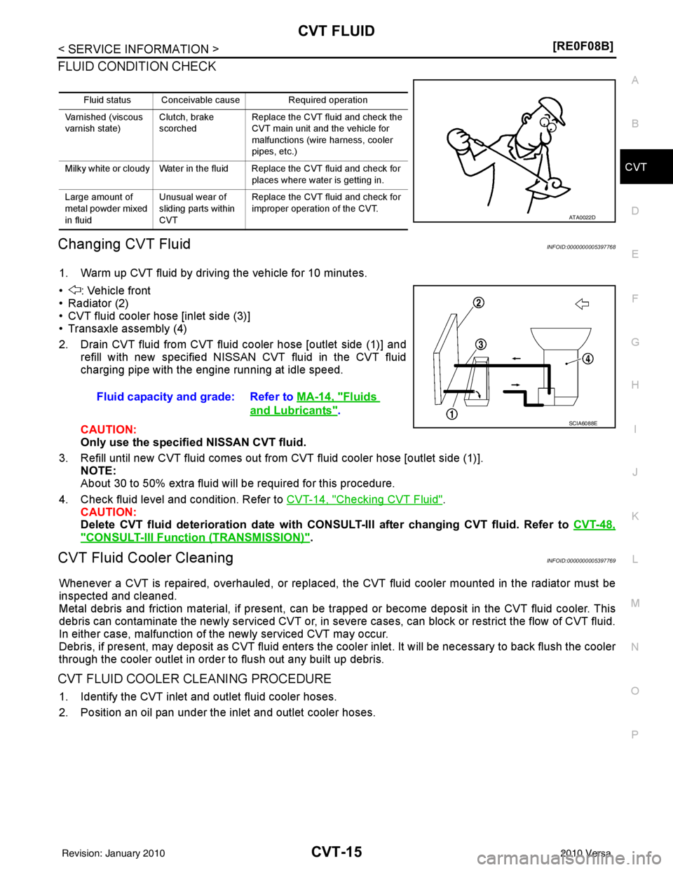
1. Warm up CVT fluid by driving the vehicle for 10 minutes.
• : Vehicle front
• Radiator (2)
• CVT fluid cooler hose [inlet side (3)]
• Transaxle assembly (4)
2. Drain CVT fluid from CVT fluid cooler hose [outlet side (1)] and refill with new specified NISSAN CVT fluid in the CVT fluid
charging pipe with the engine running at idle speed.
CAUTION:
Only use the specifi ed NISSAN CVT fluid.
3. Refill until new CVT fluid comes out from CVT fluid cooler hose [outlet side (1)]. NOTE:
About 30 to 50% extra fluid will be required for this procedure.
4. Check fluid level and condition. Refer to CVT-14, "
Checking CVT Fluid".
CAUTION:
Delete CVT fluid deterioration date with CONSULT-III after changing CVT fluid. Refer to CVT-48,
"CONSULT-III Function (TRANSMISSION)".
CVT Fluid Cooler CleaningINFOID:0000000005397769
Whenever a CVT is repaired, overhauled, or replaced, the CVT fluid cooler mounted in the radiator must be
inspected and cleaned.
Metal debris and friction material, if present, can be trapped or become deposit in the CVT fluid cooler. This
debris can contaminate the newly serviced CVT or, in severe cases, can block or restrict the flow of CVT fluid.
In either case, malfunction of the newly serviced CVT may occur.
Debris, if present, may deposit as CVT fluid enters the cool er inlet. It will be necessary to back flush the cooler
through the cooler outlet in order to flush out any built up debris.
CVT FLUID COOLER CLEANING PROCEDURE
1. Identify the CVT inlet and outlet fluid cooler hoses.
2. Position an oil pan under the inlet and outlet cooler hoses.
Fluid status Conceivable cause Required operation
Varnished (viscous
varnish state) Clutch, brake
scorchedReplace the CVT fluid and check the
CVT main unit and the vehicle for
malfunctions (wire harness, cooler
pipes, etc.)
Milky white or cloudy Water in the fluid Replace the CVT fluid and check for places where water is getting in.
Large amount of
metal powder mixed
in fluid Unusual wear of
sliding parts within
CVTReplace the CVT fluid and check for
improper operation of the CVT.
ATA0022D
Fluid capacity and grade: Refer to
MA-14, "Fluids
and Lubricants".SCIA6088E
Revision: January 20102010 Versa
Page 1071 of 3745
CVT-38
< SERVICE INFORMATION >[RE0F08B]
TROUBLE DIAGNOSIS
• Inspect for fluid leakage and check the fluid level. Refer to
CVT-14, "Checking CVT Fluid" .
Fluid Condition Check
Inspect the fluid condition.
STALL TEST
Stall Test Procedure
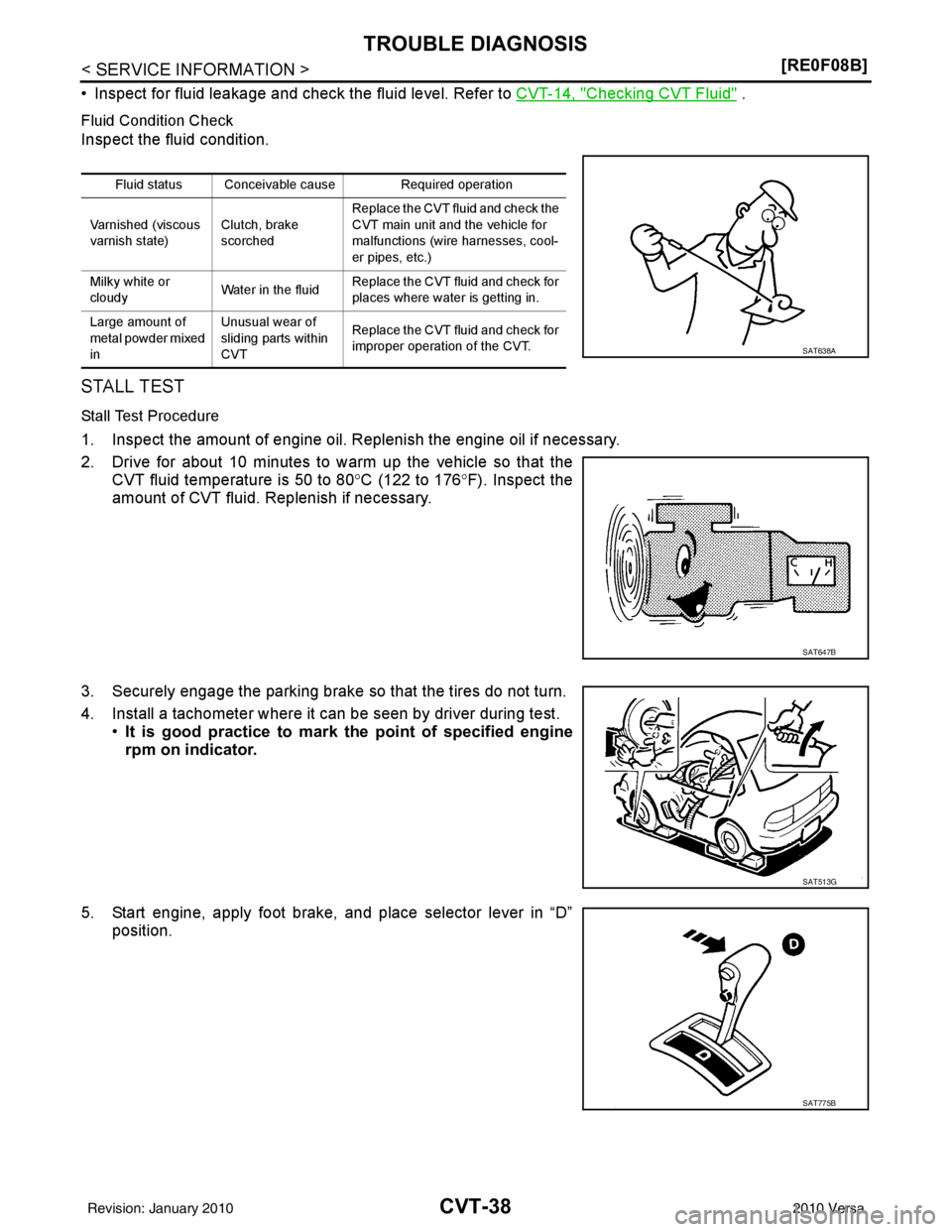
1. Inspect the amount of engine oil. Replenish the engine oil if necessary.
2. Drive for about 10 minutes to warm up the vehicle so that the
CVT fluid temperature is 50 to 80 °C (122 to 176° F). Inspect the
amount of CVT fluid. Replenish if necessary.
3. Securely engage the parking brake so that the tires do not turn.
4. Install a tachometer where it can be seen by driver during test. •It is good practice to mark the point of specified engine
rpm on indicator.
5. Start engine, apply foot brake, and place selector lever in “D” position.
Fluid status Conceivable cause Required operation
Varnished (viscous
varnish state) Clutch, brake
scorchedReplace the CVT fluid and check the
CVT main unit and the vehicle for
malfunctions (wire harnesses, cool-
er pipes, etc.)
Milky white or
cloudy Water in the fluidReplace the CVT fluid and check for
places where water is getting in.
Large amount of
metal powder mixed
in Unusual wear of
sliding parts within
CVT
Replace the CVT fluid and check for
improper operation of the CVT.
SAT638A
SAT647B
SAT513G
SAT775B
Revision: January 20102010 Versa
Page 1205 of 3745
CVT-172
< SERVICE INFORMATION >[RE0F08B]
DIFFERENTIAL SIDE OIL SEAL
DIFFERENTIAL SIDE OIL SEAL
Removal and InstallationINFOID:0000000005398012
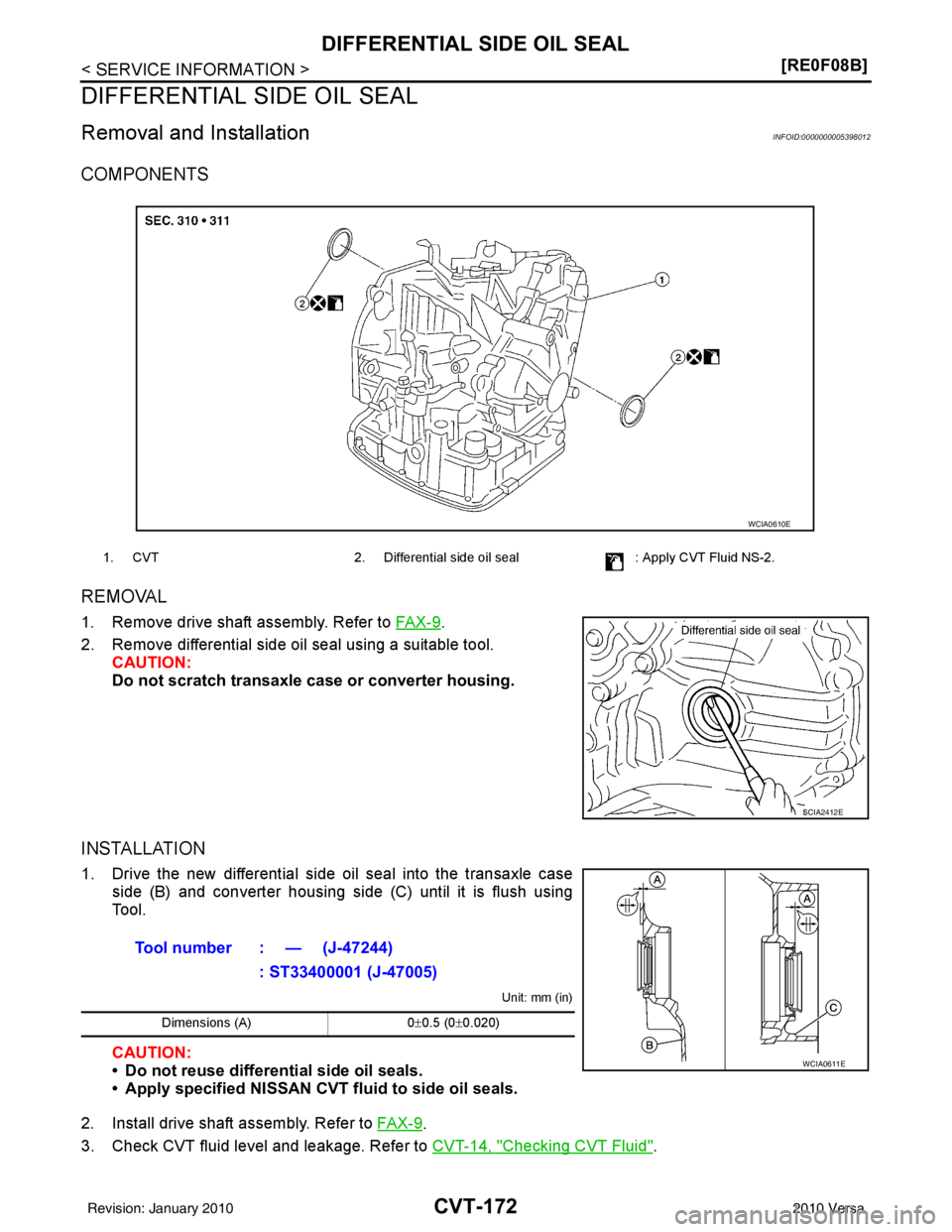
COMPONENTS
REMOVAL
1. Remove drive shaft assembly. Refer to
FAX-9.
2. Remove differential side oil seal using a suitable tool. CAUTION:
Do not scratch transaxle case or converter housing.
INSTALLATION
1. Drive the new differential side oil seal into the transaxle caseside (B) and converter housing side (C) until it is flush using
Tool.
Unit: mm (in)
CAUTION:
• Do not reuse differential side oil seals.
• Apply specified NISSAN CVT fluid to side oil seals.
2. Install drive shaft assembly. Refer to FA X - 9
.
3. Check CVT fluid level and leakage. Refer to CVT-14, "
Checking CVT Fluid".
1. CVT2. Differential side oil seal : Apply CVT Fluid NS-2.
WCIA0610E
SCIA2412E
Tool number : — (J-47244)
: ST33400001 (J-47005)
Dimensions (A) 0±0.5 (0 ±0.020)
WCIA0611E
Revision: January 20102010 Versa
Page 1514 of 3745
P0300, P0301, P0302, P0303, P0304 MISFIRE
EC-249
< COMPONENT DIAGNOSIS > [HR16DE]
C
D
E
F
G H
I
J
K L
M A
EC
NP
O
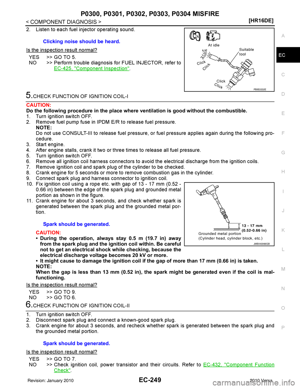
2. Listen to each fuel injector operating sound.
Is the inspection result normal?
YES >> GO TO 5.
NO >> Perform trouble diagnosis for FUEL INJECTOR, refer to
EC-425, "
Component Inspection".
5.CHECK FUNCTION OF IGNITION COIL-I
CAUTION:
Do the following procedure in the place where ventilation is good without the combustible.
1. Turn ignition switch OFF.
2. Remove fuel pump fuse in IPDM E/R to release fuel pressure.
NOTE:
Do not use CONSULT-III to release fuel pressure, or fuel pressure applies again during the following pro-
cedure.
3. Start engine.
4. After engine stalls, crank it two or three times to release all fuel pressure.
5. Turn ignition switch OFF.
6. Remove all ignition coil harness connectors to avoid the electrical discharge from the ignition coils.
7. Remove ignition coil and spark plug of the cylinder to be checked.
8. Crank engine for 5 seconds or more to remove combustion gas in the cylinder.
9. Connect spark plug and harness connector to ignition coil.
10. Fix ignition coil using a rope etc. with gap of 13 - 17 mm (0.52 - 0.66 in) between the edge of the spark plug and grounded metal
portion as shown in the figure.
11. Crank engine for about 3 seconds, and check whether spark is
generated between the spark plug and the grounded metal por-
tion.
CAUTION:
• During the operation, alw ays stay 0.5 m (19.7 in) away
from the spark plug and the ig nition coil within. Be careful
not to get an electrical sh ock while checking, because the
electrical discharge voltage becomes 20 kV or more.
• It might cause to damage the igni tion coil if the gap of more than 17 mm (0.66 in) is taken.
NOTE:
When the gap is less than 13 mm (0.52 in), the sp ark might be generated even if the coil is mal-
functioning.
Is the inspection result normal?
YES >> GO TO 9.
NO >> GO TO 6.
6.CHECK FUNCTION OF IGNITION COIL-II
1. Turn ignition switch OFF.
2. Disconnect spark plug and connect a known-good spark plug.
3. Crank engine for about 3 seconds, and recheck whether spark is generated between the spark plug and the grounded metal portion.
Is the inspection result normal?
YES >> GO TO 7.
NO >> Check ignition coil, power transistor and their circuits. Refer to EC-432, "
Component Function
Check".
Clicking noise should be heard.
PBIB3332E
Spark should be generated.
JMBIA0066GB
Spark should be generated.
Revision: January 20102010 Versa
Page 1535 of 3745
EC-270
< COMPONENT DIAGNOSIS >[HR16DE]
P0420 THREE WAY CATALYST FUNCTION
Do the following procedure in the place where ventilation is good without the combustible.
1. Turn ignition switch OFF.
2. Remove fuel pump fuse in IPDM E/R to release fuel pressure.
NOTE:
Do not use CONSULT-III to release fuel pressure, or fuel pressure applies again during the following pro-
cedure.
3. Start engine.
4. After engine stalls, crank it two or three times to release all fuel pressure.
5. Turn ignition switch OFF.
6. Remove all ignition coil harness connectors to avoi d the electrical discharge from the ignition coils.
7. Remove ignition coil and spark plug of the cylinder to be checked.
8. Crank engine for 5 seconds or more to remove combustion gas in the cylinder.
9. Connect spark plug and harness connector to ignition coil.
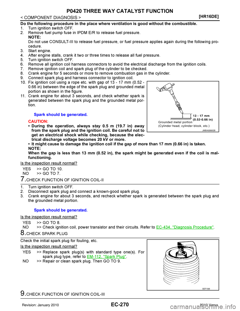
10. Fix ignition coil using a rope etc. with gap of 13 - 17 mm (0.52 - 0.66 in) between the edge of the spark plug and grounded metal
portion as shown in the figure.
11. Crank engine for about 3 seconds, and check whether spark is generated between the spark plug and the grounded metal por-
tion.
CAUTION:
• During the operation, always stay 0.5 m (19.7 in) awayfrom the spark plug and the ignition coil. Be careful not to
get an electrical shock wh ile checking, because the elec-
trical discharge voltage becomes 20 kV or more.
• It might cause to damage the igni tion coil if the gap of more than 17 mm (0.66 in) is taken.
NOTE:
When the gap is less than 13 mm (0.52 in), the sp ark might be generated even if the coil is mal-
functioning.
Is the inspection result normal?
YES >> GO TO 10.
NO >> GO TO 7.
7.CHECK FUNCTION OF IGNITION COIL-II
1. Turn ignition switch OFF.
2. Disconnect spark plug and connect a known-good spark plug.
3. Crank engine for about 3 seconds, and recheck whether spark is generated between the spark plug and the grounded metal portion.
Is the inspection result normal?
YES >> GO TO 8.
NO >> Check ignition coil, power transistor and their circuits. Refer to EC-434, "
Diagnosis Procedure".
8.CHECK SPARK PLUG
Check the initial spark plug for fouling, etc.
Is the inspection result normal?
YES >> Replace spark plug(s) with standard type one(s). For spark plug type, refer to EM-112, "
Spark Plug".
NO >> Repair or clean spark plug. Then GO TO 9.
9.CHECK FUNCTION OF IGNITION COIL-III Spark should be generated.
JMBIA0066GB
Spark should be generated.
SEF156I
Revision: January 20102010 Versa
Page 1703 of 3745
EC-438
< COMPONENT DIAGNOSIS >[HR16DE]
IGNITION SIGNAL
10. Connect spark plug and harness connector to ignition coil.
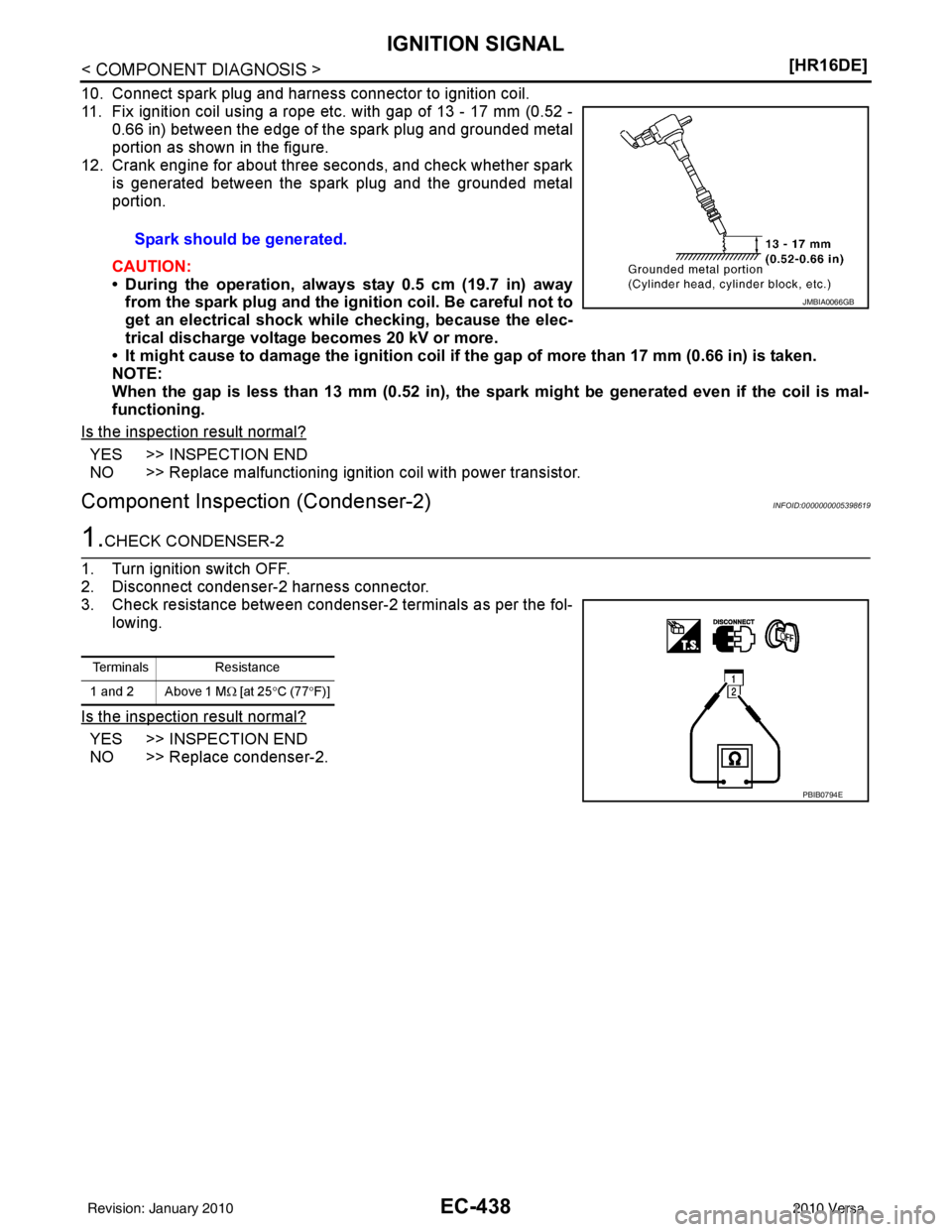
11. Fix ignition coil using a rope etc. with gap of 13 - 17 mm (0.52 -
0.66 in) between the edge of the spark plug and grounded metal
portion as shown in the figure.
12. Crank engine for about three seconds, and check whether spark is generated between the spark plug and the grounded metal
portion.
CAUTION:
• During the operation, alw ays stay 0.5 cm (19.7 in) away
from the spark plug and the ignition coil. Be careful not to
get an electrical shock wh ile checking, because the elec-
trical discharge voltage becomes 20 kV or more.
• It might cause to damage the igni tion coil if the gap of more than 17 mm (0.66 in) is taken.
NOTE:
When the gap is less than 13 mm (0.52 in), the sp ark might be generated even if the coil is mal-
functioning.
Is the inspection result normal?
YES >> INSPECTION END
NO >> Replace malfunctioning ignition coil with power transistor.
Component Inspection (Condenser-2)INFOID:0000000005398619
1.CHECK CONDENSER-2
1. Turn ignition switch OFF.
2. Disconnect condenser-2 harness connector.
3. Check resistance between condenser-2 terminals as per the fol- lowing.
Is the inspection result normal?
YES >> INSPECTION END
NO >> Replace condenser-2. Spark should be generated.
JMBIA0066GB
Terminals
Resistance
1 and 2 Above 1 M Ω [at 25 °C (77 °F)]
PBIB0794E
Revision: January 20102010 Versa
Page 1848 of 3745
BASIC SERVICE PROCEDUREEC-583
< SERVICE INFORMATION > [MR18DE]
C
D
E
F
G H
I
J
K L
M A
EC
NP
O
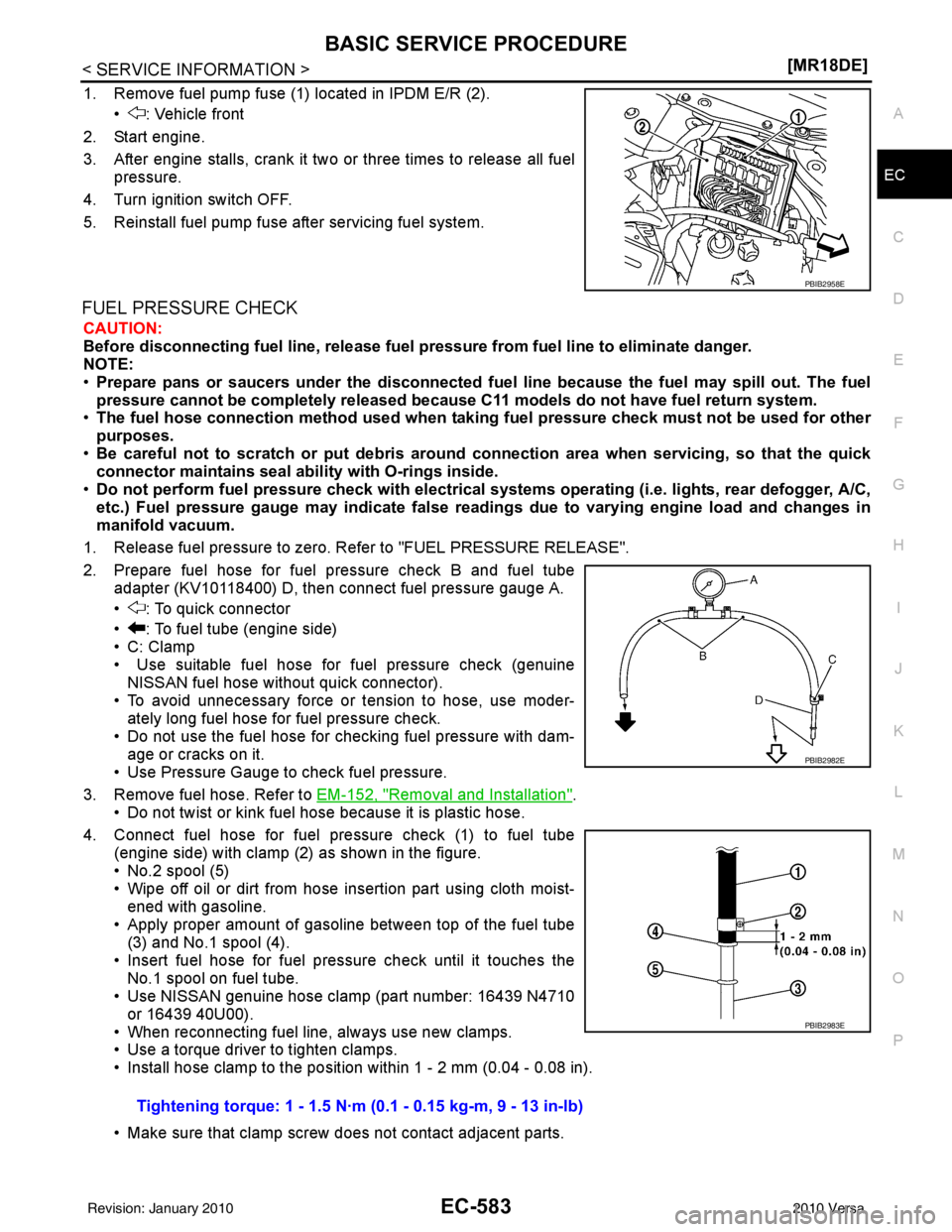
1. Remove fuel pump fuse (1) located in IPDM E/R (2).
• : Vehicle front
2. Start engine.
3. After engine stalls, crank it two or three times to release all fuel pressure.
4. Turn ignition switch OFF.
5. Reinstall fuel pump fuse after servicing fuel system.
FUEL PRESSURE CHECK
CAUTION:
Before disconnecting fuel line, release fuel pressure from fuel line to eliminate danger.
NOTE:
• Prepare pans or saucers under the disconnected fuel line because the fuel may spill out. The fuel
pressure cannot be completely released because C11 models do not have fuel return system.
• The fuel hose connection method used when taking fuel pressure check must not be used for other
purposes.
• Be careful not to scratch or put debris around connection area when servicing, so that the quick
connector maintains seal abil ity with O-rings inside.
• Do not perform fuel pressure check with electrical systems operating (i.e. lights, rear defogger, A/C,
etc.) Fuel pressure gauge may indicate false readin gs due to varying engine load and changes in
manifold vacuum.
1. Release fuel pressure to zero. Refer to "FUEL PRESSURE RELEASE".
2. Prepare fuel hose for fuel pressure check B and fuel tube adapter (KV10118400) D, then connect fuel pressure gauge A.
• : To quick connector
• : To fuel tube (engine side)
• C: Clamp
• Use suitable fuel hose for fuel pressure check (genuineNISSAN fuel hose without quick connector).
• To avoid unnecessary force or tension to hose, use moder- ately long fuel hose for fuel pressure check.
• Do not use the fuel hose for checking fuel pressure with dam- age or cracks on it.
• Use Pressure Gauge to check fuel pressure.
3. Remove fuel hose. Refer to EM-152, "
Removal and Installation".
• Do not twist or kink fuel hose because it is plastic hose.
4. Connect fuel hose for fuel pressure check (1) to fuel tube (engine side) with clamp (2) as shown in the figure.
• No.2 spool (5)
• Wipe off oil or dirt from hose insertion part using cloth moist-ened with gasoline.
• Apply proper amount of gasoline between top of the fuel tube (3) and No.1 spool (4).
• Insert fuel hose for fuel pressure check until it touches the No.1 spool on fuel tube.
• Use NISSAN genuine hose clamp (part number: 16439 N4710
or 16439 40U00).
• When reconnecting fuel line, always use new clamps.
• Use a torque driver to tighten clamps.
• Install hose clamp to the positi on within 1 - 2 mm (0.04 - 0.08 in).
• Make sure that clamp screw does not contact adjacent parts.
PBIB2958E
Tightening torque: 1 - 1.5 N·m (0.1 - 0.15 kg-m, 9 - 13 in-lb)
PBIB2982E
PBIB2983E
Revision: January 20102010 Versa