Page 511 of 658

6-2 For emergencies
6If the vehicle breaks down
N00836300145
If your vehicle breaks down on the road, move to the shoulder
and turn on the hazard warning flashers. If there is no shoulder,
or the shoulder is not safe, drive in the right lane slowly, with
the hazard lights flashing, until you come to a safe stopping
place. Keep the flashers flashing. If the engine stops/fails If the engine stops, there will be no power assist to the steering
and brakes, making these difficult to use.�
The brake booster will not work, so the brakes will not
grip well. The brake pedal will be harder to press than
usual.
�
Since there is no power steering assist, the steering wheel
will be hard to turn. Turning the steering wheel requires
more effort than usual.
When the engine fails at the intersection Get help from your passengers, bystanders, etc. to push the
vehicle and move it to a safe zone.
Jump-starting the engine
N00836400654
If the engine cannot be started because the battery is weak or
dead, you can start it with the battery from another vehicle
using jumper cables.
1. Take off any metal jewelry such as watch bands or brace-
lets that might make an accidental electrical contact.
2. Position the vehicles close enough together so that the
jumper cables can reach, but be sure the vehicles aren’t
touching each other.
WA R N I N G
!�
When using jumper cables to start a vehicle, follow
the procedures and be very cautious. CAUTION
!�
Do not try to start your vehicle by pushing or tow-
ing. Vehicles equipped with continuously variable
transmission (CVT) or Twin Clutch SST cannot be
started this way. Pushing or towing a vehicle that
has a manual transaxle may overheat and damage
the catalytic converter. Also, there is more risk of an
accident when a vehicle is being pushed or towed.CAUTION
!�
Check the other vehicle. It must have a 12-volt bat-
tery. If the other system isn’t 12-volt, both systems
can be damaged.
BK0103001US.book 2 ページ 2009年8月20日 木曜日 午前10時45分
Page 512 of 658

For emergencies
6-3
6
3. You could be injured if the vehicles move. Set the parking
brake firmly on each vehicle. Put an automatic transaxle,
CVT or Twin Clutch SST in “P” (PARK) or a manual
transaxle in “N” (Neutral). Turn the ignition switch to the
“LOCK” position. NOTE�
Turn off all lights, heater, and other electrical loads. This
will avoid sparks and help save both batteries.
4. Make sure your battery electrolyte is at the proper level.
(Refer to “Checking battery electrolyte level” on page 7-
26.)5. For vehicles equipped with turbocharger, remove the air
duct and then the battery upper cover.
(Refer to “Removing and installing the battery upper
cover” on page 7-23.)
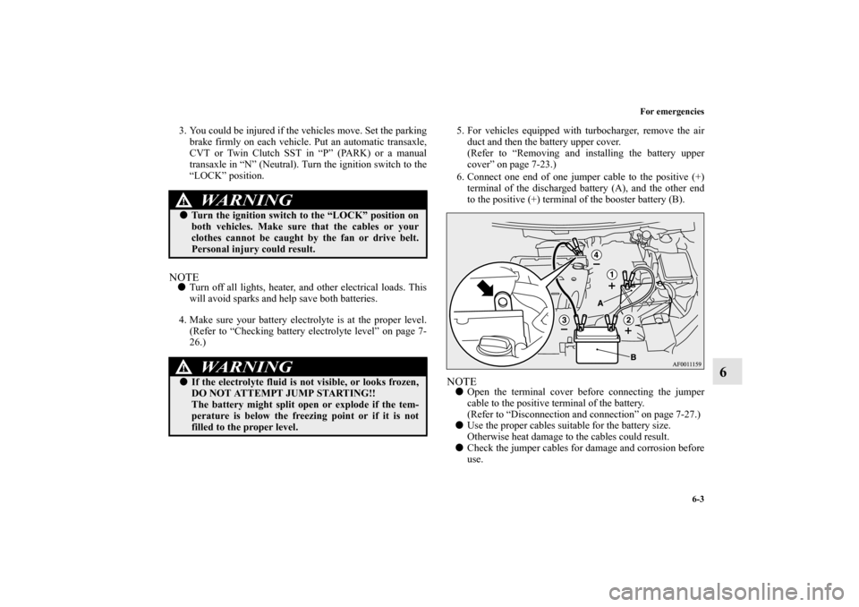
6. Connect one end of one jumper cable to the positive (+)
terminal of the discharged battery (A), and the other end
to the positive (+) terminal of the booster battery (B).
NOTE�
Open the terminal cover before connecting the jumper
cable to the positive terminal of the battery.
(Refer to “Disconnection and connection” on page 7-27.)
�
Use the proper cables suitable for the battery size.
Otherwise heat damage to the cables could result.
�
Check the jumper cables for damage and corrosion before
use.
WA R N I N G
!�
Turn the ignition switch to the “LOCK” position on
both vehicles. Make sure that the cables or your
clothes cannot be caught by the fan or drive belt.
Personal injury could result. WA R N I N G
!�
If the electrolyte fluid is not visible, or looks frozen,
DO NOT ATTEMPT JUMP STARTING!!
The battery might split open or explode if the tem-
perature is below the freezing point or if it is not
filled to the proper level.
BK0103001US.book 3 ページ 2009年8月20日 木曜日 午前10時45分
Page 583 of 658
7-52 Vehicle care and maintenance
7
*- Fusible link�
Some fuses may not be installed on your vehicle, depend-
ing on the vehicle model or specifications.
�
The table above shows the main equipment corresponding
to each fuse.
No.
Symbol
Electrical system
Capacity
1 Heater 30 A*
2Stop lights
(Brake lights)15 A
3 Rear fog light 10 A
4 Windshield wiper 30 A
5 Optional 10 A
6 Door locks 20 A
7Radio15 A
8 Control unit relay 7.5 A
9Interior lights
(Dome lights)15 A
10 Hazard warning flasher 15 A
11 Rear window wiper 15 A
12 Gauges 7.5 A
13Cigarette lighter/Accessory
socket15 A
14 Ignition switch 10 A
15 Sunroof 20 A
16 Outside rearview mirrors 10 A
17 All-wheel drive system 10 A
18 Back-up lights 7.5 A
19 Accessory socket 15 A
20 Power window control 30 A*
21 Defogger 30 A*
22Heated
outside rearview mirrors7.5 A
23 115V Power outlet 15 A
24 Power seats 25 (20) A
25 Heated seats 30 ANo.
Symbol
Electrical system
Capacity
BK0103001US.book 52 ページ 2009年8月20日 木曜日 午前10時45分
Page 584 of 658
Vehicle care and maintenance
7-53
7
Engine compartment fuse location table*- Front of the vehicleEngine compartment fuse location
Behind the fuse block cover*
*
No.
Symbol
Electrical system
Capacity
1 Front fog lights 15 A
2 Engine 7.5 A
3 Automatic transaxle 20 A
4 Horn 10 A
5 Alternator 7.5 A
6 Headlight washer 20 A
7 Air conditioning 10 A
8
*1
ETV/Oil cooler fan (Twin Clutch
SST)
15 A
*2
ETV
9 Security horn 20 A
10 Wiper deicer 15 A
11 — — —
12 Power gate 30 A
13 Daytime running lights 10 A
14Headlight
(high beam) (left)10 A
15Headlight
(high beam) (right)10 A
16Headlight
(low/high beam) (left)20 A
*3
BK0103001US.book 53 ページ 2009年8月20日 木曜日 午前10時45分
Page 585 of 658

7-54 Vehicle care and maintenance
7
�
Some fuses may not be installed on your vehicle, depend-
ing on the vehicle model or specifications.
�
The table above shows the main equipment corresponding
to each fuse.
There are no 7.5 A, 25 A or 30 A spare fuses. If a fuse of one of
these capacities blows, replace it temporarily by borrowing one
of the fuses indicated below.
7.5 A: 10 A spare fuse
25 A: 20 A spare fuse
30 A: 30 A audio amplifier fuse
Replace the borrowed fuse with a fuse that has the correct
capacity as soon as possible.
17Headlight
(low/high beam) (right)20 A
*3
18Headlight
(low beam) (left)10 A
*4
19Headlight
(low beam) (right)10 A
*4
20
*1
ENG/POWER
10 A
*2
I/C SPRAY
21 Ignition coil 10 A
22
*1
ENG/POWER 20 A
Fuel line heater 25 A
22
*2
ENG/POWER 20 A
23 Fuel pump15 A
*1
20 A
*2
24 Starter
30 A
*5
25 — — —
26 Anti-lock braking system
40 A
*5
27 Anti-lock braking system
30 A
*5
28Air conditioning condenser fan
motor30 A
*5
29 Radiator fan motor
40 A
*5
No.
Symbol
Electrical system
Capacity
30 IOD IOD 30 A
31 Audio amplifier 30 A
32 Diesel 30 A
33 — Spare fuse 10 A
34 — Spare fuse 15 A
35 — Spare fuse 20 A
*1- Except for vehicles equipped with turbocharger
*2- Vehicles equipped with turbocharger
*3- For vehicles equipped with high intensity discharge head-
lights
*4- For vehicles without high intensity discharge headlights
*5- Fusible linkNo.
Symbol
Electrical system
Capacity
BK0103001US.book 54 ページ 2009年8月20日 木曜日 午前10時45分
Page 589 of 658
7-58 Vehicle care and maintenance
7
Bulb capacity
N00943000158
The bulb should only be replaced with a new bulb with the
same rating and type. The type and rating are listed on the base
of the bulb.Outside
N00950300717
[For vehicles without high intensity discharge headlights]
Front
Description
Wattage
ANSI Trade
No. or Bulb
type
1-Front turn signal
light21 W WY21W
2- Headlight, high beam 60 W9005
HB3
3-Headlight, low beam
(Halogen bulb)51 W9006
HB4
4- Front fog light 55 W H11
5-Front side-marker
and parking light5 W WY5W
6- Side turn signal light 5 W —
BK0103001US.book 58 ページ 2009年8月20日 木曜日 午前10時45分
Page 590 of 658
Vehicle care and maintenance
7-59
7
[For vehicles equipped with high intensity discharge head-
lights]
NOTE�
It is not possible to repair or replace only the bulb for the
side turn signal light.
Check with an authorized Mitsubishi Motors dealer or a
repair facility of your choice when the light needs to be
repaired or replaced.
Description
Wattage or Candle
power
ANSI Trade
No. or Bulb
type
1-Front turn signal
light21 W WY21W
2-Daytime running
light27 W
32 cp1156
3-Headlight, low/high
beam (Discharge
bulb)35 W —
4- Front fog light 55 W H11
5-Front side-marker
and parking light5 W WY5W
6- Side turn signal light 5 W —
WA R N I N G
!�
Check with an authorized Mitsubishi Motors dealer
or a repair facility of your choice when it is neces-
sary to repair a discharge headlight or to replace the
bulb.
The power circuit, bulb and electrodes generate high
voltages that may cause a severe electrical shock.
BK0103001US.book 59 ページ 2009年8月20日 木曜日 午前10時45分
Page 592 of 658
Vehicle care and maintenance
7-61
7
Inside
N00950400545
Headlights (low beam, except for vehicles
equipped with high intensity discharge head-
lights)
N00901800059
1. For vehicles equipped with turbocharger, when replacing
the bulb on the driver’s side, remove the bolt (A) holding
down the relay box and move the relay box toward the
rear of the vehicle.
Description
Wattage
1- Cargo room light 8 W
2- Dome light (rear) (if so equipped) 8 W
3- Dome light (front)/Reading light 8 W
*- Front of the vehicle
BK0103001US.book 61 ページ 2009年8月20日 木曜日 午前10時45分