Page 595 of 658
7-64 Vehicle care and maintenance
7
Headlights (high beam, except for vehicles
equipped with high intensity discharge head-
lights)
N00901900047
1. When replacing the bulb on the front passenger’s side,
remove the bolt (A) holding down the washer tank spout
and move the spout toward the rear of the vehicle.2. Turn the cap (B) counterclockwise to remove it.*- Front of the vehicle
*- Front of the vehicle
BK0103001US.book 64 ページ 2009年8月20日 木曜日 午前10時45分
Page 596 of 658
Vehicle care and maintenance
7-65
7
3. Turn the bulb (C) counterclockwise to remove it. 4. While holding down the tab (D), pull out the bulb (E).
5. To install the bulb, perform the removal steps in reverse.*- Front of the vehicle
BK0103001US.book 65 ページ 2009年8月20日 木曜日 午前10時45分
Page 598 of 658
Vehicle care and maintenance
7-67
7
2. Turn the cap (B) counterclockwise to remove it. 3. Turn the socket (C) counterclockwise to remove it.*- Front of the vehicle
*- Front of the vehicle
BK0103001US.book 67 ページ 2009年8月20日 木曜日 午前10時45分
Page 599 of 658
7-68 Vehicle care and maintenance
7
4. Turn the bulb counterclockwise while pressing it and pull
it out of the socket.
5. To install a bulb, perform the removal steps in reverse.
Headlights (low/high beam, for vehicles equipped
with high intensity discharge lights)
N00902000029
Do not attempt to disassemble or repair headlights, and do not
attempt to replace their bulbs.Adjustment of headlight aim
N00943200121
The alignment of the headlights should be checked by an
authorized Mitsubishi Motors dealer or a repair facility of your
choice.
WA R N I N G
!�
A high voltage is present in the power circuit and in
the bulbs and bulb terminals. To avoid the risk of an
electric shock, contact an authorized Mitsubishi
dealer whenever repair or replacement is necessary.
BK0103001US.book 68 ページ 2009年8月20日 木曜日 午前10時45分
Page 601 of 658
7-70 Vehicle care and maintenance
7
3. Turn the socket (C) counterclockwise to remove it. 4. Pull the bulb out of the socket.
5. To install the bulb, perform the removal steps in reverse.*- Front of the vehicle
BK0103001US.book 70 ページ 2009年8月20日 木曜日 午前10時45分
Page 603 of 658
7-72 Vehicle care and maintenance
7
3. Turn the socket (D) counterclockwise to remove it.
4. Pull the bulb out of the socket.5. To install the bulb, perform the removal steps in reverse.
BK0103001US.book 72 ページ 2009年8月20日 木曜日 午前10時45分
Page 605 of 658
7-74 Vehicle care and maintenance
7
2. Remove the entire socket and bulb assembly (E) by turn-
ing it counterclockwise.3. Remove the bulb by pulling it out.
4. To install the bulb, perform the removal steps in reverse.*- Front of the vehicle
BK0103001US.book 74 ページ 2009年8月20日 木曜日 午前10時45分
Page 608 of 658
Vehicle care and maintenance
7-77
7
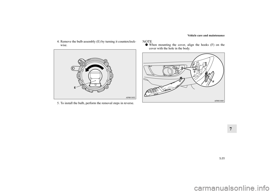
4. Remove the bulb assembly (E) by turning it counterclock-
wise.
5. To install the bulb, perform the removal steps in reverse.
NOTE�
When mounting the cover, align the hooks (F) on the
cover with the hole in the body.
BK0103001US.book 77 ページ 2009年8月20日 木曜日 午前10時45分

N00901900047
1. When replacing the bulb on the front passenger’s")
 counterclockwise to remove it. 4. While holding down the tab (D), pull out the bulb (E).
5. To install the bulb, perform the removal steps in r")
 counterclockwise to remove it. 3. Turn the socket (C) counterclockwise to remove it.*- Front of the vehicle
*- Front of the vehicle
BK0103001US.")

 counterclockwise to remove it. 4. Pull the bulb out of the socket.
5. To install the bulb, perform the removal steps in reverse.*- Front of t")
 counterclockwise to remove it.
4. Pull the bulb out of the socket.5. To install the bulb, perform the removal steps in reverse.
BK0103001US.b")
 by turn-
ing it counterclockwise.3. Remove the bulb by pulling it out.
4. To install the bulb, perform the removal")