2010 MERCEDES-BENZ GLK350 4MATIC light
[x] Cancel search: lightPage 196 of 344
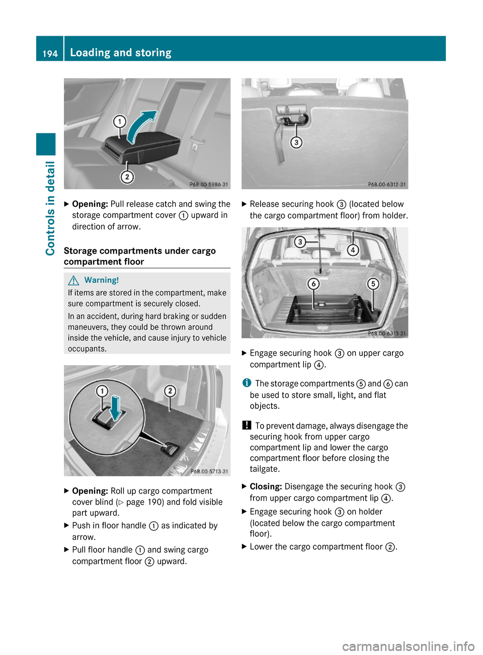
XOpening: Pull release catch and swing the
storage compartment cover : upward in
direction of arrow.
Storage compartments under cargo
compartment floor
GWarning!
If items are stored in the compartment, make
sure compartment is securely closed.
In an accident, during hard braking or sudden
maneuvers, they could be thrown around
inside the vehicle, and cause injury to vehicle
occupants.
XOpening: Roll up cargo compartment
cover blind (Y page 190) and fold visible
part upward.
XPush in floor handle : as indicated by
arrow.
XPull floor handle : and swing cargo
compartment floor ; upward.
XRelease securing hook = (located below
the cargo compartment floor) from holder.
XEngage securing hook = on upper cargo
compartment lip ?.
iThe storage compartments A and B can
be used to store small, light, and flat
objects.
! To prevent damage, always disengage the
securing hook from upper cargo
compartment lip and lower the cargo
compartment floor before closing the
tailgate.
XClosing: Disengage the securing hook =
from upper cargo compartment lip ?.
XEngage securing hook = on holder
(located below the cargo compartment
floor).
XLower the cargo compartment floor ;.194Loading and storingControls in detail
X204_AKB; 3; 23, en-USd2ureepe,Version: 2.11.8.12009-07-16T19:16:58+02:00 - Seite 194
Page 199 of 344
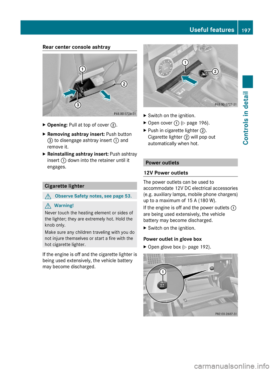
Rear center console ashtray XOpening: Pull at top of cover ;.XRemoving ashtray insert: Push button
= to disengage ashtray insert : and
remove it.
XReinstalling ashtray insert: Push ashtray
insert : down into the retainer until it
engages.
Cigarette lighter
GObserve Safety notes, see page 53.GWarning!
Never touch the heating element or sides of
the lighter; they are extremely hot. Hold the
knob only.
Make sure any children traveling with you do
not injure themselves or start a fire with the
hot cigarette lighter.
If the engine is off and the cigarette lighter is
being used extensively, the vehicle battery
may become discharged.
XSwitch on the ignition.XOpen cover : (Y page 196).XPush in cigarette lighter ;.
Cigarette lighter ; will pop out
automatically when hot.
Power outlets
12V Power outlets
The power outlets can be used to
accommodate 12V DC electrical accessories
(e.g. auxiliary lamps, mobile phone chargers)
up to a maximum of 15 A (180 W).
If the engine is off and the power outlets :
are being used extensively, the vehicle
battery may become discharged.
XSwitch on the ignition.
Power outlet in glove box
XOpen glove box (Y page 192).Useful features197Controls in detailX204_AKB; 3; 23, en-USd2ureepe,Version: 2.11.8.12009-07-16T19:16:58+02:00 - Seite 197Z
Page 208 of 344
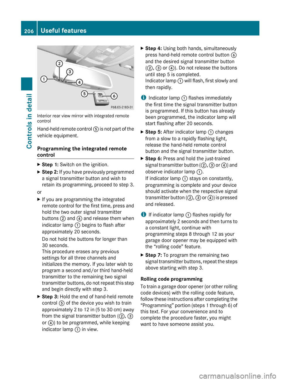
Interior rear view mirror with integrated remotecontrol
Hand-held remote control A is not part of the
vehicle equipment.
Programming the integrated remote
control
XStep 1: Switch on the ignition.XStep 2: If you have previously programmed
a signal transmitter button and wish to
retain its programming, proceed to step 3.
or
XIf you are programming the integrated
remote control for the first time, press and
hold the two outer signal transmitter
buttons ; and ? and release them when
indicator lamp : begins to flash after
approximately 20 seconds.
Do not hold the buttons for longer than
30 seconds.
This procedure erases any previous
settings for all three channels and
initializes the memory. If you later wish to
program a second and/or third hand-held
transmitter to the remaining two signal
transmitter buttons, do not repeat this step
and begin directly with step 3.
XStep 3: Hold the end of hand-held remote
control A of the device you wish to train
approximately 2 to 12 in (5 to 30 cm) away
from the signal transmitter button (;, =
or ?) to be programmed, while keeping
indicator lamp : in view.
XStep 4: Using both hands, simultaneously
press hand-held remote control button B
and the desired signal transmitter button
(;, = or ?). Do not release the buttons
until step 5 is completed.
Indicator lamp : will flash, first slowly and
then rapidly.
iIndicator lamp : flashes immediately
the first time the signal transmitter button
is programmed. If this button has already
been programmed, the indicator lamp will
start flashing after 20 seconds.
XStep 5: After indicator lamp : changes
from a slow to a rapidly flashing light,
release the hand-held remote control
button and the signal transmitter button.
XStep 6: Press and hold the just-trained
signal transmitter button (;, = or ?) and
observe indicator lamp :.
If indicator lamp : stays on constantly,
programming is complete and your device
should activate when the respective signal
transmitter button (;, = or ?) is pressed
and released.
iIf indicator lamp : flashes rapidly for
approximately 2 seconds and then turns to
a constant light, continue with
programming steps 8 through 12 as your
garage door opener may be equipped with
the “rolling code” feature.
XStep 7: To program the remaining two
signal transmitter buttons, repeat the steps
above starting with step 3.
Rolling code programming
To train a garage door opener (or other rolling
code devices) with the rolling code feature,
follow these instructions after completing the
“Programming” portion (steps 1 through 6) of
this text. For your convenience and to
complete the procedure faster, you might
want to have someone assist you.
206Useful featuresControls in detail
X204_AKB; 3; 23, en-USd2ureepe,Version: 2.11.8.12009-07-16T19:16:58+02:00 - Seite 206
Page 209 of 344
XStep 8: Locate the “training” button on the
garage door opener motor head unit.
i Exact location and color of the button may
vary by garage door opener brand.
Depending on manufacturer, the “training”
button may also be referred to as “learn” or
“smart” button. If there is difficulty locating
the transmitting button, refer to the garage
door opener Operator’s Manual.
XStep 9: Press the “training” button on the
garage door opener motor head unit.
The “training light” is activated.
You have 30 seconds to initiate the
following two steps.XStep 10: Return to the vehicle and firmly
press, hold for 2 seconds and release the
programmed signal transmitter button ( ;,
= or ?).XStep 11: Press, hold for 2 seconds and
release same signal transmitter button a
second time to complete the training
process.
i Some garage door openers (or other
rolling code equipped devices) may require
you to press, hold for 2 seconds and
release the same signal transmitter button
a third time to complete the training
process.
XStep 12: Confirm the garage door
operation by pressing the programmed
signal transmitter button ( ;, = or ?).XStep 13: To program the remaining two
signal transmitter buttons, repeat the steps
above starting with step 3.
Gate operator/Canadian programming
Canadian radio-frequency laws require
transmitter signals to “time-out” (or quit)
after several seconds of transmission which
may not be long enough for the integrated
signal transmitter to pick up the signal during
programming. Similar to this Canadian law,
some U.S. gate operators are designed to
“time-out” in the same manner.
If you live in Canada or if you are having
difficulties programming a gate operator
(regardless of where you live) by using the
programming procedures, replace step 4 with
the following:XStep 4: Press and hold the signal
transmitter button ( ;, = or ?). Do not
release this button until it has been
successfully trained.XWhile still holding down the signal
transmitter button ( ;, = or ?), “cycle”
your hand-held remote control button B
as follows: Press and hold button B for
2 seconds, then release it for 2 seconds,
and again press and hold it for 2 seconds.
Repeat this sequence on the hand-held
remote control until the frequency signal
has been learned.
Upon successful training, indicator
lamp : will flash slowly and then rapidly
after several seconds.XProceed with programming step 5 and
step 6 to complete.
i Upon completion of programming the
integrated remote control, make sure you
retain the hand-held remote control that
came with the garage door opener, gate
operator or other device. You may need it
for use in other vehicles, for future
programming of an integrated remote
control, or simply for continued use as a
hand-held remote control to operate the
respective device in other situations.
Reprogramming a single signal
transmitter button
To program a device using a signal
transmitter button previously trained, follow
these steps:
Useful features207Controls in detailX204_AKB; 3; 23, en-USd2ureepe,Version: 2.11.8.12009-07-16T19:16:58+02:00 - Seite 207Z
Page 215 of 344
Any noticeable irregularities in engine
operation should be repaired promptly.
Otherwise, excessive unburned fuel may
reach the catalytic converter, causing it to
overheat and potentially start a fire.
i Only use premium unleaded gasoline with
a minimum Posted Octane Rating of 91
(average of 96 RON/86 MON).
Information on gasoline quality can
normally be found on the fuel pump. Please
contact gas station personnel in case
labels on the pump cannot be found.
Locking/unlocking the vehicle with the
SmartKey or KEYLESS-GO automatically
locks/unlocks the fuel filler flap.
iIn case the central locking system does
not release the fuel filler flap, see “Fuel filler
flap” (Y page 301).
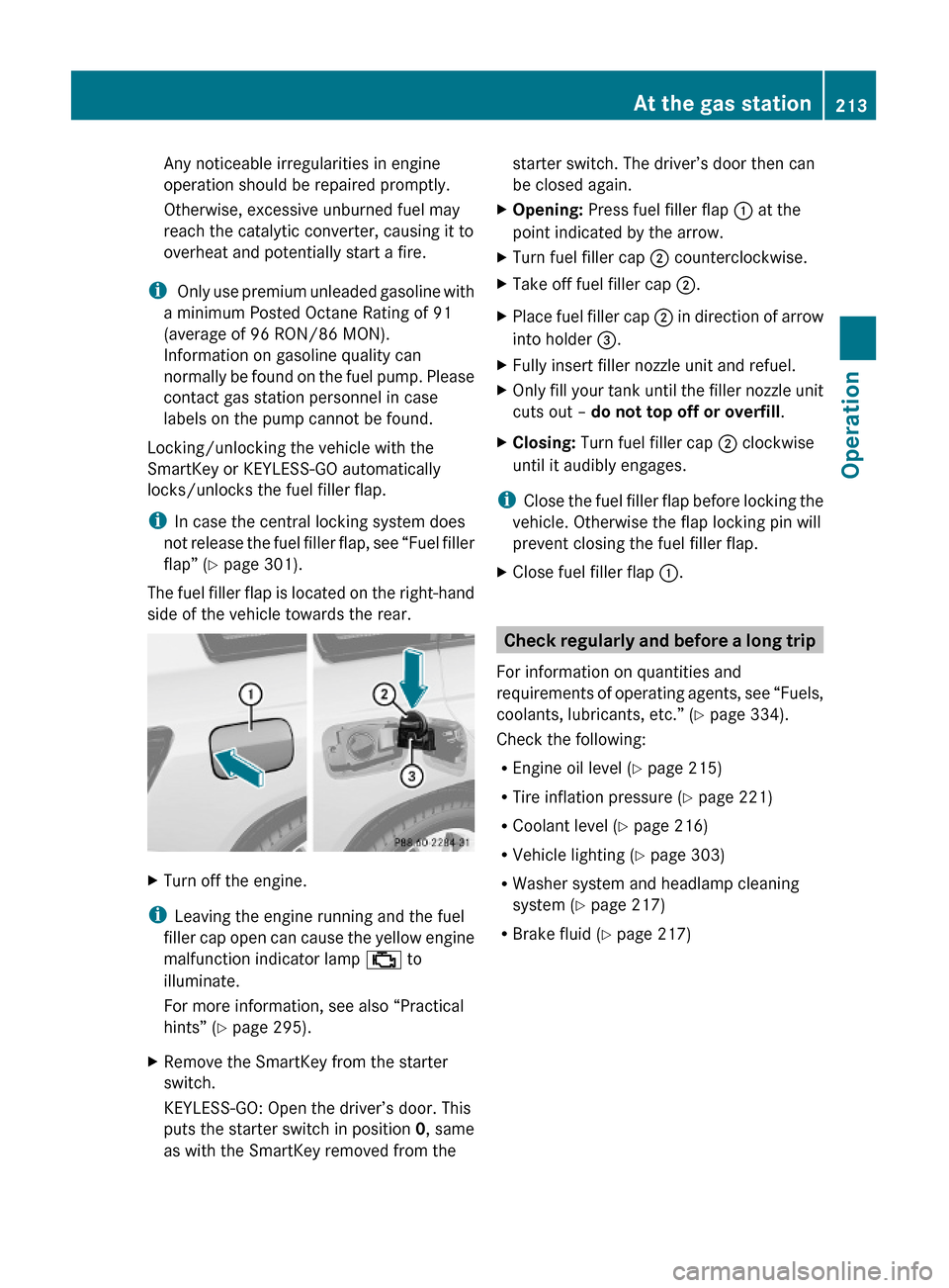
The fuel filler flap is located on the right-hand
side of the vehicle towards the rear.
XTurn off the engine.
iLeaving the engine running and the fuel
filler cap open can cause the yellow engine
malfunction indicator lamp ; to
illuminate.
For more information, see also “Practical
hints” (Y page 295).
XRemove the SmartKey from the starter
switch.
KEYLESS-GO: Open the driver’s door. This
puts the starter switch in position 0, same
as with the SmartKey removed from the
starter switch. The driver’s door then can
be closed again.
XOpening: Press fuel filler flap : at the
point indicated by the arrow.
XTurn fuel filler cap ; counterclockwise.XTake off fuel filler cap ;.XPlace fuel filler cap ; in direction of arrow
into holder =.
XFully insert filler nozzle unit and refuel.XOnly fill your tank until the filler nozzle unit
cuts out – do not top off or overfill.
XClosing: Turn fuel filler cap ; clockwise
until it audibly engages.
iClose the fuel filler flap before locking the
vehicle. Otherwise the flap locking pin will
prevent closing the fuel filler flap.
XClose fuel filler flap :.
Check regularly and before a long trip
For information on quantities and
requirements of operating agents, see “Fuels,
coolants, lubricants, etc.” (Y page 334).
Check the following:
REngine oil level (Y page 215)
RTire inflation pressure (Y page 221)
RCoolant level (Y page 216)
RVehicle lighting (Y page 303)
RWasher system and headlamp cleaning
system (Y page 217)
RBrake fluid (Y page 217)
At the gas station213OperationX204_AKB; 3; 23, en-USd2ureepe,Version: 2.11.8.12009-07-16T19:16:58+02:00 - Seite 213Z
Page 235 of 344
Storing tires
! Keep unmounted tires in a cool, dry place
with as little exposure to light as possible.
Protect tires from contact with oil, grease
and fuels.
Cleaning tires
! Never use a round nozzle to power wash
tires. The intense jet of water can result in
damage to the tire.
Always replace a damaged tire.
Uniform Tire Quality Grading
Standards
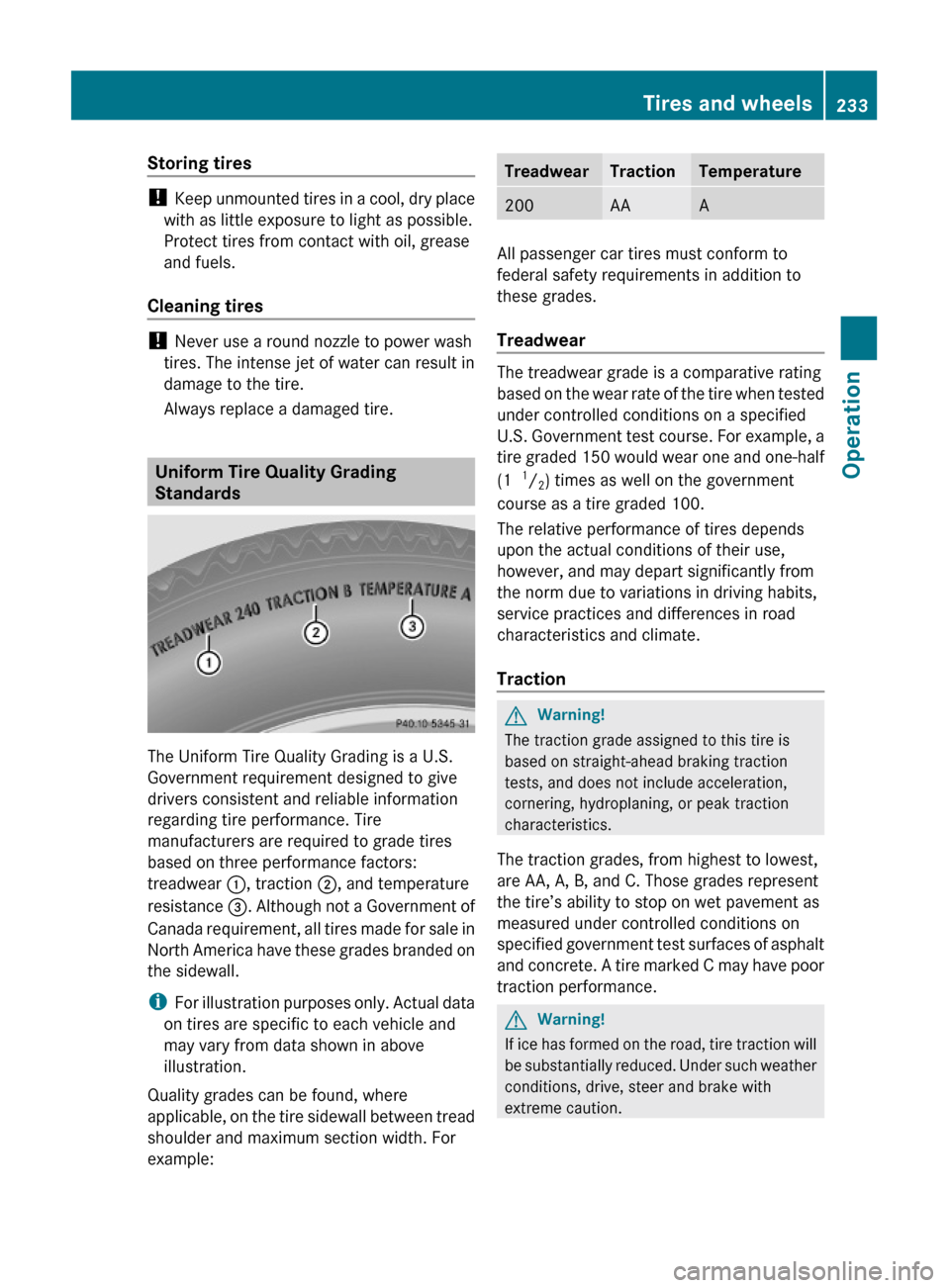
The Uniform Tire Quality Grading is a U.S.
Government requirement designed to give
drivers consistent and reliable information
regarding tire performance. Tire
manufacturers are required to grade tires
based on three performance factors:
treadwear :, traction ;, and temperature
resistance =. Although not a Government of
Canada requirement, all tires made for sale in
North America have these grades branded on
the sidewall.
iFor illustration purposes only. Actual data
on tires are specific to each vehicle and
may vary from data shown in above
illustration.
Quality grades can be found, where
applicable, on the tire sidewall between tread
shoulder and maximum section width. For
example:
TreadwearTractionTemperature200AAA
All passenger car tires must conform to
federal safety requirements in addition to
these grades.
Treadwear
The treadwear grade is a comparative rating
based on the wear rate of the tire when tested
under controlled conditions on a specified
U.S. Government test course. For example, a
tire graded 150 would wear one and one-half
(1 1/2) times as well on the government
course as a tire graded 100.
The relative performance of tires depends
upon the actual conditions of their use,
however, and may depart significantly from
the norm due to variations in driving habits,
service practices and differences in road
characteristics and climate.
Traction
GWarning!
The traction grade assigned to this tire is
based on straight-ahead braking traction
tests, and does not include acceleration,
cornering, hydroplaning, or peak traction
characteristics.
The traction grades, from highest to lowest,
are AA, A, B, and C. Those grades represent
the tire’s ability to stop on wet pavement as
measured under controlled conditions on
specified government test surfaces of asphalt
and concrete. A tire marked C may have poor
traction performance.
GWarning!
If ice has formed on the road, tire traction will
be substantially reduced. Under such weather
conditions, drive, steer and brake with
extreme caution.
Tires and wheels233OperationX204_AKB; 3; 23, en-USd2ureepe,Version: 2.11.8.12009-07-16T19:16:58+02:00 - Seite 233Z
Page 237 of 344
Thoroughly clean the mounting face of wheels
and brake disks, i.e. the inner side of the
wheels/tires, during each rotation. Check for
and ensure proper tire inflation pressure.
For information on wheel change, see “Flat
tire” (Y page 312).
Tire labeling
Besides tire name (sales designation) and
manufacturer name, a number of markings
can be found on a tire.
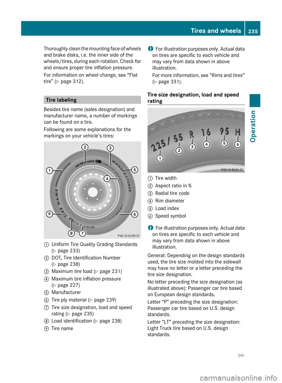
Following are some explanations for the
markings on your vehicle’s tires:
:Uniform Tire Quality Grading Standards
(Y page 233)
;DOT, Tire Identification Number
(Y page 238)
=Maximum tire load (Y page 231)?Maximum tire inflation pressure
(Y page 227)
AManufacturerBTire ply material (Y page 239)CTire size designation, load and speed
rating (Y page 235)
DLoad identification (Y page 238)ETire nameiFor illustration purposes only. Actual data
on tires are specific to each vehicle and
may vary from data shown in above
illustration.
For more information, see “Rims and tires”
(Y page 331).
Tire size designation, load and speed
rating
:Tire width;Aspect ratio in %=Radial tire code?Rim diameterALoad index BSpeed symbol
iFor illustration purposes only. Actual data
on tires are specific to each vehicle and
may vary from data shown in above
illustration.
General: Depending on the design standards
used, the tire size molded into the sidewall
may have no letter or a letter preceding the
tire size designation.
No letter preceding the size designation (as
illustrated above): Passenger car tire based
on European design standards.
Letter “P” preceding the size designation:
Passenger car tire based on U.S. design
standards.
Letter “LT” preceding the size designation:
Light Truck tire based on U.S. design
standards.
Tires and wheels235OperationX204_AKB; 3; 23, en-USd2ureepe,Version: 2.11.8.12009-07-16T19:16:58+02:00 - Seite 235Z
Page 240 of 344
Load identification
iFor illustration purposes only. Actual data
on tires are specific to each vehicle and
may vary from data shown in above
illustration.
In addition to the load index, special load
identification : may be molded into the tire
sidewall following the letter designating the
speed symbol B (Y page 235).
RNo specification given: absence of any text
(like in above example) indicates a
standard load (SL) tire.
RXL or Extra Load: designates an extra load
(or reinforced) tire.
RLight Load: designates a light load tire.
RC, D, E: designates load range associated
with the maximum load a tire can carry at
a specified pressure.
DOT, Tire Identification Number (TIN)
U.S. tire regulations require each new tire
manufacturer or tire retreader to mold a TIN
into or onto a sidewall of each tire produced.
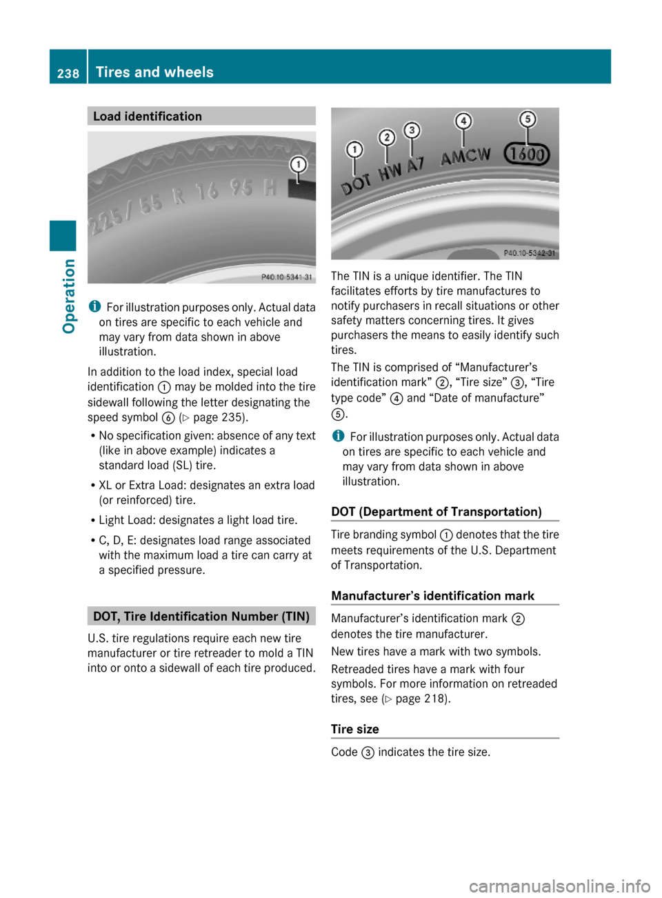
The TIN is a unique identifier. The TIN
facilitates efforts by tire manufactures to
notify purchasers in recall situations or other
safety matters concerning tires. It gives
purchasers the means to easily identify such
tires.
The TIN is comprised of “Manufacturer’s
identification mark” ;, “Tire size” =, “Tire
type code” ? and “Date of manufacture”
A.
iFor illustration purposes only. Actual data
on tires are specific to each vehicle and
may vary from data shown in above
illustration.
DOT (Department of Transportation)
Tire branding symbol : denotes that the tire
meets requirements of the U.S. Department
of Transportation.
Manufacturer’s identification mark
Manufacturer’s identification mark ;
denotes the tire manufacturer.
New tires have a mark with two symbols.
Retreaded tires have a mark with four
symbols. For more information on retreaded
tires, see (Y page 218).
Tire size
Code = indicates the tire size.
238Tires and wheelsOperation
X204_AKB; 3; 23, en-USd2ureepe,Version: 2.11.8.12009-07-16T19:16:58+02:00 - Seite 238