2010 MERCEDES-BENZ GLK350 4MATIC light
[x] Cancel search: lightPage 307 of 344
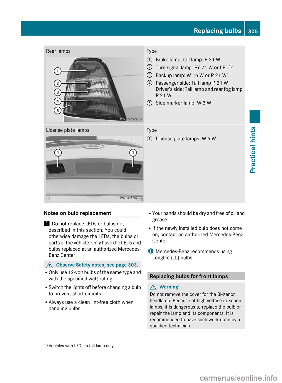
Rear lampsType:Brake lamp, tail lamp: P 21 W;Turn signal lamp: PY 21 W or LED13=Backup lamp: W 16 W or P 21 W13?Passenger side: Tail lamp P 21 W
Driver’s side: Tail lamp and rear fog lamp
P 21 W
ASide marker lamp: W 3 WLicense plate lampsType:License plate lamps: W 5 WNotes on bulb replacement
! Do not replace LEDs or bulbs not
described in this section. You could
otherwise damage the LEDs, the bulbs or
parts of the vehicle. Only have the LEDs and
bulbs replaced at an authorized Mercedes-
Benz Center.
GObserve Safety notes, see page 303.
ROnly use 12-volt bulbs of the same type and
with the specified watt rating.
RSwitch the lights off before changing a bulb
to prevent short circuits.
RAlways use a clean lint-free cloth when
handling bulbs.
RYour hands should be dry and free of oil and
grease.
RIf the newly installed bulb does not come
on, contact an authorized Mercedes-Benz
Center.
iMercedes-Benz recommends using
Longlife (LL) bulbs.
Replacing bulbs for front lamps
GWarning!
Do not remove the cover for the Bi-Xenon
headlamp. Because of high voltage in Xenon
lamps, it is dangerous to replace the bulb or
repair the lamp and its components. It is
recommended to have such work done by a
qualified technician.
13Vehicles with LEDs in tail lamp only.Replacing bulbs305Practical hintsX204_AKB; 3; 23, en-USd2ureepe,Version: 2.11.8.12009-07-16T19:16:58+02:00 - Seite 305Z
Page 310 of 344
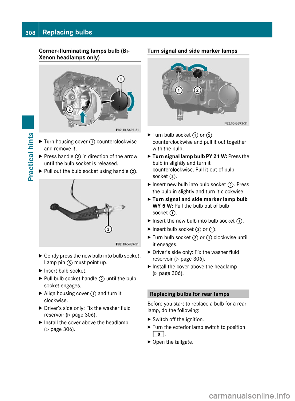
Corner-illuminating lamps bulb (Bi-
Xenon headlamps only)
XTurn housing cover : counterclockwise
and remove it.
XPress handle ; in direction of the arrow
until the bulb socket is released.
XPull out the bulb socket using handle ;.XGently press the new bulb into bulb socket.
Lamp pin = must point up.
XInsert bulb socket.XPull bulb socket handle ; until the bulb
socket engages.
XAlign housing cover : and turn it
clockwise.
XDriver’s side only: Fix the washer fluid
reservoir (Y page 306).
XInstall the cover above the headlamp
(Y page 306).
Turn signal and side marker lampsXTurn bulb socket : or ;
counterclockwise and pull it out together
with the bulb.
XTurn signal lamp bulb PY 21 W: Press the
bulb in slightly and turn it
counterclockwise. Pull it out of bulb
socket ;.
XInsert new bulb into bulb socket ;. Press
the bulb in slightly and turn it clockwise.
XTurn signal and side marker lamp bulb
WY 5 W: Pull the bulb out of bulb
socket :.
XInsert the new bulb into bulb socket :.XInsert bulb socket ; or :.XTurn bulb socket ; or : clockwise until
it engages.
XDriver’s side only: Fix the washer fluid
reservoir (Y page 306).
XInstall the cover above the headlamp
(Y page 306).
Replacing bulbs for rear lamps
Before you start to replace a bulb for a rear
lamp, do the following:
XSwitch off the ignition.XTurn the exterior lamp switch to position
$.
XOpen the tailgate.308Replacing bulbsPractical hints
X204_AKB; 3; 23, en-USd2ureepe,Version: 2.11.8.12009-07-16T19:16:58+02:00 - Seite 308
Page 315 of 344
Rreversible ratchet
R vehicle tool kit box
R electric air pump
For information on where to find the
respective items, see “Where will I find ...?”
( Y page 260) and ( Y page 262).
i Vehicles without spare wheel are not
factory-equipped with the tools required for
a wheel change such as a jack or a wheel
wrench. Some tools required for a wheel
change are specific to your vehicle.
Contact an authorized Mercedes-Benz
Center to obtain the tools approved for
your vehicle. This section describes the
wheel change using the tools approved and
recommended for your vehicle.
Lifting the vehicle
GWarning!
When jacking up the vehicle, only use the jack
which has been specifically approved by
Mercedes-Benz for your vehicle.
The jack is designed exclusively for jacking up
the vehicle at the jack take-up brackets built
into both sides of the vehicle. Make sure the
jack arm is fully seated in the jack take-up
bracket. The jack must always be vertical
when in use, especially on inclines or
declines.
The jack is intended only for lifting the vehicle
briefly for wheel changes. It is not suited for
performing maintenance work under the
vehicle. To help avoid personal injury, use the
jack only to lift the vehicle during a wheel
change.
Never get beneath the vehicle while it is
supported by the jack. Keep hands and feet
away from the area under the lifted vehicle.
Always lower the vehicle onto sufficient
capacity jackstands before working under the
vehicle.
Always engage the parking brake firmly and
block the wheels with wheel chocks or other
sizeable objects before raising the vehicle
with the jack. Do not disengage the parking
brake while the vehicle is raised.
Make sure that the ground on which the
vehicle is standing and where you place the
jack is solid, level and not slippery. If
necessary, use a large underlay. On slippery
surfaces, such as tiled floors, you should use
a non-slip underlay, for example a rubber mat.
Do not use wooden blocks or similar objects
to support the jack. Otherwise the jack may
not be able to achieve its load-bearing
capacity if it is not at its full height.
Never start the engine when the vehicle is
raised.
Also observe the notes on the jack.XPrevent the vehicle from rolling away by
blocking wheels with wheel chocks or other
sizeable objects.
When your vehicle is equipped with a wheel
chock, it is included with the vehicle tool kit
( Y page 260). For information on setting up
the collapsible wheel chock, see
( Y page 261).
When changing a wheel on a level surface:
XPlace a wheel chock or other sizeable
object in front of and another wheel chock
or other sizeable object behind the wheel
that is diagonally opposite to the wheel
being changed.
Always try lifting the vehicle using the jack on
a level surface. However, should
circumstances require you to do so on a hill:
XPlace wheel chocks or other sizeable
objects on the downhill side in front of both
wheels on the side opposite to the side on
which the wheel is to be changed.GWarning!
Only jack up the vehicle on level ground or on
slight inclines/declines. Otherwise, the
vehicle could fall off the jack and injure you or
others.
Flat tire313Practical hintsX204_AKB; 3; 23, en-USd2ureepe,Version: 2.11.8.12009-07-16T19:16:58+02:00 - Seite 313Z
Page 317 of 344
Never apply oil or grease to wheel bolts.
Damaged wheel hub threads should be
repaired immediately. Do not continue to
drive under these circumstances! Contact an
authorized Mercedes-Benz Center or call
Roadside Assistance.
Incorrect wheel bolts or improperly tightened
wheel bolts can cause the wheel to come off.
This could cause an accident. Make sure to
use the correct wheel bolts.
GWarning!
Only use genuine Mercedes-Benz wheel bolts.
Other wheel bolts may come loose.
Do not tighten the wheel bolts when the
vehicle is raised. Otherwise the vehicle could
fall off the jack.
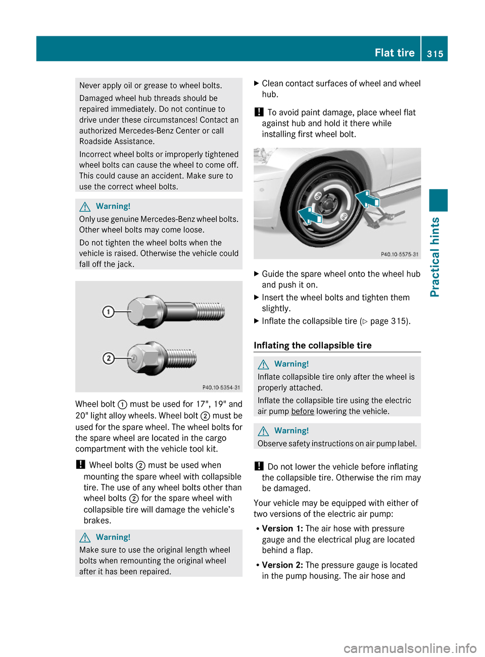
Wheel bolt : must be used for 17", 19" and
20" light alloy wheels. Wheel bolt ; must be
used for the spare wheel. The wheel bolts for
the spare wheel are located in the cargo
compartment with the vehicle tool kit.
! Wheel bolts ; must be used when
mounting the spare wheel with collapsible
tire. The use of any wheel bolts other than
wheel bolts ; for the spare wheel with
collapsible tire will damage the vehicle’s
brakes.
GWarning!
Make sure to use the original length wheel
bolts when remounting the original wheel
after it has been repaired.
XClean contact surfaces of wheel and wheel
hub.
! To avoid paint damage, place wheel flat
against hub and hold it there while
installing first wheel bolt.
XGuide the spare wheel onto the wheel hub
and push it on.
XInsert the wheel bolts and tighten them
slightly.
XInflate the collapsible tire (Y page 315).
Inflating the collapsible tire
GWarning!
Inflate collapsible tire only after the wheel is
properly attached.
Inflate the collapsible tire using the electric
air pump before lowering the vehicle.
GWarning!
Observe safety instructions on air pump label.
! Do not lower the vehicle before inflating
the collapsible tire. Otherwise the rim may
be damaged.
Your vehicle may be equipped with either of
two versions of the electric air pump:
RVersion 1: The air hose with pressure
gauge and the electrical plug are located
behind a flap.
RVersion 2: The pressure gauge is located
in the pump housing. The air hose and
Flat tire315Practical hintsX204_AKB; 3; 23, en-USd2ureepe,Version: 2.11.8.12009-07-16T19:16:58+02:00 - Seite 315Z
Page 318 of 344
electrical plug are located at the bottom of
the pump housing.
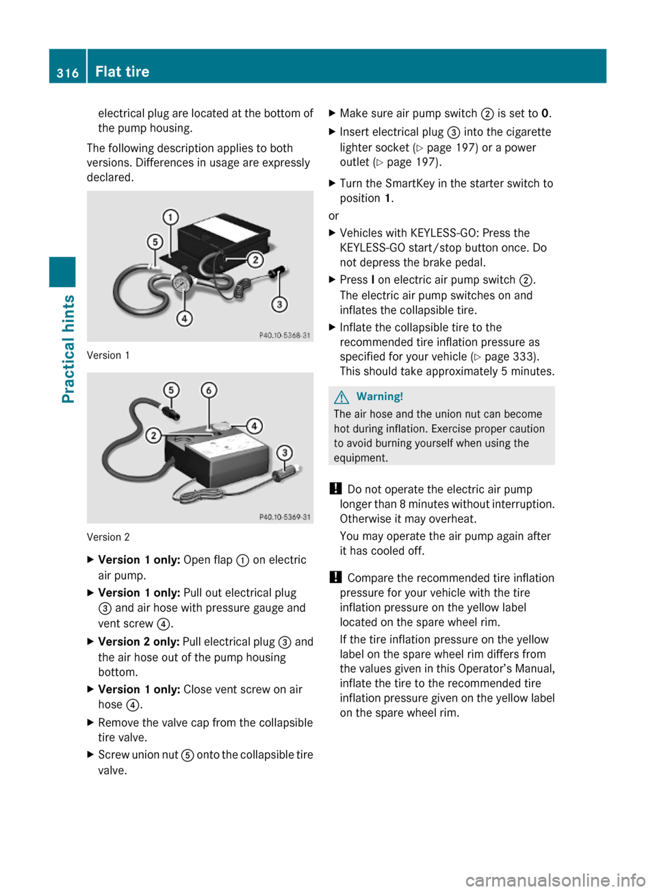
The following description applies to both
versions. Differences in usage are expressly
declared.
Version 1
Version 2
XVersion 1 only: Open flap : on electric
air pump.
XVersion 1 only: Pull out electrical plug
= and air hose with pressure gauge and
vent screw ?.
XVersion 2 only: Pull electrical plug = and
the air hose out of the pump housing
bottom.
XVersion 1 only: Close vent screw on air
hose ?.
XRemove the valve cap from the collapsible
tire valve.
XScrew union nut A onto the collapsible tire
valve.
XMake sure air pump switch ; is set to 0.XInsert electrical plug = into the cigarette
lighter socket (Y page 197) or a power
outlet (Y page 197).
XTurn the SmartKey in the starter switch to
position 1.
or
XVehicles with KEYLESS-GO: Press the
KEYLESS-GO start/stop button once. Do
not depress the brake pedal.
XPress I on electric air pump switch ;.
The electric air pump switches on and
inflates the collapsible tire.
XInflate the collapsible tire to the
recommended tire inflation pressure as
specified for your vehicle (Y page 333).
This should take approximately 5 minutes.
GWarning!
The air hose and the union nut can become
hot during inflation. Exercise proper caution
to avoid burning yourself when using the
equipment.
! Do not operate the electric air pump
longer than 8 minutes without interruption.
Otherwise it may overheat.
You may operate the air pump again after
it has cooled off.
! Compare the recommended tire inflation
pressure for your vehicle with the tire
inflation pressure on the yellow label
located on the spare wheel rim.
If the tire inflation pressure on the yellow
label on the spare wheel rim differs from
the values given in this Operator’s Manual,
inflate the tire to the recommended tire
inflation pressure given on the yellow label
on the spare wheel rim.
316Flat tirePractical hints
X204_AKB; 3; 23, en-USd2ureepe,Version: 2.11.8.12009-07-16T19:16:58+02:00 - Seite 316
Page 335 of 344
Same size tiresModelGLK 35022
GLK 350 4MATIC17" wheelsRims (light alloy)
Wheel offset7.5 J x 17 H2
1.87 in (47.5 mm)Winter tires 23,24235/60 R17 102H M+S
i19" wheelsRims (light alloy)
Wheel offset7.5 J x 19 H2
1.85 in (47 mm)All-season tires 23235/50 R19 99H M+S20" wheelsRims (light alloy)
Wheel offset8.5 J x 20 H2
1.77 in (45 mm)All-season tires 23235/45 R20 100H XL (Extra Load) M+S
Spare wheel
! Compare the recommended tire inflation pressure for your vehicle with the tire inflation
pressure on the yellow label located on the spare wheel rim.
If the tire inflation pressure on the yellow label on the spare wheel rim differs from the values
given in this Operator’s Manual, inflate the tire to the recommended tire inflation pressure
given on the yellow label on the spare wheel rim.
i Please note that the tire inflation pressure of the spare wheel differs from the tire inflation
pressure of the road tires.
ModelAll modelsRim (light alloy)6 B x 17 H2Wheel offset0.98 in (25 mm)Collapsible tire 25185/75-17 98PRecommended tire inflation pressure41 psi (2.8 bar)22
USA only.
23 Radial-ply tires.
24 Not available as factory equipment.
25 Must not be used with snow chains.Rims and tires333Technical dataX204_AKB; 3; 23, en-USd2ureepe,Version: 2.11.8.12009-07-16T19:16:58+02:00 - Seite 333Z
Page 338 of 344
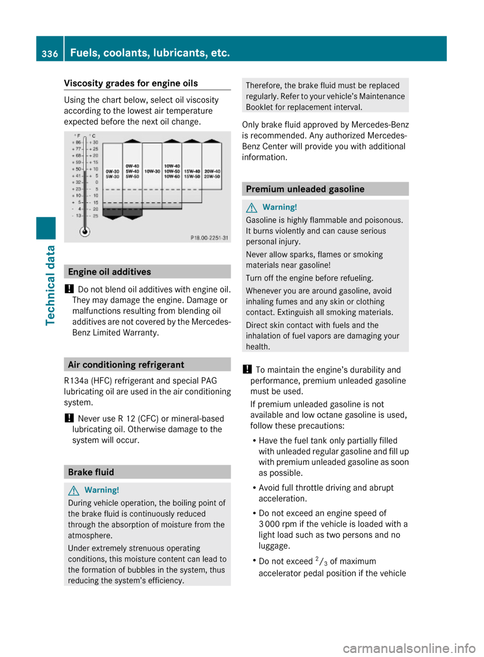
Viscosity grades for engine oils
Using the chart below, select oil viscosity
according to the lowest air temperature
expected before the next oil change.
Engine oil additives
! Do not blend oil additives with engine oil.
They may damage the engine. Damage or
malfunctions resulting from blending oil
additives are not covered by the Mercedes-
Benz Limited Warranty.
Air conditioning refrigerant
R134a (HFC) refrigerant and special PAG
lubricating oil are used in the air conditioning
system.
! Never use R 12 (CFC) or mineral-based
lubricating oil. Otherwise damage to the
system will occur.
Brake fluid
GWarning!
During vehicle operation, the boiling point of
the brake fluid is continuously reduced
through the absorption of moisture from the
atmosphere.
Under extremely strenuous operating
conditions, this moisture content can lead to
the formation of bubbles in the system, thus
reducing the system’s efficiency.
Therefore, the brake fluid must be replaced
regularly. Refer to your vehicle’s Maintenance
Booklet for replacement interval.
Only brake fluid approved by Mercedes-Benz
is recommended. Any authorized Mercedes-
Benz Center will provide you with additional
information.
Premium unleaded gasoline
GWarning!
Gasoline is highly flammable and poisonous.
It burns violently and can cause serious
personal injury.
Never allow sparks, flames or smoking
materials near gasoline!
Turn off the engine before refueling.
Whenever you are around gasoline, avoid
inhaling fumes and any skin or clothing
contact. Extinguish all smoking materials.
Direct skin contact with fuels and the
inhalation of fuel vapors are damaging your
health.
! To maintain the engine’s durability and
performance, premium unleaded gasoline
must be used.
If premium unleaded gasoline is not
available and low octane gasoline is used,
follow these precautions:
RHave the fuel tank only partially filled
with unleaded regular gasoline and fill up
with premium unleaded gasoline as soon
as possible.
RAvoid full throttle driving and abrupt
acceleration.
RDo not exceed an engine speed of
3 000 rpm if the vehicle is loaded with a
light load such as two persons and no
luggage.
RDo not exceed 2/3 of maximum
accelerator pedal position if the vehicle
336Fuels, coolants, lubricants, etc.Technical data
X204_AKB; 3; 23, en-USd2ureepe,Version: 2.11.8.12009-07-16T19:16:58+02:00 - Seite 336