2010 MERCEDES-BENZ GLK350 4MATIC instrument cluster
[x] Cancel search: instrument clusterPage 112 of 344
Outside temperature indicator
The outside temperature indicator is
displayed in the multifunction display
(Y page 112).
GWarning!
The outside temperature indicator is not
designed to serve as an ice-warning device
and is therefore unsuitable for that purpose.
Indicated temperatures just above the
freezing point do not guarantee that the road
surface is free of ice. The road may still be icy,
especially in wooded areas or on bridges.
Fuel gauge
The fuel gauge is on the left-hand side of the
instrument cluster (Y page 28). Once the fuel
level has fallen below the reserve mark, the
yellow fuel tank reserve warning lamp 8
for the fuel reserve comes on.
Control system
Introduction
The control system is activated as soon as the
starter switch is in position 2.
The control system enables you to call up
information about your vehicle and to change
vehicle settings.
For example, you can use the control system
to find out when your vehicle is next due for
maintenance service, to call up statistical
data on your vehicle, and much more.
GWarning!
A driver’s attention to the road and traffic
conditions must always be his/her primary
focus when driving.
For your safety and the safety of others,
selecting features through the multifunction
steering wheel should only be done by the
driver when traffic and road conditions permit
it to be done safely.
Bear in mind that at a speed of just 30 mph
(approximately 50 km/h), your vehicle is
covering a distance of 44 feet (approximately
14 m) every second.
The control system relays information to the
multifunction display.
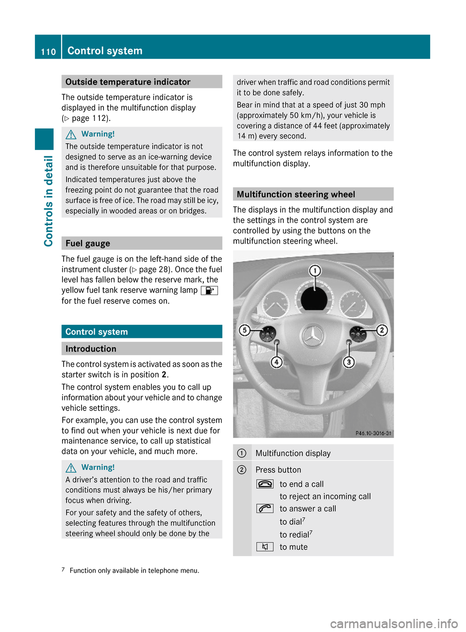
Multifunction steering wheel
The displays in the multifunction display and
the settings in the control system are
controlled by using the buttons on the
multifunction steering wheel.
:Multifunction display;Press button~to end a call
to reject an incoming call
6to answer a call
to dial7
to redial7
8to mute7Function only available in telephone menu.110Control systemControls in detail
X204_AKB; 3; 23, en-USd2ureepe,Version: 2.11.8.12009-07-16T19:16:58+02:00 - Seite 110
Page 122 of 344
XPress button : or 9 to select a
submenu.
Scroll down with button :, scroll up with
button 9.
With the selection marker on the desired
submenu, use the button a to access the
individual functions within that submenu.
Once within the submenu, you can use button
9 to move to the next function or
button : to move to the previous function
within that submenu.
The following lists show what settings can be
changed within the various menus. Detailed
instructions on making individual settings can
be found on the following pages.
Instrument cluster submenu
RSelecting speedometer display mode
(Y page 120)
RPermanent display (speed display or
outside temperature) (Y page 121)
Time/Date submenu
RSetting the time (Y page 121)
RSetting the date (Y page 121)
Lights submenu
RSwitching daytime running lamp mode on
or off (USA only) (Y page 122)
RSwitching locator lighting on or off
(Y page 122)
RSwitching interior lighting delayed shut-off
on or off (Y page 123)
Vehicle submenu
RSwitching automatic central locking on or
off (Y page 124)
Convenience submenu
RActivating easy-entry/exit feature
(Y page 124)
RSwitching fold-in function for exterior rear
view mirrors on or off (Y page 124)
Instrument cluster submenu
Access the Instr. Cluster submenu via
the Settings menu. Use the Instr.
Cluster submenu to change the instrument
cluster display settings.
The following functions are available:
RSelecting speedometer display mode
(Y page 120)
RPermanent display (speed display or
outside temperature) (Y page 121)
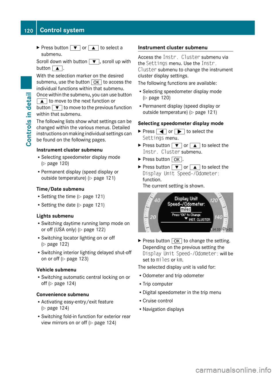
Selecting speedometer display mode
XPress = or ; to select the
Settings menu.
XPress button : or 9 to select the
Instr. Cluster submenu.
XPress button a.XPress button : or 9 to select the
Display Unit Speed-/Odometer:
function.
The current setting is shown.
XPress button a to change the setting.
Depending on the previous setting the
Display Unit Speed-/Odometer: will be
set to miles or km.
The selected display unit is valid for:
ROdometer and trip odometer
RTrip computer
RDigital speedometer in the trip menu
RCruise control
RNavigation displays
120Control systemControls in detail
X204_AKB; 3; 23, en-USd2ureepe,Version: 2.11.8.12009-07-16T19:16:58+02:00 - Seite 120
Page 130 of 344
FTuning to a station via station search
(Y page 138)
Fast rewind (Y page 153)
Skipping backwards to a track
(Y page 153)
GConfirming a passcode
(Y page 159)
Accepting a call (Y page 167)
Initiating a call (Y page 165)
Redial (Y page 166)
HRejecting a call (Y page 167)
Ending an active call (Y page 167)
IOpening system settings menu
(Y page 135)
JSwitching sound on/off
(Y page 133)
Switching hands-free microphone
on/off (Y page 167)
KSwitching to telephone mode
(Y page 155)
LSound settings (Y page 133)
Audio display
! Avoid touching the audio display at all
times. The display has a very sensitive high-
gloss surface, there is a risk of it being
scratched. Do not press directly in the
display face. Otherwise, the audio display
will be damaged.
iFor information about cleaning and care
of the audio display, see “Audio or
COMAND display” (Y page 256).
Display
The currently selected mode and the
associated menus are shown on the audio
display. The audio display is divided into
several areas.
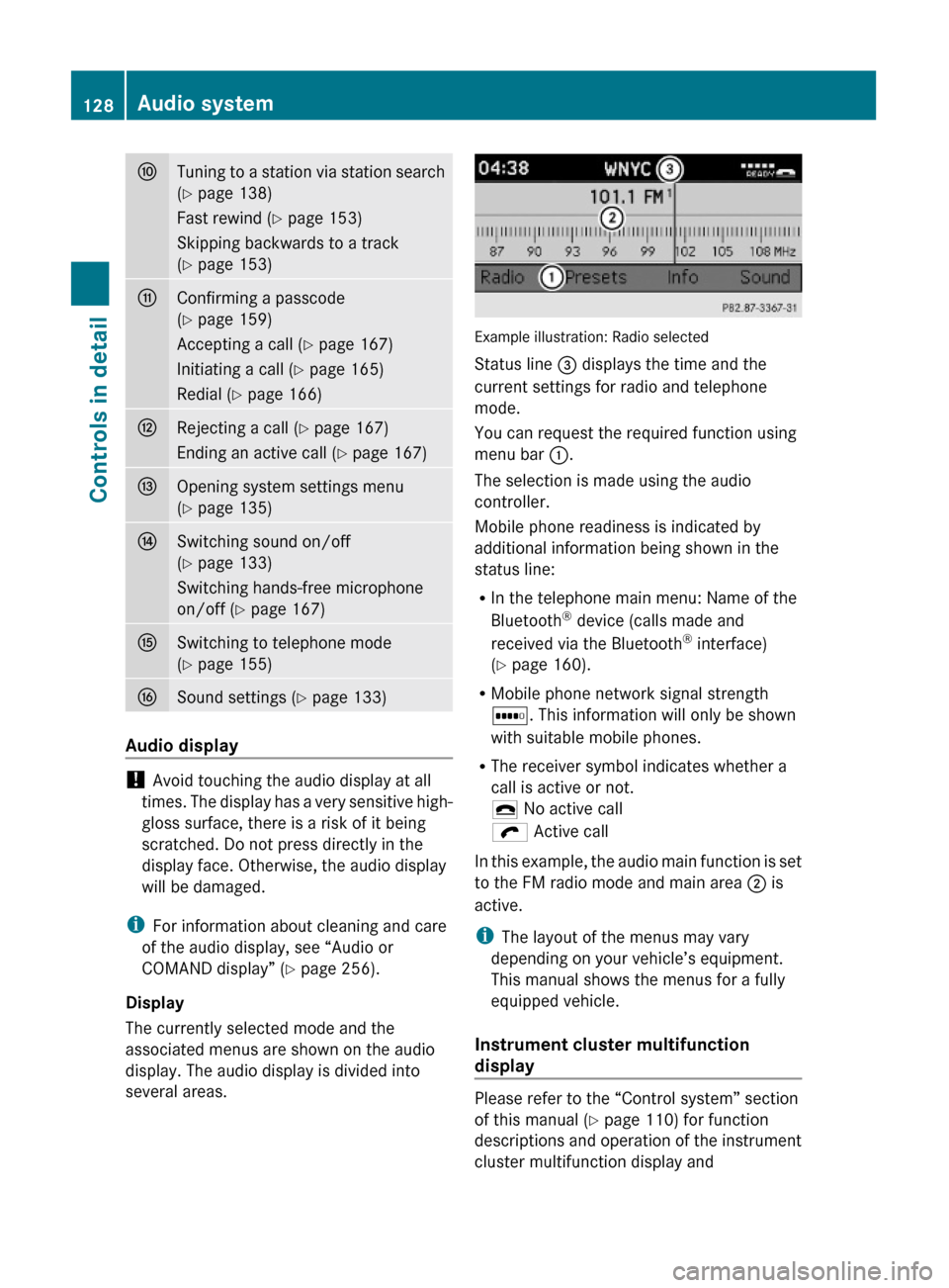
Example illustration: Radio selected
Status line = displays the time and the
current settings for radio and telephone
mode.
You can request the required function using
menu bar :.
The selection is made using the audio
controller.
Mobile phone readiness is indicated by
additional information being shown in the
status line:
RIn the telephone main menu: Name of the
Bluetooth® device (calls made and
received via the Bluetooth® interface)
(Y page 160).
RMobile phone network signal strength
r. This information will only be shown
with suitable mobile phones.
RThe receiver symbol indicates whether a
call is active or not.
¢ No active call
ö Active call
In this example, the audio main function is set
to the FM radio mode and main area ; is
active.
iThe layout of the menus may vary
depending on your vehicle’s equipment.
This manual shows the menus for a fully
equipped vehicle.
Instrument cluster multifunction
display
Please refer to the “Control system” section
of this manual (Y page 110) for function
descriptions and operation of the instrument
cluster multifunction display and
128Audio systemControls in detail
X204_AKB; 3; 23, en-USd2ureepe,Version: 2.11.8.12009-07-16T19:16:58+02:00 - Seite 128
Page 226 of 344
Advanced Tire Pressure Monitoring
System (Advanced TPMS), (USA only)
Your vehicle is equipped with the Advanced
Tire Pressure Monitoring System (Advanced
TPMS). It measures the tire inflation pressure
in the vehicle’s tires and issues warnings in
case of pressure loss in one or more of the
tires.
The TPMS is equipped with a combination low
tire pressure/ TPMS malfunction telltale in
the instrument cluster. Depending on how the
telltale illuminates, it indicates a low tire
pressure condition or a malfunction in the
TPMS system itself:
R If the telltale illuminates continuously, one
or more of your tires is significantly
underinflated. There is no malfunction in
the TPMS.
R If the telltale flashes for 60 seconds and
then stays illuminated, the TPMS system
itself is not operating properly.
The TPMS only functions on wheels that are
equipped with the proper electronic sensors.
GWarning!
The TPMS does not indicate a warning for
wrongly selected inflation pressures. Always
adjust tire inflation pressure according to the
Tire and Loading Information placard or the
supplemental tire inflation pressure
information on the inside of the fuel filler flap.
The TPMS is not able to issue a warning due
to a sudden dramatic loss of pressure (e.g. tire
blowout caused by a foreign object). In this
case bring the vehicle to a halt by carefully
applying the brakes and avoiding abrupt
steering maneuvers.
GWarning!
Each tire, including the spare (if provided),
should be checked at least once a month
when cold and inflated to the inflation
pressure recommended by the vehicle
manufacturer on the Tire and Loading
Information placard on the driver’s door B-
pillar or the tire inflation pressure label on the
inside of the fuel filler flap. If your vehicle has
tires of a different size than the size indicated
on the Tire and Loading Information placard
or the tire inflation pressure label, you should
determine the proper tire inflation pressure
for those tires.
As an added safety feature, your vehicle has
been equipped with a tire pressure monitoring
system (TPMS) that illuminates a low tire
pressure telltale when one or more of your
tires are significantly underinflated.
Accordingly, when the low tire pressure
telltale illuminates, you should stop and check
your tires as soon as possible, and inflate
them to the proper pressure. Driving on a
significantly underinflated tire causes the tire
to overheat and can lead to tire failure.
Underinflation also reduces fuel efficiency
and tire tread life, and may affect the vehicle’s
handling and stopping ability. Please note that
the TPMS is not a substitute for proper tire
maintenance, and it is the driver’s
responsibility to maintain correct tire
pressure, even if underinflation has not
reached the level to trigger illumination of the
TPMS low tire pressure telltale.
Your vehicle has also been equipped with a
TPMS malfunction indicator to indicate when
the system is not operating properly. The
TPMS malfunction indicator is combined with
the low tire pressure telltale. When the
system detects a malfunction, the telltale will
flash for approximately 1 minute and then
remain continuously illuminated. This
sequence will continue upon subsequent
vehicle start-ups as long as the malfunction
exists. When the malfunction indicator is
illuminated, the system may not be able to
detect or signal low tire pressure as intended.
TPMS malfunctions may occur for a variety of
reasons, including the installation of
incompatible replacement or alternate tires
or wheels on the vehicle that prevent the
TPMS from functioning properly. Always
check the TPMS malfunction telltale after224Tires and wheelsOperation
X204_AKB; 3; 23, en-USd2ureepe,Version: 2.11.8.12009-07-16T19:16:58+02:00 - Seite 224
Page 227 of 344
replacing one or more tires or wheels on your
vehicle to ensure that the replacement or
alternate tires and wheels allow the TPMS to
continue to function properly.
iIf a condition causing the TPMS to
malfunction develops, it may take up to
10 minutes for the system to signal a
malfunction using the TPMS telltale
flashing and illumination sequence.
The telltale extinguishes after a few
minutes driving if the malfunction has been
corrected.
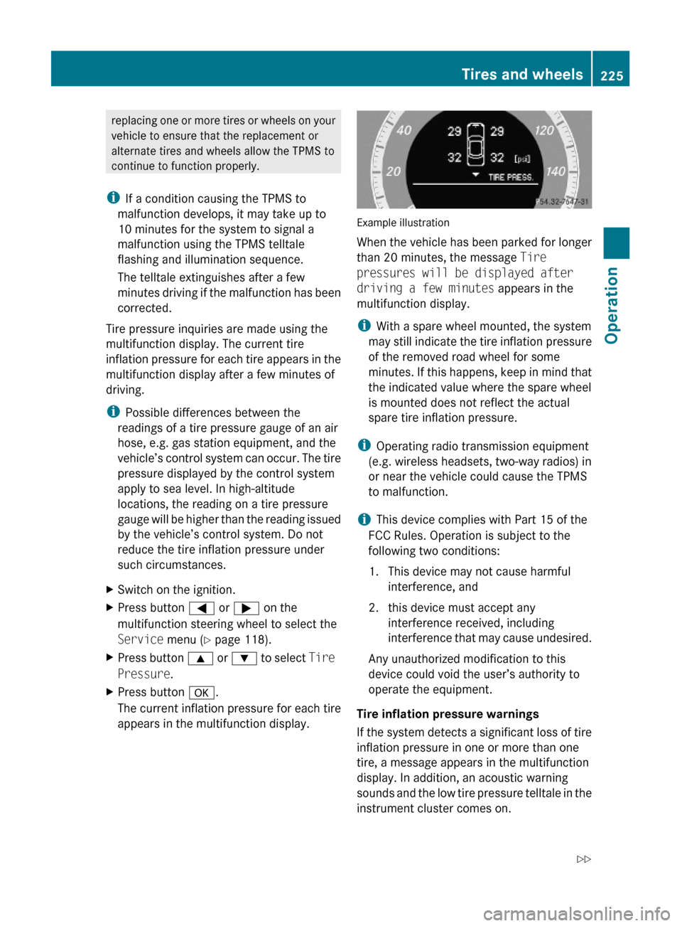
Tire pressure inquiries are made using the
multifunction display. The current tire
inflation pressure for each tire appears in the
multifunction display after a few minutes of
driving.
iPossible differences between the
readings of a tire pressure gauge of an air
hose, e.g. gas station equipment, and the
vehicle’s control system can occur. The tire
pressure displayed by the control system
apply to sea level. In high-altitude
locations, the reading on a tire pressure
gauge will be higher than the reading issued
by the vehicle’s control system. Do not
reduce the tire inflation pressure under
such circumstances.
XSwitch on the ignition.XPress button = or ; on the
multifunction steering wheel to select the
Service menu (Y page 118).
XPress button 9 or : to select Tire
Pressure.
XPress button a.
The current inflation pressure for each tire
appears in the multifunction display.
Example illustration
When the vehicle has been parked for longer
than 20 minutes, the message Tire
pressures will be displayed after
driving a few minutes appears in the
multifunction display.
iWith a spare wheel mounted, the system
may still indicate the tire inflation pressure
of the removed road wheel for some
minutes. If this happens, keep in mind that
the indicated value where the spare wheel
is mounted does not reflect the actual
spare tire inflation pressure.
iOperating radio transmission equipment
(e.g. wireless headsets, two-way radios) in
or near the vehicle could cause the TPMS
to malfunction.
iThis device complies with Part 15 of the
FCC Rules. Operation is subject to the
following two conditions:
1. This device may not cause harmful
interference, and
2. this device must accept any
interference received, including
interference that may cause undesired.
Any unauthorized modification to this
device could void the user’s authority to
operate the equipment.
Tire inflation pressure warnings
If the system detects a significant loss of tire
inflation pressure in one or more than one
tire, a message appears in the multifunction
display. In addition, an acoustic warning
sounds and the low tire pressure telltale in the
instrument cluster comes on.
Tires and wheels225OperationX204_AKB; 3; 23, en-USd2ureepe,Version: 2.11.8.12009-07-16T19:16:58+02:00 - Seite 225Z
Page 247 of 344
braking distance, which could lead to an
accident.
To avoid this danger, you should:
R occasionally brake carefully when you are
driving on salt-covered roads, so that any
layer of salt that may have built up on the
brake discs and the brake linings is
removed without putting other road users
at risk
R maintain a greater distance to the vehicle
ahead and drive with particular care
R carefully apply the brakes at the end of a
trip and immediately after commencing a
new trip, so that salt residues are removed
from the brake disc
Brake service
! The brake fluid level in the reservoir may
be too low if the red brake warning lamp in
the instrument cluster comes on while the
engine is running and an acoustic warning
sounds. Observe additional messages in
the multifunction display that may appear.
Brake pad wear or a leak in the system may
be the reason for low brake fluid in the
reservoir.
Have the brake system inspected
immediately. Contact an authorized
Mercedes-Benz Center.
All checks and service work on the brake
system should be carried out by qualified
technicians only. Contact an authorized
Mercedes-Benz Center.
Only install brake pads and use brake fluid
recommended by Mercedes-Benz.
GWarning!
If other than recommended brake pads are
installed, or other than recommended brake
fluid is used, the braking properties of the
vehicle can be degraded to an extent that safe
braking is substantially impaired. This could
result in an accident.
! Vehicles with 4MATIC:
Only conduct operational or performance
tests on a two-axle dynamometer. If such
tests are necessary, contact an authorized
Mercedes-Benz Center. You could
otherwise seriously damage the brake
system or the transfer case which is not
covered by the Mercedes-Benz Limited
Warranty.
! Because the ESP ®
operates
automatically, the engine and ignition must
be shut off (SmartKey in starter switch
position 0 or 1) when
R the parking brake is being tested on a
brake test dynamometer
R towing the vehicle with the front or rear
axle raised (not permissible for vehicles
with 4MATIC)
Active braking action through the ESP ®
may otherwise seriously damage the brake
system which is not covered by the
Mercedes-Benz Limited Warranty.
If your brake system is only subjected to
moderate loads, you should occasionally test
the effectiveness of the brakes by applying
above-normal braking pressure at higher
speeds. This will also enhance the grip of the
brake pads.GWarning!
Make sure not to endanger any other road
users when carrying out these braking
maneuvers.
Refer to the description of the Brake Assist
System (BAS) ( Y page 60).
Driving off
Warm up the engine smoothly. Do not place
full load on the engine until the operating
temperature has been reached.
! When driving off on a slippery surface, do
not allow a drive wheel to spin for an
Driving instructions245OperationX204_AKB; 3; 23, en-USd2ureepe,Version: 2.11.8.12009-07-16T19:16:58+02:00 - Seite 245Z
Page 264 of 344
XAttach reversible ratchet ; to jack : in
such a way that the word UP can be seen.
Before placing the jack and the reversible
ratchet back into the vehicle tool kit:
XFully collapse the jack (storage position).XRemove the reversible ratchet.
Spare wheel
GObserve Safety notes, see page 312.
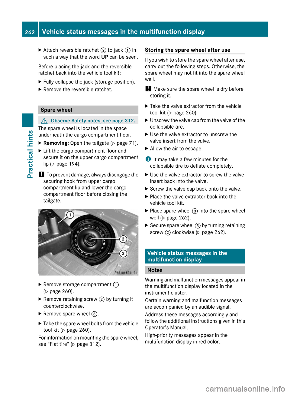
The spare wheel is located in the space
underneath the cargo compartment floor.
XRemoving: Open the tailgate (Y page 71).XLift the cargo compartment floor and
secure it on the upper cargo compartment
lip (Y page 194).
! To prevent damage, always disengage the
securing hook from upper cargo
compartment lip and lower the cargo
compartment floor before closing the
tailgate.
XRemove storage compartment :
(Y page 260).
XRemove retaining screw ; by turning it
counterclockwise.
XRemove spare wheel =.XTake the spare wheel bolts from the vehicle
tool kit (Y page 260).
For information on mounting the spare wheel,
see “Flat tire” (Y page 312).
Storing the spare wheel after use
If you wish to store the spare wheel after use,
carry out the following steps. Otherwise, the
spare wheel may not fit into the spare wheel
well.
! Make sure the spare wheel is dry before
storing it.
XTake the valve extractor from the vehicle
tool kit (Y page 260).
XUnscrew the valve cap from the valve of the
collapsible tire.
XUse the valve extractor to unscrew the
valve insert from the valve.
XAllow the air to escape.
iIt may take a few minutes for the
collapsible tire to deflate completely.
XUse the valve extractor to screw the valve
insert back into the valve.
XScrew the valve cap back onto the valve.XPlace the valve extractor back into the
vehicle tool kit.
XPlace spare wheel = into the spare wheel
well (Y page 262).
XSecure spare wheel = by turning retaining
screw ; clockwise (Y page 262).
Vehicle status messages in the
multifunction display
Notes
Warning and malfunction messages appear in
the multifunction display located in the
instrument cluster.
Certain warning and malfunction messages
are accompanied by an audible signal.
Address these messages accordingly and
follow the additional instructions given in this
Operator’s Manual.
High-priority messages appear in the
multifunction display in red color.
262Vehicle status messages in the multifunction displayPractical hints
X204_AKB; 3; 23, en-USd2ureepe,Version: 2.11.8.12009-07-16T19:16:58+02:00 - Seite 262
Page 265 of 344
Certain messages of high priority cannot be
cleared from the multifunction display using
a or % on the multifunction steering
wheel ( Y page 110).
Other messages of high priority and
messages of less immediate priority can be
cleared from the multifunction display using
a or % . They are then stored in the
vehicle status message memory
( Y page 118). Remember that clearing a
message will only make the message
disappear. Clearing a message will not
correct the condition that caused the
message to appear.GWarning!
All categories of messages contain important
information which should be taken note of
and, where a malfunction is indicated,
addressed as soon as possible at an
authorized Mercedes-Benz Center.
Failure to repair the condition noted may
cause damage not covered by the Mercedes-
Benz Limited Warranty, or result in property
damage or personal injury.
GWarning!
No messages will be displayed if either the
instrument cluster or the multifunction
display is inoperative.
As a result, you will not be able to see
information about your driving conditions,
such as
R speed
R outside temperature
R warning/indicator lamps
R malfunction/warning messages
R failure of any systems
Driving characteristics may be impaired.
If you must continue to drive, do so with added
caution. Contact an authorized Mercedes-
Benz Center as soon as possible.
On the pages that follow, you will find a
compilation of the most important warning
and malfunction messages that may appear.
For your convenience the messages are
divided into text messages ( Y page 264) and
symbol messages ( Y page 270).
Vehicle status messages in the multifunction display263Practical hintsX204_AKB; 3; 23, en-USd2ureepe,Version: 2.11.8.12009-07-16T19:16:58+02:00 - Seite 263Z