2010 MERCEDES-BENZ GLK350 4MATIC trailer
[x] Cancel search: trailerPage 176 of 344
RFront area: An intermittent acoustic
warning will sound as the first red distance
segment illuminates and a constant
acoustic warning lasting a maximum of
2 seconds will sound for the second red
distance segment. The signal is canceled
when the automatic transmission is shifted
into park position P or the parking brake is
engaged.
RRear area: An intermittent acoustic
warning will sound as the first red distance
segment illuminates and a constant
acoustic warning lasting a maximum of
2 seconds will sound for the second red
distance segment. The signal is canceled
when the automatic transmission is shifted
into drive position D, or park position P, or
the parking brake is engaged.
Switching the Parktronic system on/
off
The Parktronic system switches on
automatically when the ignition is switched
on.
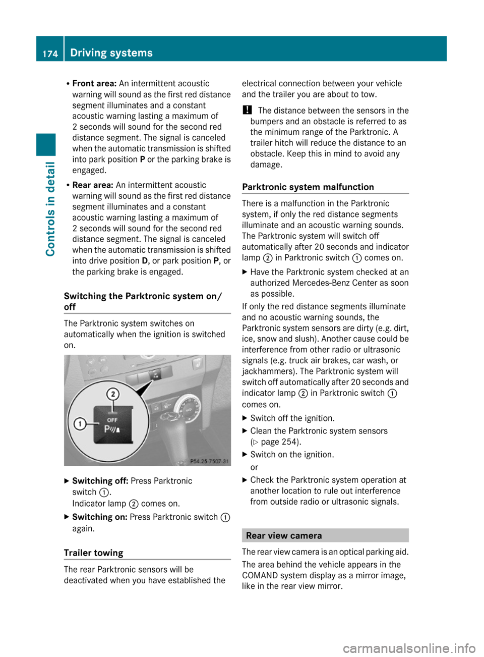
XSwitching off: Press Parktronic
switch :.
Indicator lamp ; comes on.
XSwitching on: Press Parktronic switch :
again.
Trailer towing
The rear Parktronic sensors will be
deactivated when you have established the
electrical connection between your vehicle
and the trailer you are about to tow.
! The distance between the sensors in the
bumpers and an obstacle is referred to as
the minimum range of the Parktronic. A
trailer hitch will reduce the distance to an
obstacle. Keep this in mind to avoid any
damage.
Parktronic system malfunction
There is a malfunction in the Parktronic
system, if only the red distance segments
illuminate and an acoustic warning sounds.
The Parktronic system will switch off
automatically after 20 seconds and indicator
lamp ; in Parktronic switch : comes on.
XHave the Parktronic system checked at an
authorized Mercedes-Benz Center as soon
as possible.
If only the red distance segments illuminate
and no acoustic warning sounds, the
Parktronic system sensors are dirty (e.g. dirt,
ice, snow and slush). Another cause could be
interference from other radio or ultrasonic
signals (e.g. truck air brakes, car wash, or
jackhammers). The Parktronic system will
switch off automatically after 20 seconds and
indicator lamp ; in Parktronic switch :
comes on.
XSwitch off the ignition.XClean the Parktronic system sensors
(Y page 254).
XSwitch on the ignition.
or
XCheck the Parktronic system operation at
another location to rule out interference
from outside radio or ultrasonic signals.
Rear view camera
The rear view camera is an optical parking aid.
The area behind the vehicle appears in the
COMAND system display as a mirror image,
like in the rear view mirror.
174Driving systemsControls in detail
X204_AKB; 3; 23, en-USd2ureepe,Version: 2.11.8.12009-07-16T19:16:58+02:00 - Seite 174
Page 178 of 344
Switching on or offXSwitching on: Switch on the ignition.XMake sure the rear view camera is switched
on in the COMAND system. For more
information refer to separate COMAND
operating instructions.
XSwitch on the COMAND system.XShift the automatic transmission to reverse
gear R.
The COMAND system display will show the
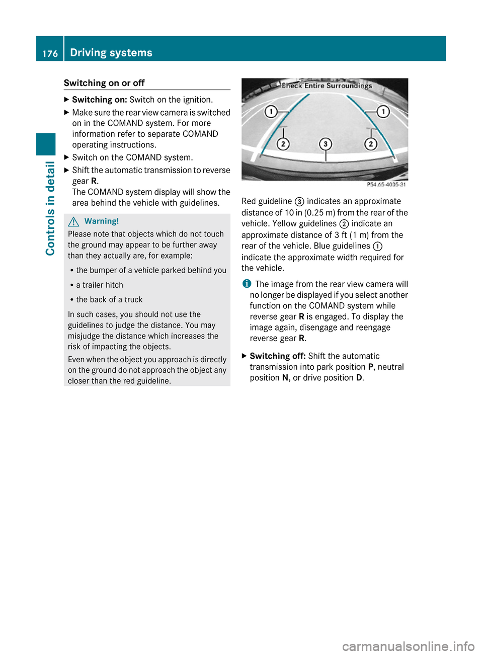
area behind the vehicle with guidelines.
GWarning!
Please note that objects which do not touch
the ground may appear to be further away
than they actually are, for example:
Rthe bumper of a vehicle parked behind you
Ra trailer hitch
Rthe back of a truck
In such cases, you should not use the
guidelines to judge the distance. You may
misjudge the distance which increases the
risk of impacting the objects.
Even when the object you approach is directly
on the ground do not approach the object any
closer than the red guideline.
Red guideline = indicates an approximate
distance of 10 in (0.25 m) from the rear of the
vehicle. Yellow guidelines ; indicate an
approximate distance of 3 ft (1 m) from the
rear of the vehicle. Blue guidelines :
indicate the approximate width required for
the vehicle.
iThe image from the rear view camera will
no longer be displayed if you select another
function on the COMAND system while
reverse gear R is engaged. To display the
image again, disengage and reengage
reverse gear R.
XSwitching off: Shift the automatic
transmission into park position P, neutral
position N, or drive position D.
176Driving systemsControls in detail
X204_AKB; 3; 23, en-USd2ureepe,Version: 2.11.8.12009-07-16T19:16:58+02:00 - Seite 176
Page 223 of 344
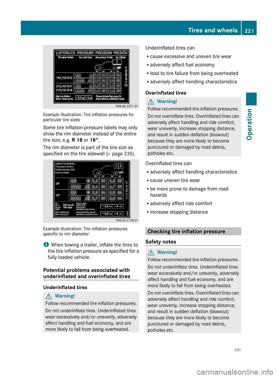
Example illustration: Tire inflation pressures forparticular tire sizes
Some tire inflation pressure labels may only
show the rim diameter instead of the entire
tire size, e.g. R 18 or 18".
The rim diameter is part of the tire size as
specified on the tire sidewall (Y page 235).
Example illustration: Tire inflation pressuresspecific to rim diameter
iWhen towing a trailer, inflate the tires to
the tire inflation pressure as specified for a
fully loaded vehicle.
Potential problems associated with
underinflated and overinflated tires
Underinflated tires
GWarning!
Follow recommended tire inflation pressures.
Do not underinflate tires. Underinflated tires
wear excessively and/or unevenly, adversely
affect handling and fuel economy, and are
more likely to fail from being overheated.
Underinflated tires can
Rcause excessive and uneven tire wear
Radversely affect fuel economy
Rlead to tire failure from being overheated
Radversely affect handling characteristics
Overinflated tires
GWarning!
Follow recommended tire inflation pressures.
Do not overinflate tires. Overinflated tires can
adversely affect handling and ride comfort,
wear unevenly, increase stopping distance,
and result in sudden deflation (blowout)
because they are more likely to become
punctured or damaged by road debris,
potholes etc.
Overinflated tires can
Radversely affect handling characteristics
Rcause uneven tire wear
Rbe more prone to damage from road
hazards
Radversely affect ride comfort
Rincrease stopping distance
Checking tire inflation pressure
Safety notes
GWarning!
Follow recommended tire inflation pressures.
Do not underinflate tires. Underinflated tires
wear excessively and/or unevenly, adversely
affect handling and fuel economy, and are
more likely to fail from being overheated.
Do not overinflate tires. Overinflated tires can
adversely affect handling and ride comfort,
wear unevenly, increase stopping distance,
and result in sudden deflation (blowout)
because they are more likely to become
punctured or damaged by road debris,
potholes etc.
Tires and wheels221OperationX204_AKB; 3; 23, en-USd2ureepe,Version: 2.11.8.12009-07-16T19:16:58+02:00 - Seite 221Z
Page 230 of 344
Loading Information placard with regards to
loading your vehicle.
Tire and Loading Information
GWarning!
Do not overload the tires by exceeding the
specified load limit as indicated on the Tire
and Loading Information placard on the
driver’s door B-pillar. Overloading the tires
can overheat them, possibly causing a
blowout. Overloading the tires can also result
in handling or steering problems, or brake
failure.
Tire and Loading Information placard
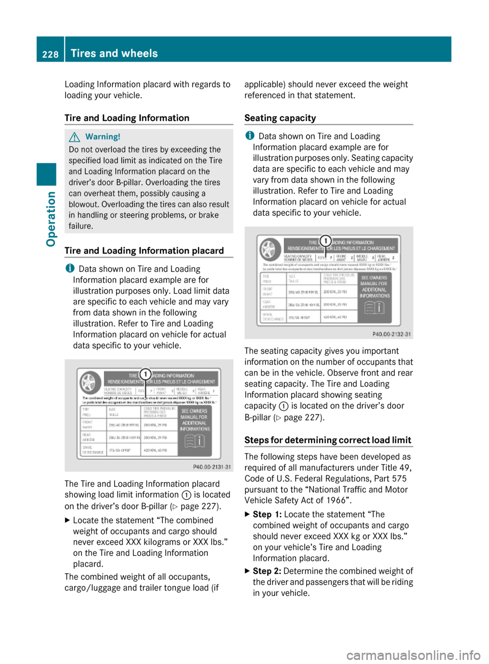
iData shown on Tire and Loading
Information placard example are for
illustration purposes only. Load limit data
are specific to each vehicle and may vary
from data shown in the following
illustration. Refer to Tire and Loading
Information placard on vehicle for actual
data specific to your vehicle.
The Tire and Loading Information placard
showing load limit information : is located
on the driver’s door B-pillar (Y page 227).
XLocate the statement “The combined
weight of occupants and cargo should
never exceed XXX kilograms or XXX lbs.”
on the Tire and Loading Information
placard.
The combined weight of all occupants,
cargo/luggage and trailer tongue load (if
applicable) should never exceed the weight
referenced in that statement.
Seating capacity
iData shown on Tire and Loading
Information placard example are for
illustration purposes only. Seating capacity
data are specific to each vehicle and may
vary from data shown in the following
illustration. Refer to Tire and Loading
Information placard on vehicle for actual
data specific to your vehicle.
The seating capacity gives you important
information on the number of occupants that
can be in the vehicle. Observe front and rear
seating capacity. The Tire and Loading
Information placard showing seating
capacity : is located on the driver’s door
B-pillar (Y page 227).
Steps for determining correct load limit
The following steps have been developed as
required of all manufacturers under Title 49,
Code of U.S. Federal Regulations, Part 575
pursuant to the “National Traffic and Motor
Vehicle Safety Act of 1966”.
XStep 1: Locate the statement “The
combined weight of occupants and cargo
should never exceed XXX kg or XXX lbs.”
on your vehicle’s Tire and Loading
Information placard.
XStep 2: Determine the combined weight of
the driver and passengers that will be riding
in your vehicle.
228Tires and wheelsOperation
X204_AKB; 3; 23, en-USd2ureepe,Version: 2.11.8.12009-07-16T19:16:58+02:00 - Seite 228
Page 231 of 344
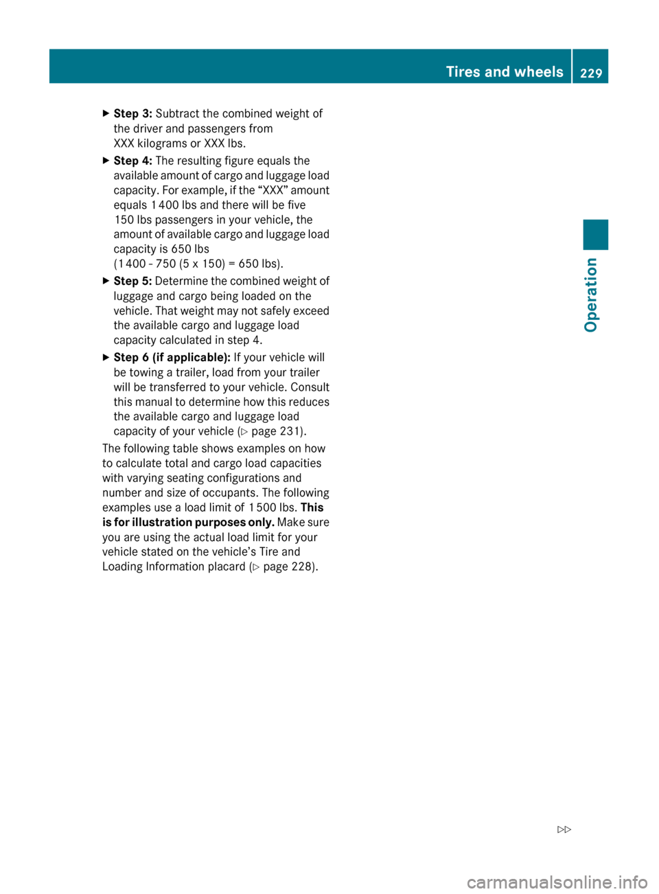
XStep 3: Subtract the combined weight of
the driver and passengers from
XXX kilograms or XXX lbs.XStep 4: The resulting figure equals the
available amount of cargo and luggage load
capacity. For example, if the “XXX” amount
equals 1 400 lbs and there will be five
150 lbs passengers in your vehicle, the
amount of available cargo and luggage load
capacity is 650 lbs
(1 400 - 750 (5 x 150) = 650 lbs).XStep 5: Determine the combined weight of
luggage and cargo being loaded on the
vehicle. That weight may not safely exceed
the available cargo and luggage load
capacity calculated in step 4.XStep 6 (if applicable): If your vehicle will
be towing a trailer, load from your trailer
will be transferred to your vehicle. Consult
this manual to determine how this reduces
the available cargo and luggage load
capacity of your vehicle ( Y page 231).
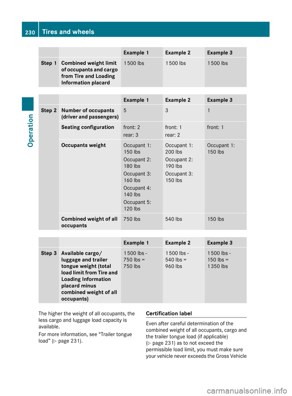
The following table shows examples on how
to calculate total and cargo load capacities
with varying seating configurations and
number and size of occupants. The following
examples use a load limit of 1 500 lbs. This
is for illustration purposes only. Make sure
you are using the actual load limit for your
vehicle stated on the vehicle’s Tire and
Loading Information placard ( Y page 228).
Tires and wheels229OperationX204_AKB; 3; 23, en-USd2ureepe,Version: 2.11.8.12009-07-16T19:16:58+02:00 - Seite 229Z
Page 232 of 344
Example 1Example 2Example 3Step 1Combined weight limit
of occupants and cargo
from Tire and Loading
Information placard1 500 lbs1 500 lbs1 500 lbsExample 1Example 2Example 3Step 2Number of occupants
(driver and passengers)531Seating configurationfront: 2
rear: 3front: 1
rear: 2front: 1Occupants weightOccupant 1:
150 lbs
Occupant 2:
180 lbs
Occupant 3:
160 lbs
Occupant 4:
140 lbs
Occupant 5:
120 lbsOccupant 1:
200 lbs
Occupant 2:
190 lbs
Occupant 3:
150 lbsOccupant 1:
150 lbsCombined weight of all
occupants750 lbs540 lbs150 lbsExample 1Example 2Example 3Step 3Available cargo/
luggage and trailer
tongue weight (total
load limit from Tire and
Loading Information
placard minus
combined weight of all
occupants)1 500 lbs -
750 lbs =
750 lbs1 500 lbs -
540 lbs =
960 lbs1 500 lbs -
150 lbs =
1 350 lbsThe higher the weight of all occupants, the
less cargo and luggage load capacity is
available.
For more information, see “Trailer tongue
load” ( Y page 231).Certification label
Even after careful determination of the
combined weight of all occupants, cargo and
the trailer tongue load (if applicable)
( Y page 231) as to not exceed the
permissible load limit, you must make sure
your vehicle never exceeds the Gross Vehicle
230Tires and wheelsOperation
X204_AKB; 3; 23, en-USd2ureepe,Version: 2.11.8.12009-07-16T19:16:58+02:00 - Seite 230
Page 233 of 344
Weight Rating (GVWR) and the Gross Axle
Weight Rating (GAWR) for either the front or
rear axle. You can obtain the GVWR and
GAWR from the certification label. The
certification label can be found on the driver’s
door B-pillar, see the “Technical data” section
(Y page 328).
Gross Vehicle Weight Rating (GVWR): The
total weight of the vehicle, all occupants, all
cargo, and the trailer tongue load (if
applicable) must never exceed the GVWR.
Gross Axle Weight Rating (GAWR): The total
allowable weight that can be carried by a
single axle (front or rear).
To assure that your vehicle does not exceed
the maximum permissible weight limits
(GVWR and GAWR for front and rear axle),
have the loaded vehicle (including driver,
passengers and all cargo and, if applicable,
trailer fully loaded) weighed on a suitable
commercial scale.
Trailer tongue load
The tongue load of any trailer is an important
weight to measure because it affects the load
you can carry in your vehicle. If a trailer is
towed, the tongue load must be added to the
weight of all occupants riding and any cargo
you are carrying in the vehicle. The tongue
load typically is 8% of the trailer weight and
everything loaded in it.
Maximum tire load
GWarning!
Do not overload the tires by exceeding the
specified load limit as indicated on the Tire
and Loading Information placard on the
driver’s door B-pillar. Overloading the tires
can overheat them, possibly causing a
blowout. Overloading the tires can also result
in handling or steering problems, or brake
failure.
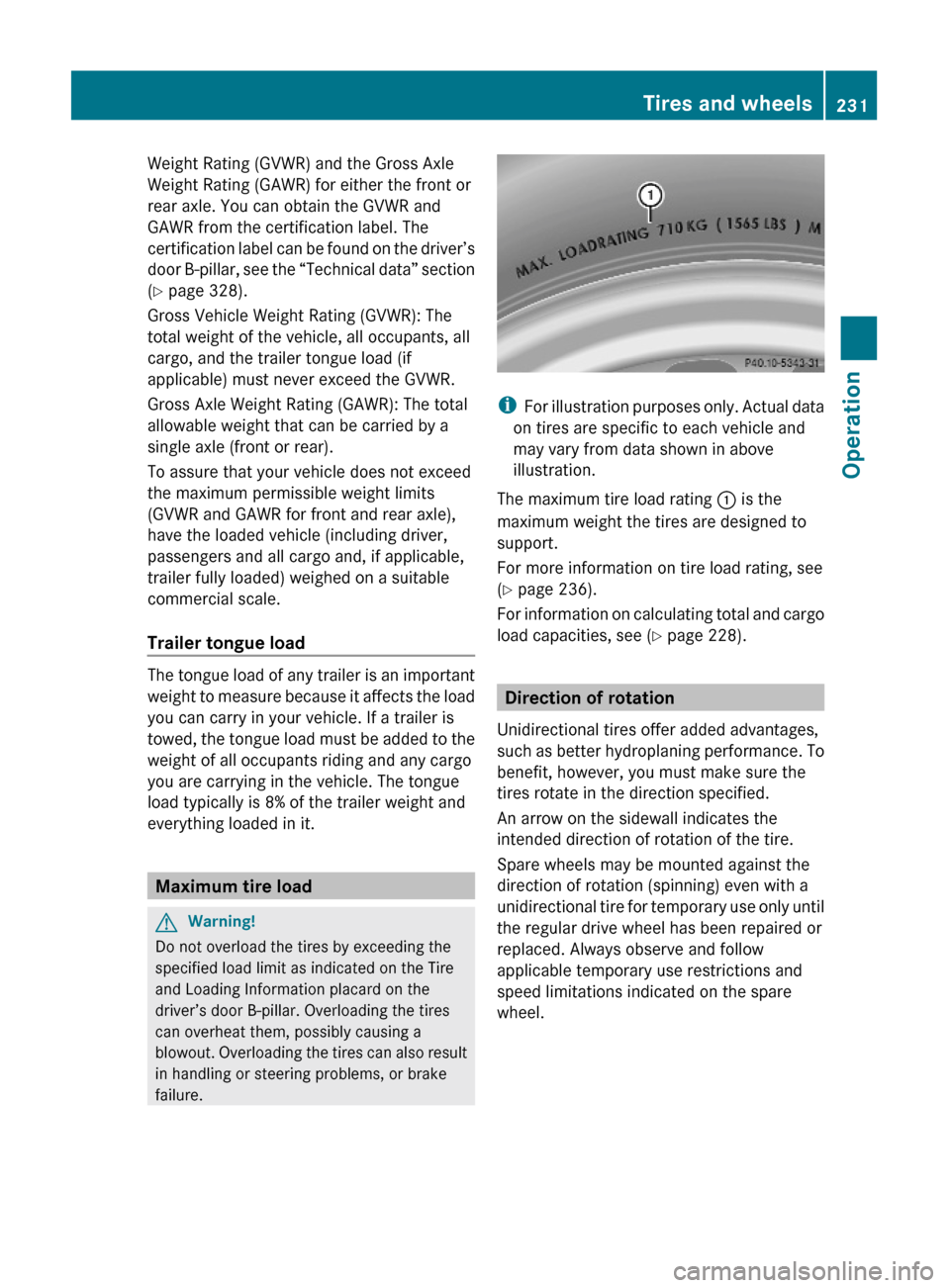
iFor illustration purposes only. Actual data
on tires are specific to each vehicle and
may vary from data shown in above
illustration.
The maximum tire load rating : is the
maximum weight the tires are designed to
support.
For more information on tire load rating, see
(Y page 236).
For information on calculating total and cargo
load capacities, see (Y page 228).
Direction of rotation
Unidirectional tires offer added advantages,
such as better hydroplaning performance. To
benefit, however, you must make sure the
tires rotate in the direction specified.
An arrow on the sidewall indicates the
intended direction of rotation of the tire.
Spare wheels may be mounted against the
direction of rotation (spinning) even with a
unidirectional tire for temporary use only until
the regular drive wheel has been repaired or
replaced. Always observe and follow
applicable temporary use restrictions and
speed limitations indicated on the spare
wheel.
Tires and wheels231OperationX204_AKB; 3; 23, en-USd2ureepe,Version: 2.11.8.12009-07-16T19:16:58+02:00 - Seite 231Z
Page 242 of 344
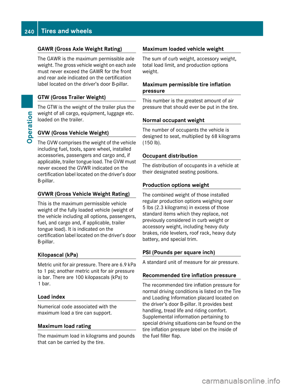
GAWR (Gross Axle Weight Rating)
The GAWR is the maximum permissible axle
weight. The gross vehicle weight on each axle
must never exceed the GAWR for the front
and rear axle indicated on the certification
label located on the driver’s door B-pillar.
GTW (Gross Trailer Weight)
The GTW is the weight of the trailer plus the
weight of all cargo, equipment, luggage etc.
loaded on the trailer.
GVW (Gross Vehicle Weight)
The GVW comprises the weight of the vehicle
including fuel, tools, spare wheel, installed
accessories, passengers and cargo and, if
applicable, trailer tongue load. The GVW must
never exceed the GVWR indicated on the
certification label located on the driver’s door
B-pillar.
GVWR (Gross Vehicle Weight Rating)
This is the maximum permissible vehicle
weight of the fully loaded vehicle (weight of
the vehicle including all options, passengers,
fuel, and cargo and, if applicable, trailer
tongue load). It is indicated on the
certification label located on the driver’s door
B-pillar.
Kilopascal (kPa)
Metric unit for air pressure. There are 6.9 kPa
to 1 psi; another metric unit for air pressure
is bar. There are 100 kilopascals (kPa) to
1 bar.
Load index
Numerical code associated with the
maximum load a tire can support.
Maximum load rating
The maximum load in kilograms and pounds
that can be carried by the tire.
Maximum loaded vehicle weight
The sum of curb weight, accessory weight,
total load limit, and production options
weight.
Maximum permissible tire inflation
pressure
This number is the greatest amount of air
pressure that should ever be put in the tire.
Normal occupant weight
The number of occupants the vehicle is
designed to seat, multiplied by 68 kilograms
(150 lb).
Occupant distribution
The distribution of occupants in a vehicle at
their designated seating positions.
Production options weight
The combined weight of those installed
regular production options weighing over
5 lbs (2.3 kilograms) in excess of those
standard items which they replace, not
previously considered in curb weight or
accessory weight, including heavy duty
brakes, ride levelers, roof rack, heavy duty
battery, and special trim.
PSI (Pounds per square inch)
A standard unit of measure for air pressure.
Recommended tire inflation pressure
The recommended tire inflation pressure for
normal driving conditions is listed on the Tire
and Loading Information placard located on
the driver’s door B-pillar. It provides best
handling, tread life and riding comfort.
Supplemental information pertaining to
special driving situations can be found on the
tire inflation pressure label on the inside of
the fuel filler flap.
240Tires and wheelsOperation
X204_AKB; 3; 23, en-USd2ureepe,Version: 2.11.8.12009-07-16T19:16:58+02:00 - Seite 240