2010 MERCEDES-BENZ CLS COUPE key
[x] Cancel search: keyPage 284 of 337
X
Screw the valve insert back into the valve.
X Screw the valve cap back on. Flat tyre
Preparing the vehicle
Your vehicle may be equipped with:
R a TIREFIT kit
R an emergency spare wheel
R MOExtended tyres (tyres with run-fla tchar-
acteristics) (Y page 289)
i Vehicle preparation is not necessary on
vehicles with MOExtended tyres.
i Vehicles with MOExtended tyres are not
equipped with a TIREFIT kit at the factory.
It is therefore recommended that you addi-
tionally equip your vehicle with a TIREFIT kit
if you fit tyres that do not feature run-flat
properties, e.g. winter tyres. You can obtain
aT IREFIT kit from aMercedes-Benz Service
Centre, for example.
X Vehicles with AIRMATIC: make sure that
"normal" level is selected (Y page 167).
X Stop the vehicle as far away as possible
from traffic on solid, non-slippery and level
ground.
X Switch on the hazard warning lamps.
X Bring the fron twheels into the straight-
ahead position.
X Move the DIRECT SELECT lever to P.
X Switch off the engine.
X Vehicles without KEYLESS-GO: remove
the key from the ignition lock.
X Vehicles with KEYLESS-GO: open the
driver's door.
The on-board electronics have status 0,
which is the same as the key having been
removed.
X Vehicles with KEYLESS-GO: remove the
Start/Stop button from the ignition lock
(Y page 129). X
All occupants must get out of the vehicle.
Make sure that they are not endangered as
they do so.
X Make sure that no one is near the danger
area whilst a wheel is being changed. Any-
one who is not directly assisting in the
wheel change should, for example, stand
behind the barrier.
X Get out of the vehicle. Pay attention to traf-
fic conditions when doing so.
X Close the driver's door.
X Place the warning triangle (Y page 278) a
suitable distance away.O bserve legal
requirements. TIREFIT kit
Using the TIREFIT kit You can use the TIREFIT kit to seal small
punctures, particularly those in the tyre tread.
You can use TIREFIT at outside temperatures
down to -20 †.
G
Risk of accident
In the following situations, your safety is at
particular risk as tyre sealant is unable to pro-
vide sufficient breakdown assistance:
R there are cuts or punctures in the tyre
greater than 4 mm.
R the wheel rim is damaged.
R you have driven at very low tyre pressures
or on a flat tyre.
Do not drive any further. Consult a qualified
specialist workshop which has the necessary
specialist knowledge and tools to carry out
the work required.
Mercedes-Benz recommends that you use a
Mercedes-Benz Service Centre for this pur-
pose. In particular, work relevant to safety or
on safety-related system smust be carried out
at a qualified specialist workshop. Flat tyre
281Breakdown assistance Z
Page 285 of 337
X
Do not remove any foreign objects which
have penetrated the tyre, e.g .screws or
nails.
X Remove the tyre sealant bottle, the accom-
panying "max. 80 km/h" sticker and the
tyre inflation compressor from the stowage
well underneath the boo tfloor
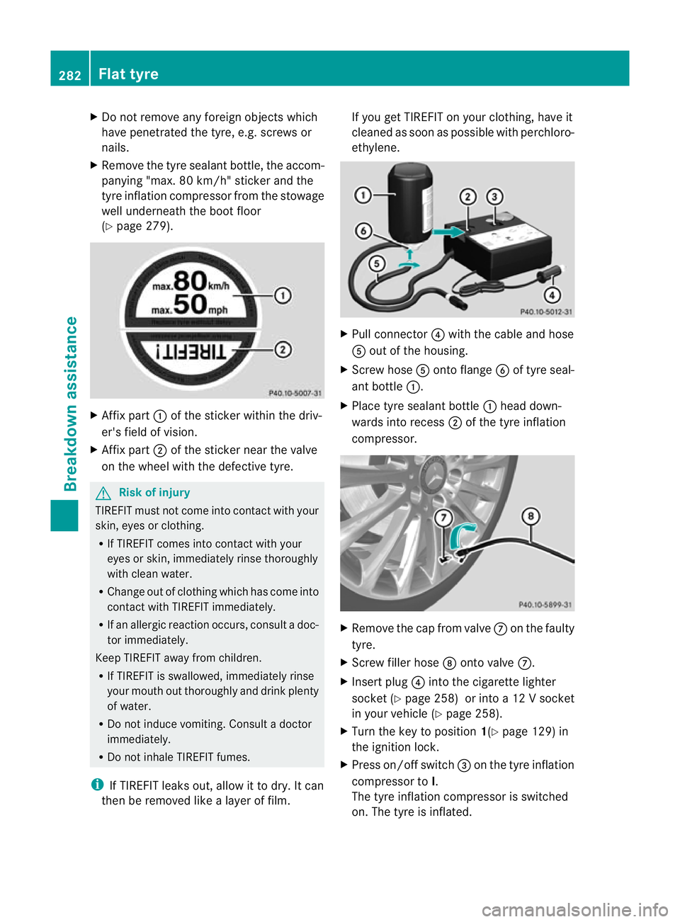
(Y page 279). X
Affix part :of the sticker within the driv-
er's field of vision.
X Affix part ;of the sticker near the valve
on the wheel with the defective tyre. G
Risk of injury
TIREFIT must not com einto contact with your
skin, eyes or clothing.
R If TIREFIT comes into contact with your
eyes or skin, immediately rinse thoroughly
with clean water.
R Change ou tofclothing which has come into
contact with TIREFIT immediately.
R If an allergic reaction occurs, consult a doc-
tor immediately.
Keep TIREFIT away fro mchildren.
R If TIREFIT is swallowed, immediately rinse
your mouth out thoroughly and drink plenty
of water.
R Do not induce vomiting. Consult a doctor
immediately.
R Do not inhale TIREFIT fumes.
i If TIREFIT leaks out, allow it to dry. It can
then be removed like a layer of film. If you get TIREFIT on your clothing, have it
cleaned as soon as possible with perchloro-
ethylene.
X
Pull connector ?with the cable and hose
A out of the housing.
X Screw hose Aonto flange Bof tyre seal-
ant bottle :.
X Place tyre sealant bottle :head down-
wards into recess ;of the tyre inflation
compressor. X
Remove the cap from valve Con the faulty
tyre.
X Screw filler hose Donto valve C.
X Insert plug ?into the cigarette lighter
socket (Y page 258) or into a12 V socket
in you rvehicle (Y page 258).
X Turn the key to position 1(Ypage 129) in
the ignition lock.
X Press on/off switch =on the tyre inflation
compressor to I.
The tyre inflation compressor is switched
on. The tyre is inflated. 282
Flat tyreBreakdown assistance
Page 291 of 337

gency spare wheel (Y
page 288) and then
lower the vehicle ( Ypage 288).
or
X Vehicles with a "Minispare" emer-
gency spare wheel: lower the vehicle
(Y page 288)
Inflating the collapsible emergency
spare wheel G
Risk of accident
Inflate the collapsible emergency spare wheel
before lowering the vehicle. You could other-
wise damage the wheel rim. X
Pull plug ?and the air hose out of the
housing.
X Remove the cap from the valve on the col-
lapsible emergency spare wheel.
X Screw union nut :on the air hose onto the
valve.
X Make sure on/offs witchAof the tyre
inflatio ncompressor is set to 0.
X Insert plug ?into the socket of the ciga-
rette lighter (Y page 258) or into a 12 V
power socket (Y page 258) in your vehicle.
X Make sure that the key is in position
1(Y page 129) in the ignition lock.
X Press on/offs witchAon the tyre inflation
compressor to I.
The tyre inflatio ncompressor is switched
on. The tyre is inflated. The tyre pressure is
read at pressure gauge =.!
Do not operate the tyre inflation com-
pressor for longer than eight minutes at a
time without a break. It may otherwise
overheat.
The tyre inflation compressor can be oper-
ated again once it has cooled down.
X Pump the tyre to the specified tyre pres-
sure.
The specified tyre pressure is printed on
the yellow label of the emergency spare
wheel.
X When the specified tyre pressure has been
reached, press on/offs witchAon the
electric air pump to 0.
The tyre inflatio ncompressor is switched
off.
X Turn the key to position 0in the ignition
lock.
X If the tyre pressure is higher than the speci-
fied pressure, press pressure release but-
ton ;until the correct tyre pressure has
been reached.
X Unscrew union nut :on the air hose from
the valve.
X Screw the valve cap ontot he collapsible
emergency spare wheel valve again.
X Stow plug ?and the air hose in the lower
section of the pump housing.
X Stow the tyre inflation compressor in the
designated place in the vehicle.
Lowering the vehicle G
Risk of accident
Inflate the collapsible emergency spare wheel
before lowering the vehicle. You could other-
wise damage the wheel rim.
X Turn the crank of the jack anti-clockwise
until the vehicle is once again standing
firmly on the ground.
X Place the jack to one side. 288
Flat tyreBreakdown assistance
Page 294 of 337
recycled in an environmen-
tally responsible manner.
Dispose of batteries in an
environmentally responsible
manner. Take discharged
batteries to a qualified spe-
cialist workshop, e.g. a
Mercedes-Benz Service
Centre, or to a special col-
lection point for old batter-
ies.
G
Risk of injury
For safety reasons, Mercedes-Benz recom-
mends that you only use batteries which have
been tested and approved for yourv ehicle by
Mercedes-Benz .These batteries provide
increased impact protection to prevent vehi-
cle occupants from suffering acid burns
should the battery be damaged in the event
of an accident.
To prevent acid burns, observe the following
safety notes when handling batteries:
R do not lean over the battery.
R do not place any metal objects on a battery.
Otherwise, you could cause a short circuit
and the battery's gas mixture could ignite.
R make sure that you do not create an elec-
trostatic charge, e.g. by wearing synthetic
clothing or as a result of friction on fabrics.
Therefore, you should not pull or slide the
battery over carpets or other synthetic
materials.
R never touch the battery first. To discharge
a possible electrostatic charge, step out of
the vehicle first and touch the bodywork.
R do not wipe the battery using a cloth. The
battery may explode as a result of electro-
static charge or due to flying sparks.
! Switch off the engine and remove the key
before disconnecting the terminal clamps
from the battery. On vehicles with KEY-
LESS-GO, make sure that the ignition is
switched off. Check that all the indicator
lamps in the instrumentc luster are off.You may otherwise destroy electronic compo-
nents, such as the alternator.
i Remove the key if you park the vehicle
and do not require any electrical consum-
ers. The vehicle will then use very little
energy, thus conserving battery power.
Mercedes-Benz recommends that you do not
carry out work on batteries yourself, e.g.
removing, charging or replacing. Always have
this work performed at aqualified specialist
workshop, e.g. a Mercedes-Ben zService
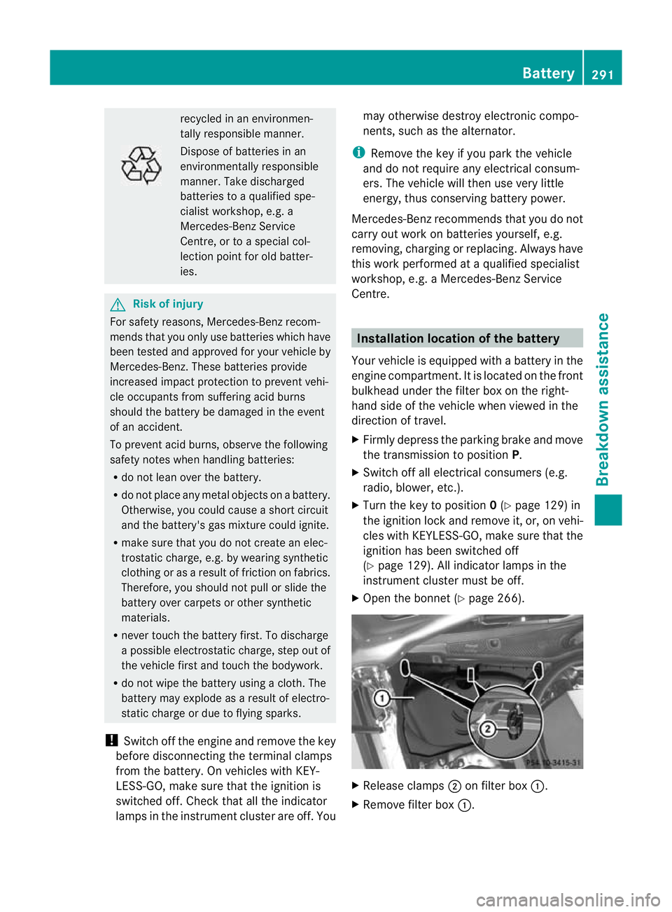
Centre. Installation location of the battery
Your vehicle is equipped with a battery in the
engine compartment .Itis located on the front
bulkhead under the filter box on the right-
hand side of the vehicle when viewed in the
direction of travel.
X Firmly depress the parking brake and move
the transmission to position P.
X Switch off all electrical consumers (e.g.
radio, blower, etc.).
X Turn the key to position 0(Y page 129) in
the ignition lock and remove it, or, on vehi-
cles with KEYLESS-GO, make sure that the
ignition has been switched off
(Y page 129). All indicator lamps in the
instrument cluster must be off.
X Open the bonnet (Y page 266). X
Release clamps ;on filter box :.
X Remove filter box :. Battery
291Breakdown assistance Z
Page 299 of 337
G
Risk of accident
The vehicle is braked whe nthe HOLD function
or DISTRONIC PLUS is activated. Therefore,
deactivate HOLD and DISTRONIC PLUS if the
vehicle is to be towed.
It is better to have the vehicle transported
than to have it towed.
! You may tow the vehicle for a maximum
of 50 km. A towing speed of 50 km/h must
not be exceeded.
For towing distances over 50 km, the entire
vehicle must be lifted up and transported.
! Only secure the tow rope or towing bar to
the towing eyes. The vehicle may otherwise
be damaged.
! Do not use the towing eye for recovery,
as this could damage the vehicle. If in
doubt, recover the vehicle with a crane.
! Pull away smoothly when towing away or
tow-starting a vehicle. If the tractive power
is too high, the vehicles could be damaged.
! To tow vehicles with KEYLESS-GO, use
the key instead of the Start/Stop button.
The automatic transmission may otherwise
switch to position Pwhen you open the
driver's or front-passenger door which
could damage the transmission.
! Vehicles with automatic transmission
must not be tow-started. The transmission
may otherwise be damaged.
The automatic transmission must be in posi-
tion Nwhen the vehicle is being towed.
The battery must be connected and charged.
Otherwise, you:
R cannot turn the key in the ignition lock to
position 2
R cannot shift the automatic transmission to
position N
i Switch off the automatic locking feature
(Y page 74) before the vehicle is towed. You
could otherwise be locked out when push-
ing or towing the vehicle. Deactivate tow-away protection
(Y
page 64) before the vehicle is towed. Fitting/removing the towing eye
Fitting the towing eye X
Remove the towing eye from the vehicle
tool kit (Y page 279). G
Risk of injury
The exhaust tail pipe may be hot. You could
burn yourself if you touch the tail pipe. Be
particularly careful when removing the rear
cover.
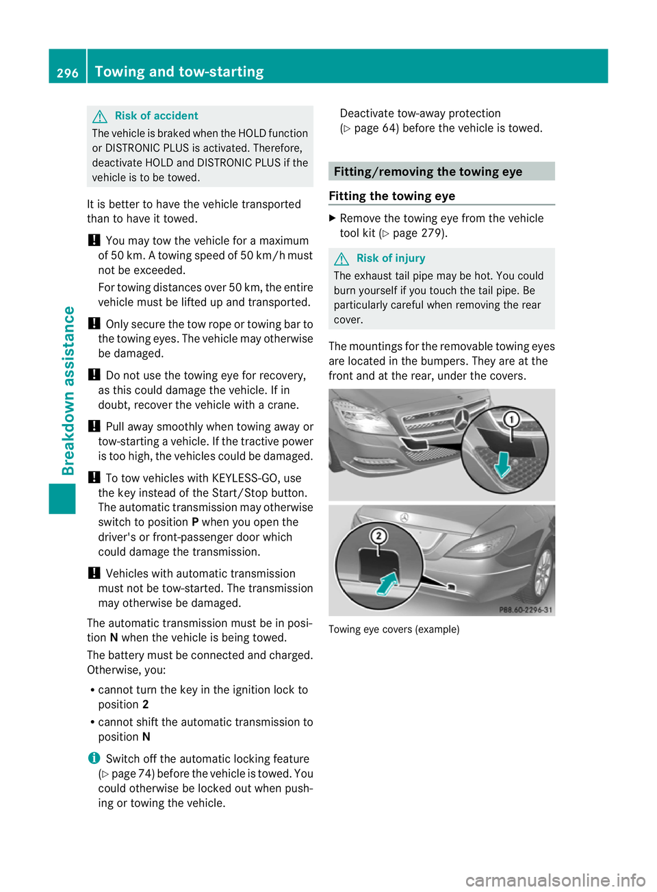
The mountings for the removable towing eyes
are located in the bumpers. They are at the
front and at the rear, under the covers. Towing eye covers (example)296
Towing and tow-startingBreakdown assistance
Page 300 of 337
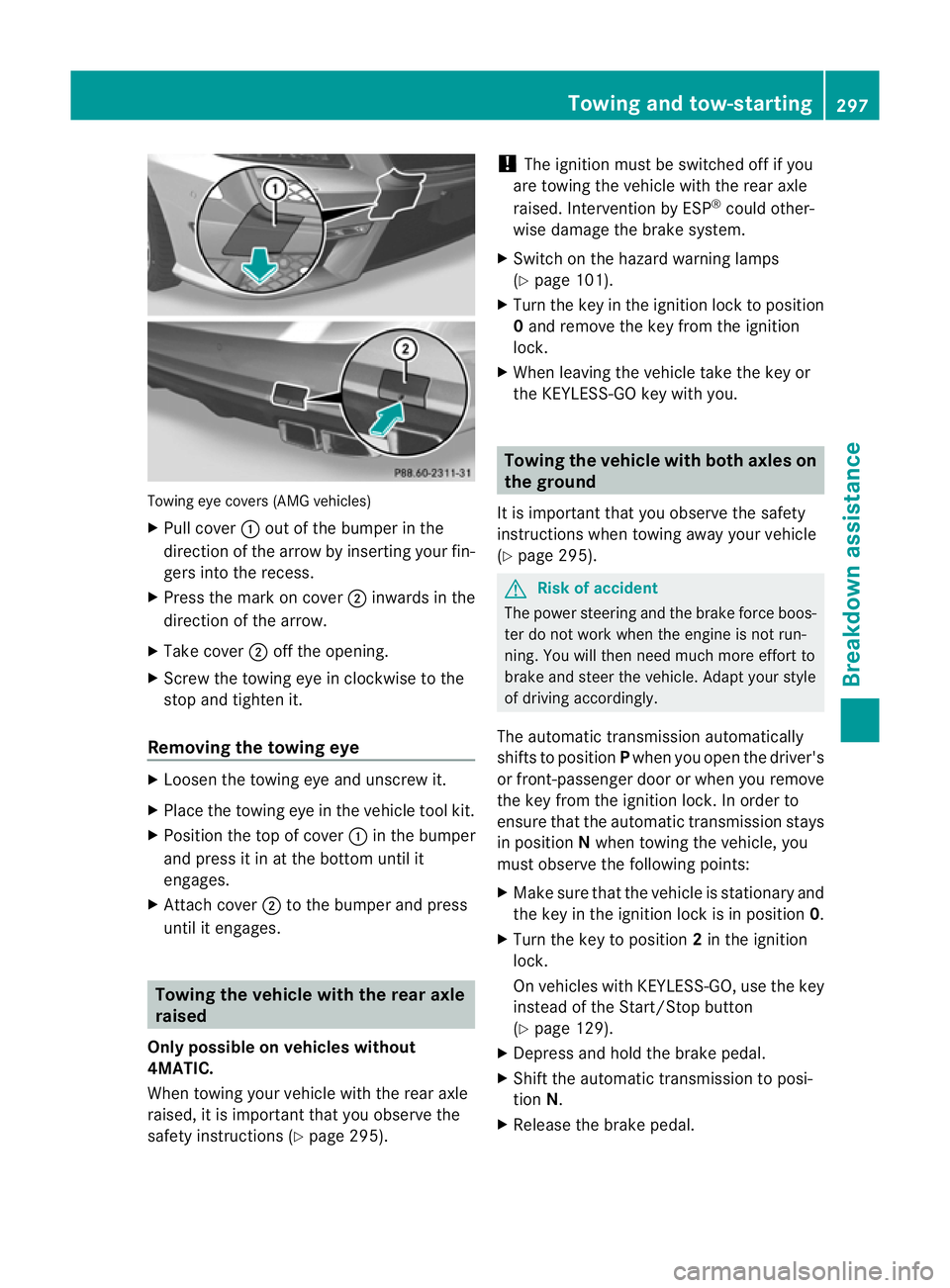
Towing eye covers (AMG vehicles)
X
Pull cover :out of the bumper in the
direction of the arrow by inserting your fin-
gers into the recess.
X Press the mark on cover ;inwards in the
direction of the arrow.
X Take cover ;off the opening.
X Screw the towing eye in clockwise to the
stop and tighten it.
Removing the towing eye X
Loosen the towing eye and unscrew it.
X Place the towing eye in the vehicle tool kit.
X Position the top of cover :in the bumper
and press it in at the bottom until it
engages.
X Attach cover ;to the bumper and press
until it engages. Towing the vehicle with the rear axle
raised
Only possible on vehicles without
4MATIC.
When towing your vehicle with the rear axle
raised, it is important that you observe the
safety instructions (Y page 295). !
The ignition must be switched off if you
are towing the vehicle with the rear axle
raised. Intervention by ESP ®
could other-
wise damage the brake system.
X Switch on the hazard warning lamps
(Y page 101).
X Turn the key in the ignition lock to position
0and remove the key from the ignition
lock.
X When leaving the vehicle take the key or
the KEYLESS-GO key with you. Towing the vehicle with both axles on
the ground
It is important that you observe the safety
instructions when towing away your vehicle
(Y page 295). G
Risk of accident
The power steering and the brake force boos-
ter do not work when the engine is not run-
ning. You will then need much more effort to
brake and steer the vehicle. Adapt your style
of driving accordingly.
The automatic transmission automatically
shifts to position Pwhen you open the driver's
or front-passenger door or when you remove
the key from the ignition lock. In order to
ensure that the automatic transmission stays
in position Nwhen towing the vehicle, you
must observe the following points:
X Make sure that the vehicle is stationary and
the key in the ignition lock is in position 0.
X Turn the key to position 2in the ignition
lock.
On vehicles with KEYLESS-GO, use the key
instead of the Start/Stop button
(Y page 129).
X Depress and hold the brake pedal.
X Shift the automatic transmission to posi-
tion N.
X Release the brake pedal. Towing and tow-starting
297Breakdown assistance Z
Page 301 of 337
X
Switch on the hazard warning lamps
(Y page 101).
X Leave the key in position 2in the ignition
lock.
i Whe ntowing with the hazard warning
lamps switched on, use the combination
switch as usual to signal achange of direc-
tion. In this case, only the turn signals for
the desired direction flash. When the com-
bination switch is reset, the hazard warning
lamps start flashing again. Transporting the vehicle
The towing eye can be used to pull the vehicle
onto a trailer or transporter for transporting
purposes.
X Vehicles with automatic transmission:
turn the key to position 2in the ignition
lock.
X Shift the automatic transmission to posi-
tion N.
As soon as the vehicle is loaded:
X Prevent the vehicle from rolling away by
applying the parking brake.
X Turn the key in the ignition lock to position
0and remove the key from the ignition
lock.
X Secure the vehicle.
! Only lash the vehicle down by the wheels
or wheel rims, not by parts of the vehicle
such as axle or steering components. Oth-
erwise, the vehicle could be damaged. Electrical fuses
Important safety notes
The fuses in your vehicle serve to close down
faulty circuits. If afuse blows, all the compo-
nents on the circuit and their functions will
fail. G
Risk of fire
Only use fuses that have been approved for
Mercedes-Ben zvehicles and which have the
correct fuse rating for the systems con-
cerned. Do not attempt to repair or bridge
faulty fuses. Otherwise, a circuit overload
could cause a fire. Have the cause traced and
rectified at a qualified specialist workshop,
e.g. a Mercedes-Benz Service Centre.
Blown fuses must be replaced with fuses of
the same rating, which you can recognise by
the colour and value. The fuse ratings are lis-
ted in the fuse allocation chart .AMercedes-
BenzS ervice Centre will be happy to advise
you.
If the newly inserted fuse also blows, have the
cause traced and rectified at a qualified spe-
cialist workshop, e.g. a Mercedes-Benz
Service Centre.
! Only use fuses that have been approved
for Mercedes-Benzv ehicles and which
have the correct fuse rating for the system
concerned. Otherwise, components or sys-
tems could be damaged. Before changing a fuse
X Park the vehicle and apply the parking
brake.
X Switch off all electrical consumers.
X Remove the key from the ignition lock.
The fuses are located in various fuse boxes:
R fuse box in the engine compartment on the
left-hand side of the vehicle, when viewed
in the direction of travel
R fuse box in the boot on the right when
viewed in the direction of travel
The fuse allocation chart is located in the
vehicle tool kit (Y page 279) in the stowage
compartment under the boot floor. 298
Electrical fusesBreakdown assistance
Page 302 of 337
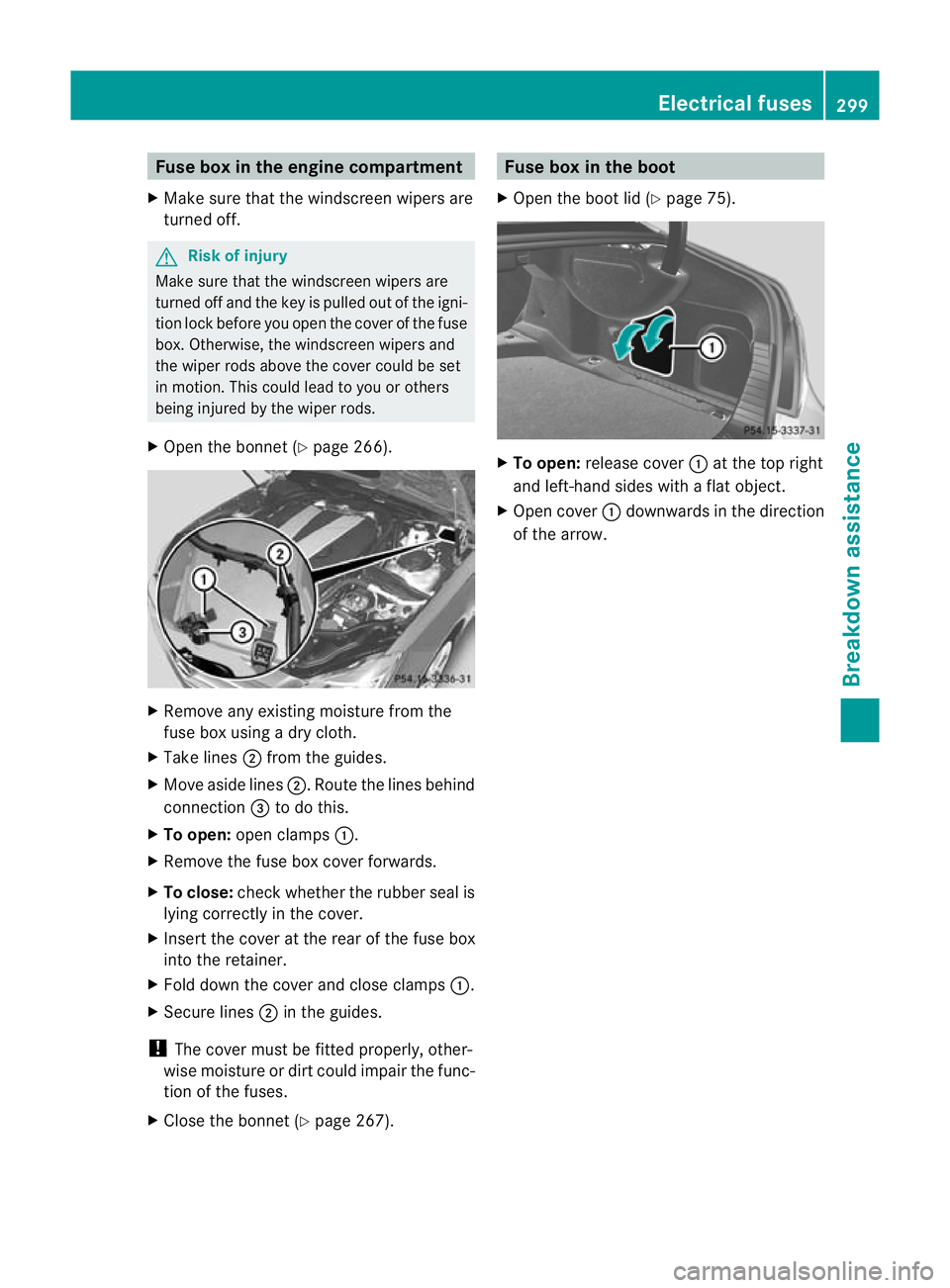
Fuse box in the engine compartment
X Make sure that the windscree nwipers are
turned off. G
Risk of injury
Make sure that the windscreen wipers are
turned off and the key is pulled out of the igni-
tion lock before you open the cover of the fuse
box. Otherwise, the windscreen wipers and
the wiper rods above the cover could be set
in motion. This could lead to you or others
being injured by the wiper rods.
X Open the bonnet (Y page 266).X
Remove any existing moisture fro mthe
fuse box using a dry cloth.
X Take lines ;from the guides.
X Move aside lines ;.Route the lines behind
connection =to do this.
X To open: open clamps :.
X Remove the fuse box cover forwards.
X To close: check whether the rubber seal is
lying correctly in the cover.
X Insert the cover at the rear of the fuse box
into the retainer.
X Fold down the cover and close clamps :.
X Secure lines ;in the guides.
! The cover must be fitted properly, other-
wise moisture or dirt could impair the func-
tion of the fuses.
X Close the bonnet (Y page 267). Fuse box in the boot
X Open the boot lid (Y page 75). X
To open: release cover :at the top right
and left-hand sides with a flat object.
X Open cover :downwards in the direction
of the arrow. Electrical fuses
299Breakdown assistance Z