2010 JAGUAR XFR display
[x] Cancel search: displayPage 1530 of 3039

6 Clockspring 7 Steering wheel audio switches 8 Upshift paddle switch 9 Downshift paddle switch 10 Instrument cluster 11 JaguarDrive selector
JAGUARDRIVE SELECTOR System Operation
Rotation of the JaguarDrive selector to any of the five positions is sensed by the TCM (transmission control module) via the
high speed CAN bus. A LIN bus connection is also provided, but is only used in the event of a CAN bus failure as a back-up. The TCM then reacts according to the selected position. The JaguarDrive selector is a magnetic system using Hall effect sensors to determine the position of the selector.
The S (sport) position selection allows the TCM to operate the transmission using the semi-automatic Jaguar sequential shift. Gear selections are sensed by the TCM when the driver operates the steering wheel paddle switches. Once the JaguarDrive selector position is confirmed, the TCM outputs appropriate information on the high speed CAN bus which is received by the instrument cluster to display the gear selection information in the message center.
Refer to: Information and Message Center (413-08 Information and Message Center, Description and Operation).
The paddles can also be used on a temporary basis when the JaguarDrive selector is in the D (drive) position to override the
automatic gear selection if required.
PARK INTERLOCK AND NEUTRAL LOCK
Neutral lock is a requirement for the JaguarDrive selector. The selector is always locked at ignition on when the engine is not
running, except after an engine stall when the selector is not in P (park) or N (neutral).
If, when driving with the JaguarDrive selector in S, D or R (reverse) at a speed of more than 5 km/h (3 mph), the driver selects
P or N:
Without the brake pedal pressed, the JaguarDrive selector will be immediately locked once the vehicle speed falls to
below 5 km/h (3 mph).
With the brake pedal pressed, the JaguarDrive selector will remain locked for as long as the brake pedal remains
pressed, regardless of vehicle speed.
The transmission will only engage park once the vehicle speed is less than 2 km/h (1 mph).
If the driver selects N and releases the brake pedal with a vehicle speed of less than 5 km/h (3 mph), the JaguarDrive selector
will be locked 2 seconds after N is selected. The selector will remain locked until the driver presses the brake pedal again.
To ensure that a driver request to change from a non-driving range (N for example) to a driving range (D for example), the park
interlock and neutral lock features are used in conjunction with the intermediate position.
If the transmission receives a range change request without the brake pedal pressed, the TCM initiates a soft lock function. The transmission will remain in park or neutral, depending on the starting position.
If a transmission position letter is flashing in the message center and the vehicle has no drive, the driver must:
Press the brake pedal.
Reselect N or P on the JaguarDrive selector.
Select the required driving range, ensuring that the brake pedal is pressed.
Rocking Function
The rocking function compliments the neutral lock function. For all changes from a non-driving range to a driving range, it is
necessary to press the brake pedal (to release either the park interlock or neutral lock).
In situations where the driver will require to change the gear selection from R to D, or from D to R, without brake pedal input
(car park maneuvering, 3 point turns or 'rocking' the vehicle from a slippery surface for example), the rocking function gives a 2
second lock delay when N is selected on the JaguarDrive selector and the brake pedal is not pressed.
Intermediate Position
If the JaguarDrive selector is rotated slowly from P to S and back to position P with the brake pedal pressed, the R or D
position display letter in the message center will flash and the transmission will remain in park or neutral depending on the
previous starting position of the selector.
If the brake pedal is released when R or D is flashing in the message center and the JaguarDrive selector is rotated to the R or
D position, the required range will not be selected and the transmission will remain in park or neutral, depending on the
previous starting position. This feature is known as soft lock.
If the driving range letter in the message center is flashing and the vehicle has no drive, the driver should depress the brake
pedal to reselect N or P, and then select the required driving range while the brake pedal remains pressed.
Page 1595 of 3039
Published: 28-Jul-2014
Fuel Tank and Lines - V8 5.0L Petrol/V8 S/C 5.0L Petrol - Fuel Tank and
Lines
Diagnosis and Testing
Principle of Operation
For a detailed description of the fuel tank and lines system and operation, refer to the relevant Description and Operation
section of the workshop manual. REFER to: (310-01C Fuel Tank and Lines - V8 5.0L Petrol/V8 S/C 5.0L Petrol)
Fuel Tank and Lines (Description and Operation), Fuel Tank and Lines (Description and Operation), Fuel Tank and Lines (Description and Operation).
Inspection and Verification
WARNINGS:
Eye protection must be worn at all times when working on or near any fuel related components. Failure to follow this
instruction may result in personal injury.
This procedure involves fuel handling. Be prepared for fuel spillage at all times and always observe fuel handling
precautions. Failure to follow this instruction may result in personal injury.
After carrying out repairs, the fuel system must be checked visually for leaks. This should be done after the engine has
been run, but with the engine switched OFF. Failure to follow this instruction may result in personal injury.
If taken internally, DO NOT induce vomiting. Seek immediate medical attention. Failure to follow this instruction may
result in personal injury.
If fuel contacts the eyes, flush the eyes with cold water or eyewash solution and seek medical attention. Failure to follow
this instruction may result in personal injury.
Wash hands thoroughly after handling, as prolonged contact may cause irritation. Should irritation develop, seek medical
attention. Failure to follow this instruction may result in personal injury.
CAUTIONS:
Before disconnecting any part of the system, it is imperative that all dust, dirt and debris is removed from around
components to prevent ingress of foreign matter into the fuel system. Failure to follow this instruction may result in damage to
the vehicle.
It is essential that absolute cleanliness is observed when working with these components. Always install blanking plugs
to any open orifices or lines. Failure to follow this instruction may result in damage to the vehicle.
Diagnosis by substitution from a donor vehicle is NOT acceptable. Substitution of control modules does not guarantee
confirmation of a fault, and may also cause additional faults in the vehicle being tested and/or the donor vehicle.
NOTES:
Check and rectify basic faults before beginning diagnostic routines involving pinpoint tests.
When measuring fuel sender resistance values with a multimeter, it is critical to use the correct multimeter setting. The
multimeter should not be on the 'Auto' setting and must be set to 'Manual'. This will help prevent incorrect diagnosis and
unnecessary replacement of fuel senders. If the multimeter range is set at 'Auto' then, during a sweep of the sender from 50
Ohms to 998 Ohms, the multimeter has to change its measurement range. For approximately 1 second, during the range switch
over point, the multimeter display indicates an open circuit. This can lead to a mis-diagnosis of a fuel sender fault.
1. Verify the customer concern
2. Visually inspect for obvious signs of damage and system integrity
Page 1642 of 3039
longitudinal axis of the vehicle. The radar operates at millimetric wavelengths (76 - 77 GHz) and transmits a frequency
modulated continuous wave signal at a relatively low power level (no high power pulses).
With the ignition ON, the adaptive speed control module is powered up but no radar transmissions are emitted until the
vehicle is in motion.
In follow mode a set speed is selected in the normal speed control manner and this speed is maintained until a slower vehicle
is encountered in the lane ahead. When the vehicle ahead comes within the effective range of the radar sensor, the system
identifies it as a target vehicle and an icon is illuminated on the instrument cluster to indicate that the system is in "follow
mode". When the distance between the two vehicles closes to a set time gap, the adaptive speed control system closes the
throttle and if necessary applies the brakes to maintain the set time gap. Follow mode is effectively a closed loop system. If
several vehicles are ahead, the closest vehicle is chosen as the target to follow. If the target vehicle moves out of radar range,
or if either vehicle changes lane or drops below the minimum operating speed, the system exits follow mode and the follow
mode icon is extinguished. The adaptive speed control system will only raise its speed to the originally set speed, it will not
accelerate past this speed to maintain a time gap.
Driver operation of the foot brake or control switches will immediately cancel adaptive speed control.
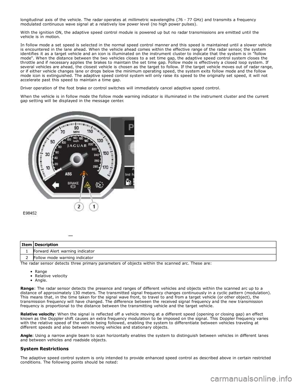
When the vehicle is in follow mode the follow mode warning indicator is illuminated in the instrument cluster and the current
gap setting will be displayed in the message center.
The radar sensor detects three primary parameters of objects within the scanned arc. These are:
Range
Relative velocity
Angle.
Range: The radar sensor detects the presence and ranges of different vehicles and objects within the scanned arc up to a
distance of approximately 130 meters. The transmitted signal frequency changes continuously in a cyclic pattern (modulation).
This means that, in the time taken for the signal wave front, to travel to and from a target vehicle (or other object), the
transmission frequency will have changed. The difference between the received signal frequency and the new transmission
frequency is proportional to the distance between the transmitting vehicle and the target vehicle.
Relative velocity: When the signal is reflected off a vehicle moving at a different speed (opening or closing gap) an effect
known as the Doppler shift causes an extra frequency modulation to be imposed on the signal. This Doppler frequency varies
with the relative speed of the vehicle being followed, enabling the system to differentiate between vehicles traveling at
different speeds and also between moving vehicles and stationary objects.
Angle: Using a narrow angle beam to scan horizontally enables the system to distinguish between vehicles in different lanes
and between vehicles and roadside objects.
System Restrictions
The adaptive speed control system is only intended to provide enhanced speed control as described above in certain restricted
conditions. The following points should be noted: Item Description 1 Forward Alert warning indicator 2 Follow mode warning indicator
Page 1686 of 3039
Published: 11-May-2011
Climate Control - Air Distribution and Filtering - System Operation and
Component Description
Description and Operation
Control Diagram
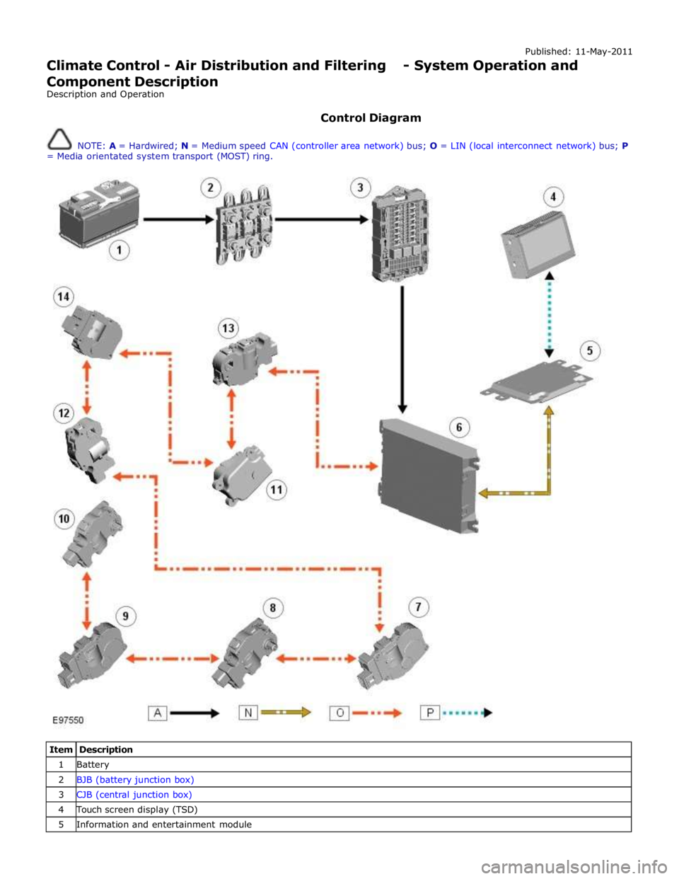
NOTE: A = Hardwired; N = Medium speed CAN (controller area network) bus; O = LIN (local interconnect network) bus; P
= Media orientated system transport (MOST) ring.
Item Description 1 Battery 2 BJB (battery junction box) 3 CJB (central junction box) 4 Touch screen display (TSD) 5 Information and entertainment module
Page 1693 of 3039
Touch screen display (TSD) 6 Integrated control panel 7 Information control module 8 ATC (automatic temperature control) module 9 Face/Feet distribution stepper motor 10 RH (right-hand) temperature blend stepper motor 11 LH (left-hand) temperature blend stepper motor 12 Windshield (defrost) distribution stepper motor 13 Blower control module 14 RJB (rear junction box) 15 Blower
System Operation
Operation of the heating and ventilation system is controlled by the ATC module. Refer to: Control Components (412-01 Climate Control, Description and Operation).
The system can be operated in automatic or manual mode, with temperature settings selected using the switches on the
integrated control panel.
When the engine is running, coolant is constantly circulated through the heater core by the engine coolant pump and the
auxiliary coolant pump. Where fitted, the auxiliary coolant pump is energized by the CJB on receipt of medium speed CAN bus signals from the ATC module. The CJB broadcasts auxiliary coolant pump status over the medium speed CAN bus for use by other vehicle systems.
The blower is supplied with power by the blower relay on the RJB and connected to ground via the blower control module. The blower control module regulates the voltage across the blower motor to control blower speed. The voltage set by the blower
control module is controlled by a PWM (pulse width modulation) signal from the ATC module. The ATC module uses a feedback signal from the blower control module to monitor blower speed.
Refer to: Control Components (412-01 Climate Control, Description and Operation).
Heater Assembly Component Description
The heater assembly controls the temperature and flow of air supplied to the air distribution ducts. The heater assembly is
mounted on the vehicle centerline, between the instrument panel and the engine bulkhead.
The heater assembly consists of a casing that contains an A/C (air conditioning) evaporator, a heater core, two air distribution
control doors and two temperature blend control doors. On 2.7L diesel vehicles, the heater assembly also contains an electric
booster heater.
Refer to: Electric Booster Heater (412-02 Auxiliary Climate Control, Description and Operation).
Mounted on the heater casing are four stepper motors. Each of the stepper motors is connected to either an air distribution
control door or a temperature blend control door.
The A/C evaporator is part of the A/C system. Refer to: Air Conditioning (412-01 Climate Control, Description and Operation).
The heater core provides the heat source to warm the air supplied to the passenger compartment. The heater core is an
aluminum two pass, fin and tube heat exchanger, and is installed across the width of the heater housing. Two aluminum tubes
attached to the heater core extend through the engine bulkhead and connect to the engine cooling system. For additional
information, refer to:
Engine Cooling (303-03A, Description and Operation),
Engine Cooling (303-03B Engine Cooling - V6 3.0L Petrol, Description and Operation), Engine Cooling (303-03C, Description and Operation).
Air Inlet Duct
The air inlet duct connects the fresh air inlet in the engine bulkhead to the heater assembly. The air inlet duct is installed
behind the instrument panel on the passenger side.
The air inlet duct consists of a casing that contains a pollen filter, an air inlet door, a blower and a blower control module. A
recirculation air inlet is incorporated into the casing. A servo motor is mounted on the casing and connected to the air inlet
door, to allow selection between fresh and recirculated air.
Refer to: Control Components (412-01 Climate Control, Description and Operation). The pollen filter is part of the air distribution and filtering system.
Refer to: Air Distribution and Filtering (412-01 Climate Control, Description and Operation).
The blower regulates the volume of air flowing through the air inlet duct to the heater assembly. The blower consists of an
open hub, centrifugal fan and an electric motor.
The blower control module regulates the power supply to the blower motor. The blower control module is installed in the air
Page 1706 of 3039
Climate Control - Control Components - Overview
Description and Operation
Overview Published: 11-May-2011
The climate control system is controlled by the ATC (automatic temperature control) module. It controls the heating and
ventilation system and the A/C (air conditioning) system to regulate the temperature, volume and distribution of air into the
passenger compartment. The system is a fully automatic dual zone system capable of maintaining individual temperature
levels selected for the LH (left-hand) and RH (right-hand) sides of the passenger compartment, up to a maximum differential
of approximately 3 ºC (5.4 ºF). Manual overrides for the system include inlet air source, blower speed and air distribution.
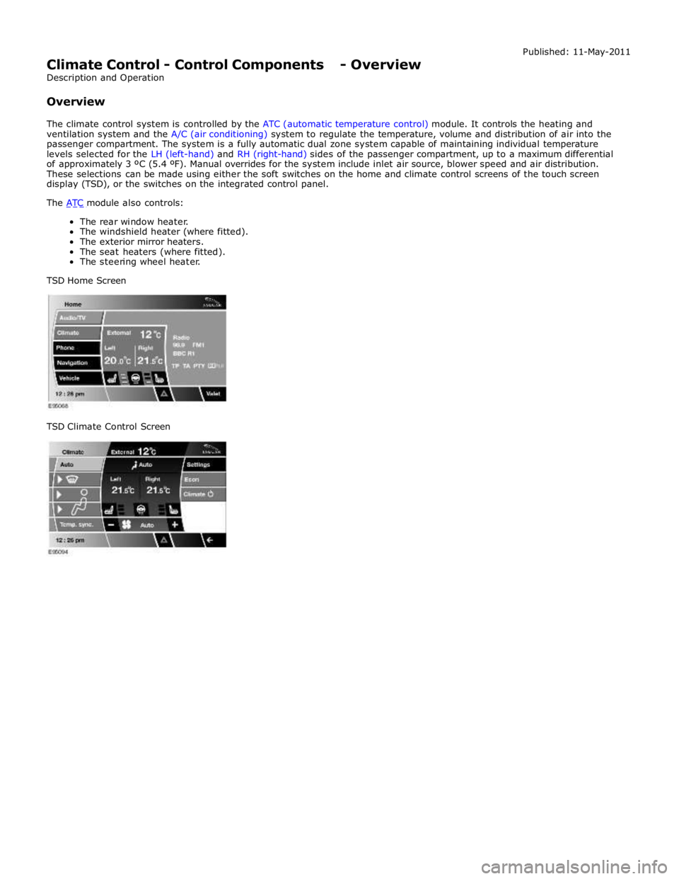
These selections can be made using either the soft switches on the home and climate control screens of the touch screen
display (TSD), or the switches on the integrated control panel.
The ATC module also controls: The rear window heater.
The windshield heater (where fitted).
The exterior mirror heaters.
The seat heaters (where fitted).
The steering wheel heater.
TSD Home Screen
TSD Climate Control Screen
Page 1709 of 3039
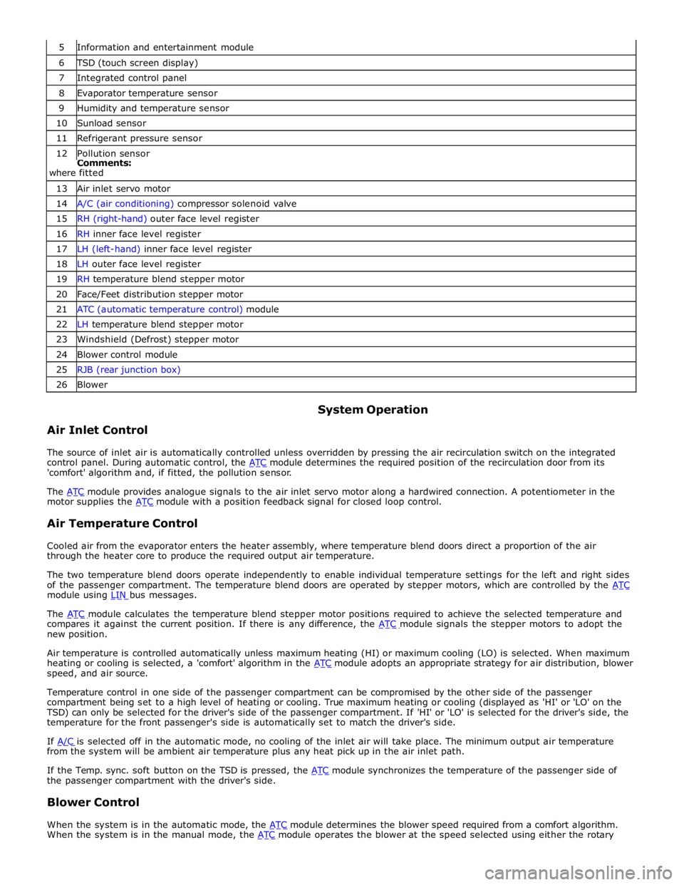
6 TSD (touch screen display) 7 Integrated control panel 8 Evaporator temperature sensor 9 Humidity and temperature sensor 10 Sunload sensor 11 Refrigerant pressure sensor 12 Pollution sensor Comments:
where fitted 13 Air inlet servo motor 14 A/C (air conditioning) compressor solenoid valve 15 RH (right-hand) outer face level register 16 RH inner face level register 17 LH (left-hand) inner face level register 18 LH outer face level register 19 RH temperature blend stepper motor 20 Face/Feet distribution stepper motor 21 ATC (automatic temperature control) module 22 LH temperature blend stepper motor 23 Windshield (Defrost) stepper motor 24 Blower control module 25 RJB (rear junction box) 26 Blower
Air Inlet Control System Operation
The source of inlet air is automatically controlled unless overridden by pressing the air recirculation switch on the integrated
control panel. During automatic control, the ATC module determines the required position of the recirculation door from its 'comfort' algorithm and, if fitted, the pollution sensor.
The ATC module provides analogue signals to the air inlet servo motor along a hardwired connection. A potentiometer in the motor supplies the ATC module with a position feedback signal for closed loop control.
Air Temperature Control
Cooled air from the evaporator enters the heater assembly, where temperature blend doors direct a proportion of the air
through the heater core to produce the required output air temperature.
The two temperature blend doors operate independently to enable individual temperature settings for the left and right sides
of the passenger compartment. The temperature blend doors are operated by stepper motors, which are controlled by the ATC module using LIN bus messages.
The ATC module calculates the temperature blend stepper motor positions required to achieve the selected temperature and compares it against the current position. If there is any difference, the ATC module signals the stepper motors to adopt the new position.
Air temperature is controlled automatically unless maximum heating (HI) or maximum cooling (LO) is selected. When maximum
heating or cooling is selected, a 'comfort' algorithm in the ATC module adopts an appropriate strategy for air distribution, blower speed, and air source.
Temperature control in one side of the passenger compartment can be compromised by the other side of the passenger
compartment being set to a high level of heating or cooling. True maximum heating or cooling (displayed as 'HI' or 'LO' on the
TSD) can only be selected for the driver's side of the passenger compartment. If 'HI' or 'LO' is selected for the driver's side, the
temperature for the front passenger's side is automatically set to match the driver's side.
If A/C is selected off in the automatic mode, no cooling of the inlet air will take place. The minimum output air temperature from the system will be ambient air temperature plus any heat pick up in the air inlet path.
If the Temp. sync. soft button on the TSD is pressed, the ATC module synchronizes the temperature of the passenger side of the passenger compartment with the driver's side.
Blower Control
When the system is in the automatic mode, the ATC module determines the blower speed required from a comfort algorithm. When the system is in the manual mode, the ATC module operates the blower at the speed selected using either the rotary
Page 1710 of 3039
control switch on the integrated control panel or the + and - soft buttons on the touch screen display (TSD). The ATC module also adjusts blower speed to compensate for the ram effect on inlet air produced by forward movement of the vehicle. As
vehicle speed and ram effect increases, blower motor speed is reduced, and vice versa.
Air Distribution Control
Two air distribution doors are used to direct air into the passenger compartment. The doors are operated by stepper motors,
which are controlled by the ATC module using LIN bus messages.
When the A/C system is in automatic mode, the ATC module automatically controls air distribution into the passenger compartment in line with its 'comfort' algorithm. Automatic control is overridden if any of the TSD air distribution soft buttons
are selected. Air distribution in the passenger compartment will remain as selected until the 'Auto' switch is pressed or a
different manual selection is made.
A/C Compressor Control
When A/C is selected the ATC module maintains the evaporator at an operating temperature that varies with the passenger compartment cooling requirements. If the requirement for cooled air decreases, the ATC module raises the evaporator operating temperature by reducing the flow of refrigerant provided by the A/C compressor. The ATC module closely controls the rate of temperature increase to avoid introducing moisture into the passenger compartment.
If the requirement for cooled air increases, the ATC module lowers the evaporator operating temperature by increasing the flow of refrigerant provided by the A/C compressor.
When A/C is off, the compressor current signal supplied by the ATC module holds the A/C compressor solenoid valve in the minimum flow position, effectively switching off the A/C function.
The ATC module incorporates limits for the operating pressure of the refrigerant system. If the system approaches the high pressure limit, the compressor current signal is progressively reduced until the system pressure decreases. If the system falls
below the low pressure limit, the compressor current signal is held at its lowest setting so that the A/C compressor is maintained at its minimum stroke. This avoids depletion of the lubricant from the A/C compressor.
A/C Compressor Torque
The ATC module transmits refrigerant pressure and A/C compressor current values to the ECM (engine control module) over the medium speed then high speed CAN bus, using the CJB as a gateway. The ECM uses these values to calculate the torque being used to drive the A/C compressor. The ECM compares the calculated value with its allowable value and if necessary forces the ATC module to inhibit the A/C compressor by transmitting the 'ACClutchInhibit' CAN message. This forces the ATC module to reduce the drive current to the A/C compressor solenoid valve, which reduces refrigerant flow. This in turn reduces the torque required to drive the A/C compressor.
By reducing the maximum A/C compressor torque, the ECM is able to reduce the load on the engine when it needs to maintain vehicle performance or cooling system integrity.
Cooling Fan Control
The ATC module determines the amount of condenser cooling required from the refrigerant pressure sensor, since there is a direct relationship between the temperature and pressure of the refrigerant. The cooling requirement is broadcast to the ECM on the medium speed CAN bus. The ECM then controls the temperature of the condenser using the cooling fan.
Programmed Defrost
The programmed defrost DEF switch is located on the integrated control panel. When the switch is pressed, the ATC module instigates the programmed defrost function. When selected, the ATC module configures the system as follows:
Automatic mode off.
A/C on. Selected temperature unchanged.
Air inlet set to fresh air.
Air distribution set to windshield.
Blower speed set to level 6.
Windshield heater (where fitted) and rear window heater on.
The programmed defrost function can be cancelled by one of the following:
Selecting any air distribution switch on the TSD.
Pressing the AUTO switch on the integrated control panel.
A second press of the DEF button.
Switching the ignition OFF.
The blower speed can be adjusted without terminating the programmed defrost function.
Rear Window Heater
Rear window heater operation is only enabled when the engine is running. The ATC module controls operation of the rear window heater using a relay in the RJB. When rear window heater operation is required, the ATC module broadcasts a message to the RJB on the medium speed CAN bus. On receipt of the message, the RJB energizes the relay by providing a ground path for the relay coil. This allows a battery feed to flow across the relay to power the rear window heater element.