Page 2063 of 3039

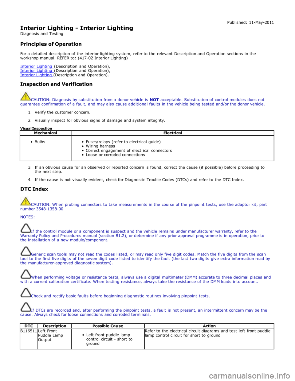
Interior Lighting - Interior Lighting
Diagnosis and Testing
Principles of Operation Published: 11-May-2011
For a detailed description of the interior lighting system, refer to the relevant Description and Operation sections in the
workshop manual. REFER to: (417-02 Interior Lighting)
Interior Lighting (Description and Operation), Interior Lighting (Description and Operation), Interior Lighting (Description and Operation).
Inspection and Verification
CAUTION: Diagnosis by substitution from a donor vehicle is NOT acceptable. Substitution of control modules does not
guarantee confirmation of a fault, and may also cause additional faults in the vehicle being tested and/or the donor vehicle.
1. Verify the customer concern.
2. Visually inspect for obvious signs of damage and system integrity.
Visual Inspection
Mechanical Electrical
Bulbs
Fuses/relays (refer to electrical guide)
Wiring harness
Correct engagement of electrical connectors
Loose or corroded connections
3. If an obvious cause for an observed or reported concern is found, correct the cause (if possible) before proceeding to
the next step.
4. If the cause is not visually evident, check for Diagnostic Trouble Codes (DTCs) and refer to the DTC Index.
DTC Index
CAUTION: When probing connectors to take measurements in the course of the pinpoint tests, use the adaptor kit, part
number 3548-1358-00
NOTES:
If the control module or a component is suspect and the vehicle remains under manufacturer warranty, refer to the
Warranty Policy and Procedures manual (section B1.2), or determine if any prior approval programme is in operation, prior to
the installation of a new module/component.
Generic scan tools may not read the codes listed, or may read only five digit codes. Match the five digits from the scan
tool to the first five digits of the seven digit code listed to identify the fault (the last two digits give extra information read by
the manufacturer-approved diagnostic system).
When performing voltage or resistance tests, always use a digital multimeter (DMM) accurate to three decimal places and
with a current calibration certificate. When testing resistance, always take the resistance of the DMM leads into account.
Check and rectify basic faults before beginning diagnostic routines involving pinpoint tests.
If DTCs are recorded and, after performing the pinpoint tests, a fault is not present, an intermittent concern may be the
cause. Always check for loose connections and corroded terminals.
DTC Description Possible Cause Action B116511
Left Front
Puddle Lamp
Output
Left front puddle lamp
control circuit - short to
ground Refer to the electrical circuit diagrams and test left front puddle
lamp control circuit for short to ground
Page 2067 of 3039

Published: 11-May-2011
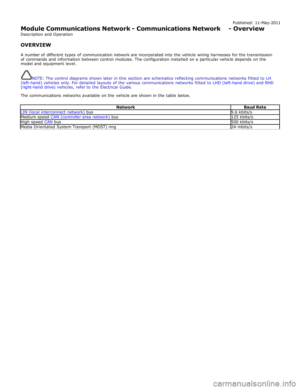
Module Communications Network - Communications Network - Overview
Description and Operation
OVERVIEW
A number of different types of communication network are incorporated into the vehicle wiring harnesses for the transmission
of commands and information between control modules. The configuration installed on a particular vehicle depends on the
model and equipment level.
NOTE: The control diagrams shown later in this section are schematics reflecting communications networks fitted to LH
(left-hand) vehicles only. For detailed layouts of the various communications networks fitted to LHD (left-hand drive) and RHD
(right-hand drive) vehicles, refer to the Electrical Guide.
The communications networks available on the vehicle are shown in the table below.
Network Baud Rate LIN (local interconnect network) bus 9.6 kbits/s Medium speed CAN (controller area network) bus 125 kbits/s High speed CAN bus 500 kbits/s Media Orientated System Transport (MOST) ring 24 mbits/s
Page 2068 of 3039
Published: 11-May-2011
Module Communications Network - Communications Network - System
Operation and Component Description
Description and Operation
Control Diagram
NOTE:
CONTROL DIAGRAM - LIN BUS - SHEET 1 OF 2
Item Description O = LIN (local interconnect network) bus 1 CJB (central junction box) 2 Battery backed sounder 3 Intrusion detection module
Page 2069 of 3039
5 RJB (rear junction box) 6 Battery monitoring system module 7 Rear view camera 8 TCM (transmission control module) 9 Generator 10 Driver's door switch pack 11 Rear door control module 12 Driver's door control module 13 ECM (engine control module) 14 Electronic transmission selector 15 Driver's seat module 16 Driver's seat switch pack 17 Rear door control module 18 Front passenger door control module 19 Clockspring 20 Audio and telephone steering wheel switches 21 Instrument cluster 22 Start control module
Page 2070 of 3039
O = LIN bus 1 ATC (automatic temperature control) module 2 Stepper motor - Windshield defrost 3 Stepper motor - Face/feet distribution 4 Stepper motor - LH (left-hand) temperature blend 5 Stepper motor - RH (right-hand) temperature blend 6 Electric booster heater 7 Stepper motor - RH outer face level vent 8 Stepper motor - RH inner face level vent 9 Stepper motor - LH inner face level vent 10 Stepper motor - LH outer face level vent CONTROL DIAGRAM - LIN BUS - SHEET 2 OF 2
www.JagDocs.com
Page 2071 of 3039
N = Medium speed CAN (controller area network) bus 1 Parking aid module 2 RJB 3 Keyless vehicle module 4 RH blind spot monitoring module 5 Driver's seat module 6 Front seat climate control module 7 Information control module 8 ATC module 9 CJB 10 Diagnostic socket 11 Instrument cluster 12 Integrated control panel 13 Front passenger door control module
Page 2072 of 3039
Tire Pressure Monitoring System (TPMS) module 15 Driver's door control module 16 LH blind spot monitoring module CONTROL DIAGRAM - HIGH SPEED CAN BUS
Item Description D = High speed CAN bus 1 Electric steering column lock 2 Instrument cluster 3 Diagnostic socket 4 Adaptive speed control module 5 Electronic transmission selector 6 Occupant classification system control module 7 Headlamp leveling module 8 ABS (anti-lock brake system) module
Page 2073 of 3039
10 TCM 11 Pedestrian protection system control module 12 Electric park brake module 13 RCM (restraints control module) 14 Adaptive damping control module CONTROL DIAGRAM - MOST RING
Item Description P = MOST ring 1 Entertainment system control module 2 Software download socket 3 Touch Screen Display (TSD) 4 Portable audio interface 5 Bluetooth® telephone module