2010 JAGUAR XFR park brake
[x] Cancel search: park brakePage 664 of 3039

Parking Brake and Actuation - Parking Brake Release Actuator
Removal and Installation
Removal Published: 06-May-2014
WARNING: Failure to release the tension and calibrate the electric parking brake during rear parking brake related service
procedures, could cause the parking brake to function incorrectly or become inoperative.
1. Refer to: Parking Brake Cable Tension Release (206-05 Parking Brake and Actuation, General Procedures).
2. WARNING: Make sure to support the vehicle with axle stands.
Raise and support the vehicle.
3. Remove the differential case.
Refer to: Differential Case - TDV6 3.0L Diesel /V8 5.0L Petrol/V8 S/C 5.0L Petrol (205-02 Rear Drive Axle/Differential, Removal and Installation).
Refer to: Differential Case - TD4 2.2L Diesel/TDV6 3.0L Diesel (205-02,
Removal and Installation).
4. Torque: 7 Nm
Page 666 of 3039

7.
Installation
1. To install, reverse the removal procedure.
2. CAUTION: Make sure the wiring harness is correctly routed
to avoid contact with the halfshaft. Failure to follow this
instruction may result in damage to the component.
3. CAUTION: Calibrate the electric park brake using Jaguar approved
diagnostic system. If the Jaguar approved diagnostic system is not
available disconnect the battery for approximately 30 seconds, the
vehicle will then prompt the driver to carry out the calibration procedure
as per the vehicle hand book on re-connection.
Calibrate the electric parking brake (EPB) using the diagnostic tool.
Page 694 of 3039

7 Brake fluid level switch 8 LH rear wheel speed sensor 9 RH rear wheel speed sensor 10 RJB (rear junction box) 11 High mounted stop lamp 12 LH stop lamp 13 RH stop lamp 14 Diagnostic socket 15 TCM (transmission control module) 16 Electronic parking brake module 17 ECM (engine control module) 18 Instrument cluster 19 ABS (anti-lock brake system) module 20 JaguarDrive selector module 21 Adaptive damping control module 22 Adaptive speed control module 23 Yaw rate and lateral acceleration sensor 24 Roof opening panel motor/module 25 Brake booster vacuum sensor (3.0L vehicles only) 26 Steering angle sensor
Anti-Lock Brake System System Operation
ABS controls the speed of all road wheels to ensure optimum wheel slip when braking at the adhesion limit. The wheels are prevented from locking to retain effective steering control of the vehicle.
The brake pressures are modulated separately for each wheel. Rear brake pressures are controlled to maintain rear stability on
split friction surfaces.
Dynamic Stability Control
DSC (dynamic stability control) uses brakes and powertrain torque control to assist in maintaining the yaw stability of the
vehicle. While the ignition is energized the DSC function is permanently enabled, unless selected off using the DSC switch.
DSC enhances driving safety in abrupt maneuvers and in under-steer or over-steer situations that may occur in a bend. The
ABS module monitors the yaw rate and lateral acceleration of the vehicle, steering input and individual wheel speeds, then selectively applies individual brakes and signals for powertrain torque adjustments to reduce under-steer or over-steer
conditions.
In general:
In an under-steer situation the inner wheels are braked to counteract the yaw movement towards the outer edge of the
bend.
In an over-steer situation the outer wheels are braked to prevent the rear end of the vehicle from pushing towards the
outer edge of the bend.
The ABS module monitors the tracking stability of the vehicle using inputs from the wheel speed sensors, the steering angle sensor, and the yaw rate and lateral acceleration sensor. The tracking stability is compared with stored target data. Whenever
the tracking stability deviates from the target data, the ABS module intervenes by applying the appropriate control strategy. The following interactions occur in an intervention situation:
High speed CAN signal to the ECM, to reduce engine torque. Application of braking to the appropriate corner of the vehicle.
Trac DSC
TracDSC is an alternative setting of DSC with reduced system interventions. With TracDSC engaged, traction may be somewhat
increased, although stability may be reduced compared to normal DSC. TracDSC is intended for use only on dry tarmac, by
suitably experienced drivers and should not be selected for other surfaces or by drivers with insufficient skill and training to
operate the vehicle safely with the TracDSC function engaged.
The less restrictive TracDSC setting may be preferred, for example, by expert drivers engaged in high performance driving on
dry Tarmac surfaces such as tracks and circuits.
Switching between DSC and Trac DSC:
Page 813 of 3039
Component Tests
Engine Oil Leaks
NOTE: Before installing new gaskets or oil seals, make sure that the fault is clearly established.
If the oil leak cannot be identified clearly by a visual inspection, carry out an Ultraviolet test:
Fluorescent Oil Additive Method
1. Clean the engine with a suitable cleaning fluid (brake cleaner).
2. Drain the engine oil and refill with recommended oil, premixed with Diesel Engine Oil Dye or equivalent. Use a minimum
14.8 ml (0.5 ounce) to a maximum 29.6 ml (1 ounce) of fluorescent additive to all engines. If oil is not premixed,
fluorescent additive must first be added to the crankcase.
3. Run engine for 15 minutes. Stop the engine and inspect all seal and gasket areas for leaks using a 12 Volt Master UV
Diagnostic Inspection Kit or equivalent. A clear bright yellow or orange area will identify leak. For extremely small
leaks, several hours may be required for the leak to appear.
4. As necessary, pressurize the main oil gallery system to locate leaks due to incorrectly sealed, loose or cocked plugs. If
the flywheel bolts leak oil, look for sealer on the threads.
5. Repair all leaks as necessary.
Compression Test General Remarks
NOTES:
Removing fuses and disconnecting electrical components may cause the Engine Control Module (ECM) to log Diagnostic
Trouble Codes (DTCs). After the measurements have been carried out, DTCs should be cleared from memory by connecting to
the Manufacturer Approved Diagnostic System.
Only check the compression pressure with the valves set to the prescribed clearance (if this can be adjusted).
The compression pressure should be checked with the engine at normal operating temperature.
Check the Compression Pressure
WARNING: Move gear selector lever to 'P' position. Failure to follow this instruction may result in personal injury.
1. Remove the fuel pump relay.
2. Start the engine - the engine will start, run for a few seconds then stall.
3. Remove the spark plugs.
4. Install the compression tester.
5. Install an auxiliary starter switch in the starting circuit. With the ignition switch OFF, using the auxiliary starter switch,
crank the engine a minimum of five compression strokes and record the highest reading. Note the approximate number
of compression strokes required to obtain the highest reading.
6. Repeat the test on each cylinder, cranking the engine approximately the same number of compression strokes.
7. Install the removed components in reverse order, observing the specified tightening torques.
8. Clear all DTCs from the ECM.
Interpretation of the Results
NOTE: Due to the possibility of loose carbon that has become trapped between the valve face and seat effecting the
pressure readings, when carrying out a compression test and cylinders are found to have low pressures, install the spark plugs,
road test the vehicle and re-test the suspect cylinders. If the correct pressures are restored, no further action is required.
The indicated compression pressures are considered within specification if the lowest reading cylinder is within 75% of the
highest reading.
If the cylinder pressures are found to be low, carry out a leakdown test to determine the location of the fault (if any leakback
can be heard through the engine breather system suspect the piston rings, if any leakback can be heard through the inlet
system suspect the inlet valve or seat, if any leakback can be heard through the exhaust manifold suspect the exhaust valve
or seat. If the measurements for two cylinders next to each other are both too low then it is very likely that the cylinder head
gasket between them is burnt through. This can also be recognized by traces of engine oil in the coolant and/or coolant in the
Page 816 of 3039
9. WEAK VALVE SPRINGS: When the needle oscillation becomes more violent as engine RPM is increased, weak valve
springs are indicated. The reading at idle could be relatively steady.
10. LATE VALVE TIMING: A steady but low reading could be caused by late valve timing.
11.
IGNITION TIMING RETARDED: Retarded ignition timing will produce a steady but somewhat low reading.
12.
INSUFFICIENT SPARK PLUG GAP: When spark plugs are gapped too close, a regular, small pulsation of the needle can
occur.
13. INTAKE LEAK: A low, steady reading can be caused by an intake manifold or throttle body gasket leak.
14.
BLOWN HEAD GASKET: A regular drop of fair magnitude can be caused by a blown head gasket or warped cylinder head
to cylinder block surface.
15.
RESTRICTED EXHAUST SYSTEM: When the engine is first started and is idled, the reading may be normal, but as the
engine RPM is increased, the back pressure caused by a clogged muffler, kinked tail pipe or other concerns will cause
the needle to slowly drop to 0 kPa (0 in-Hg). The needle then may slowly rise. Excessive exhaust clogging will cause
the needle to drop to a low point even if the engine is only idling.
When vacuum leaks are indicated, search out and correct the cause. Excess air leaking into the system will upset the fuel
mixture and cause concerns such as rough idle, missing on acceleration or burned valves. If the leak exists in an accessory
such as the power brake booster, the unit will not function correctly. Always repair vacuum leaks.
Engine Oil Pressure Check
NOTE: Prior to checking the engine oil pressure, a road test of 6 miles (10 kilometres), must be carried out. Do not
attempt to attain engine normal operating temperature by allowing the engine to idle.
1. Disconnect the battery ground cable. Refer to section 414-00 - Charging System - General Information of the workshop
manual
2. WARNINGS:
The spilling of hot engine oil is unavoidable during this procedure, care must be taken to prevent scalding.
Wear protective gloves.
Remove the engine oil filter element
REFER to: Oil Filter Element (303-01C Engine - V8 5.0L Petrol, Removal and Installation).
NOTE: Ensure the oil filter element is not contaminated during this procedure
3. Install the oil filter element into special tool (Oil filter adapter number 303-1451)
4. Install the special tool (Oil filter adapter number 303-1451) to the engine. Torque: 25 Nm
5. Install the special tool (Oil pressure testing gauge, 303-871) and tighten the union
6. Connect the battery ground cable
7. Refer to owner hand book, check and top-up the engine oil if required
8. Start and run the engine
9. Note the oil pressure readings with the engine running at idle and 3500 RPM
10.
Turn off the engine
11.
Disconnect the battery ground cable
12. Remove the special tools
1. Clean the components
13.
Install the engine oil filter element
REFER to: Oil Filter Element (303-01C Engine - V8 5.0L Petrol, Removal and Installation).
NOTE: Ensure the oil filter element is not contaminated during this procedure
14.
Connect the battery ground cable
15. Refer to owner hand book, check and top-up the engine oil if required
www.JagDocs.com
Page 1266 of 3039
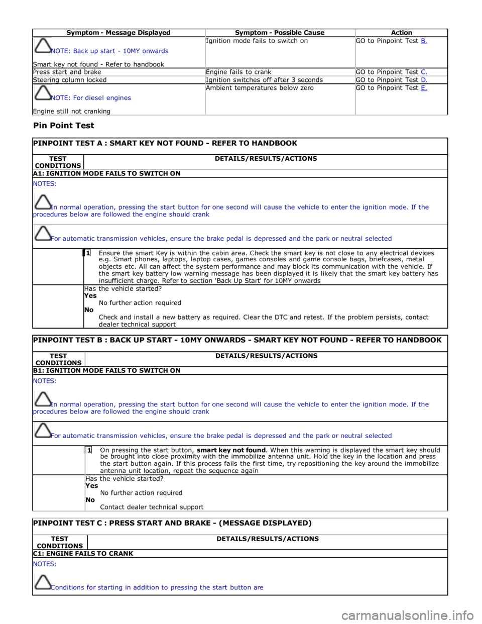
Symptom - Message Displayed Symptom - Possible Cause Action NOTE: Back up start - 10MY onwards
Smart key not found - Refer to handbook Ignition mode fails to switch on GO to Pinpoint Test B. Press start and brake Engine fails to crank GO to Pinpoint Test C. Steering column locked Ignition switches off after 3 seconds GO to Pinpoint Test D. NOTE: For diesel engines Engine still not cranking Ambient temperatures below zero GO to Pinpoint Test E.
Pin Point Test
PINPOINT TEST A : SMART KEY NOT FOUND - REFER TO HANDBOOK TEST
CONDITIONS DETAILS/RESULTS/ACTIONS A1: IGNITION MODE FAILS TO SWITCH ON NOTES:
In normal operation, pressing the start button for one second will cause the vehicle to enter the ignition mode. If the
procedures below are followed the engine should crank
For automatic transmission vehicles, ensure the brake pedal is depressed and the park or neutral selected 1 Ensure the smart Key is within the cabin area. Check the smart key is not close to any electrical devices e.g. Smart phones, laptops, laptop cases, games consoles and game console bags, briefcases, metal
objects etc. All can affect the system performance and may block its communication with the vehicle. If
the smart key battery low warning message has been displayed it is likely that the smart key battery has
insufficient charge. Refer to section 'Back Up Start' for 10MY onwards Has the vehicle started? Yes
No further action required
No
Check and install a new battery as required. Clear the DTC and retest. If the problem persists, contact
dealer technical support
PINPOINT TEST B : BACK UP START - 10MY ONWARDS - SMART KEY NOT FOUND - REFER TO HANDBOOK TEST
CONDITIONS DETAILS/RESULTS/ACTIONS B1: IGNITION MODE FAILS TO SWITCH ON NOTES:
In normal operation, pressing the start button for one second will cause the vehicle to enter the ignition mode. If the
procedures below are followed the engine should crank
For automatic transmission vehicles, ensure the brake pedal is depressed and the park or neutral selected 1 On pressing the start button, smart key not found. When this warning is displayed the smart key should be brought into close proximity with the immobilize antenna unit. Hold the key in the location and press
the start button again. If this process fails the first time, try repositioning the key around the immobilize
antenna unit location, repeat the sequence again Has the vehicle started? Yes
No further action required
No
Contact dealer technical support
PINPOINT TEST C : PRESS START AND BRAKE - (MESSAGE DISPLAYED) TEST
CONDITIONS DETAILS/RESULTS/ACTIONS C1: ENGINE FAILS TO CRANK NOTES:
Conditions for starting in addition to pressing the start button are
Page 1267 of 3039
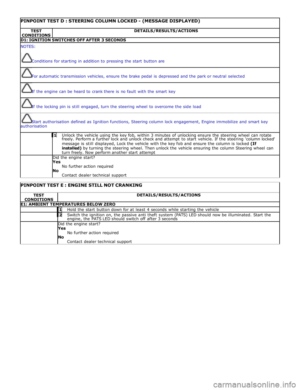
PINPOINT TEST D : STEERING COLUMN LOCKED - (MESSAGE DISPLAYED) TEST
CONDITIONS DETAILS/RESULTS/ACTIONS D1: IGNITION SWITCHES OFF AFTER 3 SECONDS NOTES:
Conditions for starting in addition to pressing the start button are
For automatic transmission vehicles, ensure the brake pedal is depressed and the park or neutral selected
If the engine can be heard to crank there is no fault with the smart key
If the locking pin is still engaged, turn the steering wheel to overcome the side load
Start authorisation defined as Ignition functions, Steering column lock engagement, Engine immobilize and smart key
authorisation 1 Unlock the vehicle using the key fob, within 3 minutes of unlocking ensure the steering wheel can rotate freely. Perform a further lock and unlock check and attempt to start vehicle. If the steering 'column locked'
message is still displayed, Lock the vehicle with the key fob and ensure the column is locked (If
installed) by turning the steering wheel. Then unlock the vehicle ensuring the column Steering wheel can
turn freely. Now perform another start attempt Did the engine start?
Yes
No further action required
No
Contact dealer technical support
PINPOINT TEST E : ENGINE STILL NOT CRANKING TEST
CONDITIONS DETAILS/RESULTS/ACTIONS E1: AMBIENT TEMPERATURES BELOW ZERO 1 Hold the start button down for at least 4 seconds while starting the vehicle 2 Switch the ignition on, the passive anti theft system (PATS) LED should now be illuminated. Start the engine, the PATS LED should switch off after 3 seconds Did the engine start? Yes
No further action required
No
Contact dealer technical support
Page 1422 of 3039
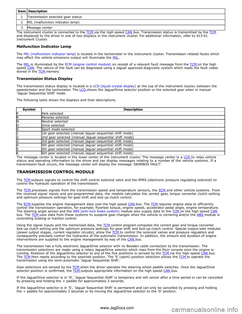
1 Transmission selected gear status 2 MIL (malfunction indicator lamp) 3 Message center The instrument cluster is connected to the TCM via the high speed CAN bus. Transmission status is transmitted by the TCM and displayed to the driver in one of two displays in the instrument cluster. For additional information, refer to 413-01
Instrument Cluster.
Malfunction Indicator Lamp
The MIL (malfunction indicator lamp) is located in the tachometer in the instrument cluster. Transmission related faults which
may affect the vehicle emissions output will illuminate the MIL.
The MIL is illuminated by the ECM (engine control module) on receipt of a relevant fault message from the TCM on the high speed CAN. The nature of the fault can be diagnosed using a Jaguar approved diagnostic system which reads the fault codes stored in the TCM memory.
Transmission Status Display
The transmission status display is located in a LCD (liquid crystal display) at the top of the instrument cluster, between the
speedometer and the tachometer. The LCD shows the JaguarDrive selector position or the selected gear when in manual 'Jaguar Sequential Shift' mode.
The following table shows the displays and their descriptions.
Symbol Description P Park selected R Reverse selected N Neutral selected D Drive selected S Sport mode selected 1 1st gear selected (manual Jaguar sequential shift mode) 2 2nd gear selected (manual Jaguar sequential shift mode) 3 3rd gear selected (manual Jaguar sequential shift mode) 4 4th gear selected (manual Jaguar sequential shift mode) 5 5th gear selected (manual Jaguar sequential shift mode) 6 6th gear selected (manual Jaguar sequential shift mode) The message center is located in the lower center of the instrument cluster. The message center is a LCD to relay vehicle status and operating information to the driver and can display messages relating to a number of the vehicle systems. If a
transmission fault occurs, the message center will display the message 'GEARBOX FAULT'.
TRANSMISSION CONTROL MODULE
The TCM outputs signals to control the shift control solenoid valve and the EPRS (electronic pressure regulating solenoid) to control the hydraulic operation of the transmission.
The TCM processes signals from the transmission speed and temperature sensors, the ECM and other vehicle systems. From the received signal inputs and pre-programmed data, the module calculates the correct gear, torque converter clutch setting
and optimum pressure settings for gear shift and lock-up clutch control.
The ECM supplies the engine management data over the high speed CAN bus. The TCM requires engine data to efficiently control the transmission operation, for example; flywheel torque, engine speed, accelerator pedal angle, engine temperature.
The steering angle sensor and the ABS (anti-lock brake system) module also supply data to the TCM on the high speed CAN bus. The TCM uses data from these systems to suspend gear changes when the vehicle is cornering and/or the ABS module is controlling braking or traction control.
Using the signal inputs and the memorized data, the TCM control program computes the correct gear and torque converter lock-up clutch setting and the optimum pressure settings for gear shift and lock-up clutch control. Special output-side modules
(power output stages, current regulator circuits), allow the TCM to control the solenoid valves and pressure regulators and consequently precisely control the hydraulics of the automatic transmission. In addition, the amount and duration of engine
interventions are supplied to the engine management by way of the CAN bus.
The transmission has a fully electronic JaguarDrive selector with no Bowden cable connection to the transmission. The
transmission selections are made using a rotary JaguarDrive selector which rises from the floor console once the engine is
running. Rotation of the JaguarDrive selector to any of the five positions is sensed by the TCM via the high speed CAN bus. The TCM then reacts according to the selected position. The 'S' (sport) position selection allows the TCM to operate the transmission using the semi-automatic 'Jaguar Sequential Shift'.
Gear selections are sensed by the TCM when the driver operates the steering wheel paddle switches. Once the JaguarDrive selector position is confirmed, the TCM outputs appropriate information on the high speed CAN bus.
If the JaguarDrive selector is in 'D', 'Jaguar Sequential Shift' is temporary and will cancel after a time period or can be cancelled
by pressing and holding the + paddle for approximately 2 seconds.
If the JaguarDrive selector is in 'S', 'Jaguar Sequential Shift' is permanent and can only be cancelled by pressing and holding
the + paddle for approximately 2 seconds or by moving the JaguarDrive selector to the 'D' position.
www.JagDocs.com