2010 JAGUAR XFR park brake
[x] Cancel search: park brakePage 2091 of 3039

DTC Description Possible Cause Action B1D2711
Heater Coolant
Pump
Heater coolant pump control
circuit - short to ground Carry out any pinpoint tests associated with this DTC
using the manufacturer approved diagnostic system.
Refer to the electrical circuit diagrams and check heater
coolant pump control circuit for short to ground B1D2713
Heater Coolant
Pump
Heater coolant pump control
circuit - open circuit Carry out any pinpoint tests associated with this DTC
using the manufacturer approved diagnostic system.
Refer to the electrical circuit diagrams and check heater
coolant pump control circuit for open circuit B1D9796 Tilt Sensor
Component internal failure Suspect the battery backed sounder, check and install a
new battery backed sounder as required P057112
Brake Switch A
Circuit
Footbrake switch circuit - short
to power Refer to the electrical circuit diagrams and check
footbrake switch circuit for short to power P080111
Reverse Inhibit
Control Circuit
Electrochromic rear view mirror,
reverse inhibit circuit - short to
ground Carry out any pinpoint tests associated with this DTC
using the manufacturer approved diagnostic system.
Refer to the electrical circuit diagrams and check
electrochromic rear view mirror, reverse inhibit circuit for
short to ground P080112
Reverse Inhibit
Control Circuit
Electrochromic rear view mirror,
reverse inhibit circuit - short to
power Refer to the electrical circuit diagrams and check
electrochromic rear view mirror, reverse inhibit circuit for
short to power P080113
Reverse Inhibit
Control Circuit
Electrochromic rear view mirror,
reverse inhibit circuit - open
circuit Refer to the electrical circuit diagrams and check
electrochromic rear view mirror, reverse inhibit circuit for
open circuit P085013
Park/Neutral Switch
Input Circuit
Park/Neutral signal circuit -
open circuit Refer to the electrical circuit diagrams and check
Park/Neutral signal circuit for open circuit P162413 Anti-theft System
RJB anti-theft signal circuit -
open circuit Refer to the electrical circuit diagrams and check RJB
anti-theft signal circuit for open circuit P254F13
Engine Hood Switch
Circuit/Open
Hood ajar switch signal circuit -
open circuit Refer to the electrical circuit diagrams and check hood
ajar switch signal circuit for open circuit U001988
Low Speed CAN
Communication Bus
Bus OFF Carry out any pinpoint tests associated with this DTC
using the manufacturer approved diagnostic system. U014200
Lost
Communication
With Body Control
Module "B"
No sub type information Carry out any pinpoint tests associated with this DTC
using the manufacturer approved diagnostic system. U015500
Lost
Communication
With Instrument
Panel Cluster (IPC)
Control Module
No sub type information Carry out any pinpoint tests associated with this DTC
using the manufacturer approved diagnostic system. U015600
Lost
Communication
With Information
Center "A"
No sub type information Carry out any pinpoint tests associated with this DTC
using the manufacturer approved diagnostic system. U016400
Lost
Communication
With HVAC Control
Module
No sub type information Carry out any pinpoint tests associated with this DTC
using the manufacturer approved diagnostic system. U016800
Lost
Communication
With Vehicle
Security Control
Module
No sub type information Check power and ground supplies to vehicle security
module U019900
Lost
Communication
With "Door Control
Module A"
No sub type information Carry out any pinpoint tests associated with this DTC
using the manufacturer approved diagnostic system. U020000
Lost
Communication
With "Door Control
Module B"
No sub type information Carry out any pinpoint tests associated with this DTC
using the manufacturer approved diagnostic system.
Page 2141 of 3039

Anti-Theft - Passive - Anti-Theft - Passive - Overview
Description and Operation
Overview Published: 11-May-2011
The PATS (passive anti-theft system) prevents the vehicle's engine from being started by unauthorized persons.
Engine starting is prevented by inhibiting the fuel, engine (spark, injectors and crank) and ignition systems from operating.
This is achieved by using a uniquely coded Smart Key and an encoded data exchange between multiple control modules.
The system is automatic and requires no input from the driver.
The engine start system is initiated when the encoded data between the Smart Key and vehicle control modules is verified.
The engine can then be started when the drive selector is in the 'Park' position, and the start/stop switch and the brake pedal
are pressed simultaneously.
Page 2143 of 3039

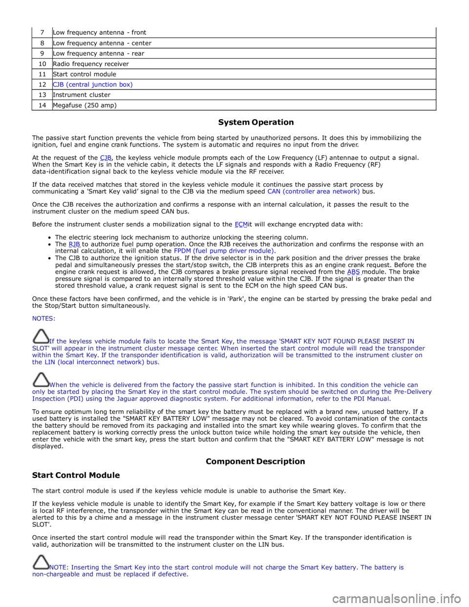
7 Low frequency antenna - front 8 Low frequency antenna - center 9 Low frequency antenna - rear 10 Radio frequency receiver 11 Start control module 12 CJB (central junction box) 13 Instrument cluster 14 Megafuse (250 amp)
System Operation
The passive start function prevents the vehicle from being started by unauthorized persons. It does this by immobilizing the
ignition, fuel and engine crank functions. The system is automatic and requires no input from the driver.
At the request of the CJB, the keyless vehicle module prompts each of the Low Frequency (LF) antennae to output a signal. When the Smart Key is in the vehicle cabin, it detects the LF signals and responds with a Radio Frequency (RF)
data-identification signal back to the keyless vehicle module via the RF receiver.
If the data received matches that stored in the keyless vehicle module it continues the passive start process by
communicating a 'Smart Key valid’ signal to the CJB via the medium speed CAN (controller area network) bus.
Once the CJB receives the authorization and confirms a response with an internal calculation, it passes the result to the
instrument cluster on the medium speed CAN bus.
Before the instrument cluster sends a mobilization signal to the ECMit will exchange encrypted data with: The electric steering lock mechanism to authorize unlocking the steering column.
The RJB to authorize fuel pump operation. Once the RJB receives the authorization and confirms the response with an internal calculation, it will enable the FPDM (fuel pump driver module).
The CJB to authorize the ignition status. If the drive selector is in the park position and the driver presses the brake
pedal and simultaneously presses the start/stop switch, the CJB interprets this as an engine crank request. Before the
engine crank request is allowed, the CJB compares a brake pressure signal received from the ABS module. The brake pressure signal is compared to an internally stored threshold value within the CJB. If the signal is greater than the
stored threshold value, a crank request signal is sent to the ECM on the high speed CAN bus.
Once these factors have been confirmed, and the vehicle is in 'Park', the engine can be started by pressing the brake pedal and
the Stop/Start button simultaneously.
NOTES:
If the keyless vehicle module fails to locate the Smart Key, the message 'SMART KEY NOT FOUND PLEASE INSERT IN
SLOT' will appear in the instrument cluster message center. When inserted the start control module will read the transponder
within the Smart Key. If the transponder identification is valid, authorization will be transmitted to the instrument cluster on
the LIN (local interconnect network) bus.
When the vehicle is delivered from the factory the passive start function is inhibited. In this condition the vehicle can
only be started by placing the Smart Key in the start control module. The system should be switched on during the Pre-Delivery
Inspection (PDI) using the Jaguar approved diagnostic system. For additional information, refer to the PDI Manual.
To ensure optimum long term reliability of the smart key the battery must be replaced with a brand new, unused battery. If a
used battery is installed the "SMART KEY BATTERY LOW" message may not be cleared. To avoid contamination of the contacts
the battery should be removed from its packaging and installed into the smart key while wearing gloves. To confirm that the
replacement battery is working correctly press the unlock button twice while holding the smart key outside the vehicle, then
enter the vehicle with the smart key, press the start button and confirm that the "SMART KEY BATTERY LOW" message is not
displayed.
Start Control Module Component Description
The start control module is used if the keyless vehicle module is unable to authorise the Smart Key.
If the keyless vehicle module is unable to identify the Smart Key, for example if the Smart Key battery voltage is low or there
is local RF interference, the transponder within the Smart Key can be read in the conventional manner. The driver will be
alerted to this by a chime and a message in the instrument cluster message center 'SMART KEY NOT FOUND PLEASE INSERT IN
SLOT'.
Once inserted the start control module will read the transponder within the Smart Key. If the transponder identification is
valid, authorization will be transmitted to the instrument cluster on the LIN bus.
NOTE: Inserting the Smart Key into the start control module will not charge the Smart Key battery. The battery is
non-chargeable and must be replaced if defective.
Page 2151 of 3039

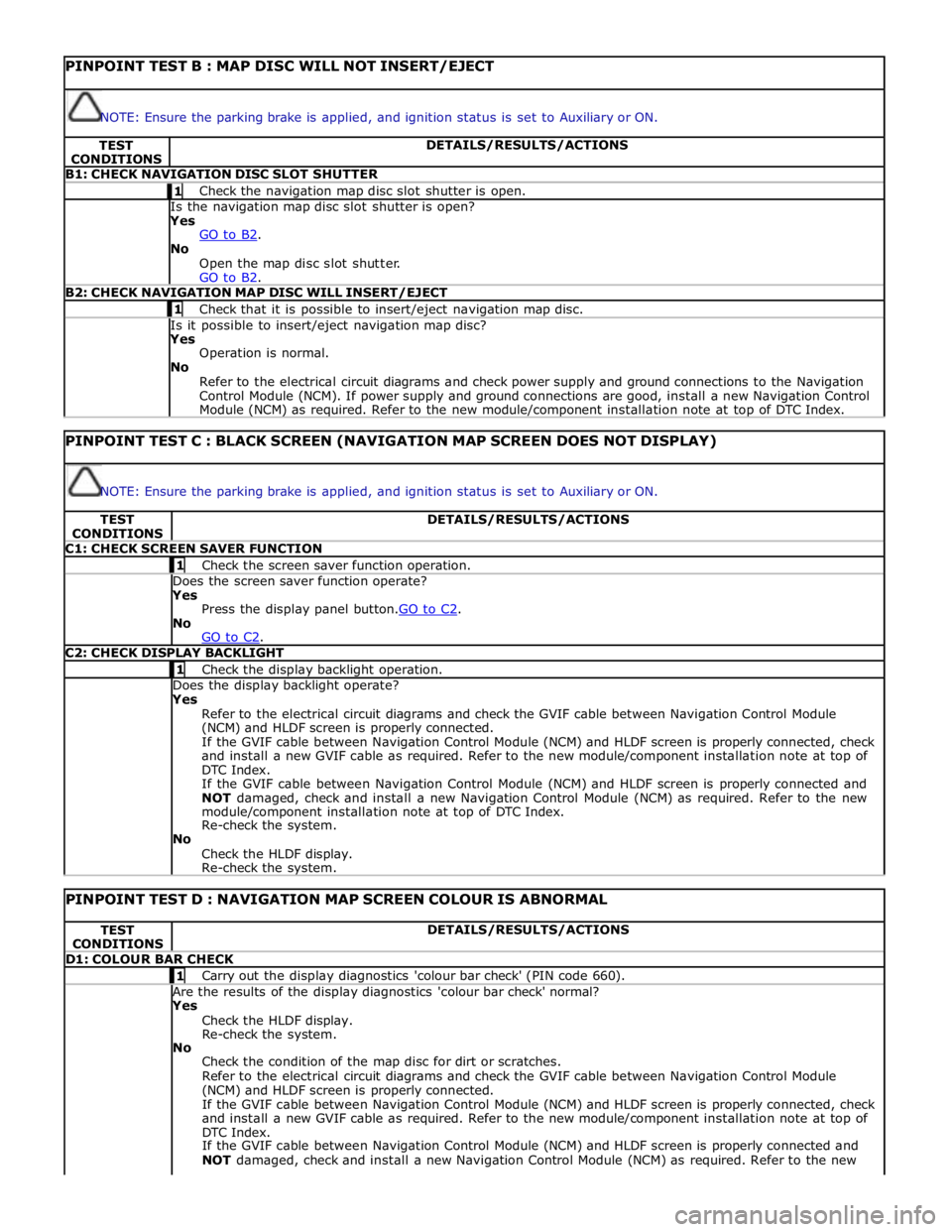
PINPOINT TEST B : MAP DISC WILL NOT INSERT/EJECT
NOTE: Ensure the parking brake is applied, and ignition status is set to Auxiliary or ON. TEST
CONDITIONS DETAILS/RESULTS/ACTIONS B1: CHECK NAVIGATION DISC SLOT SHUTTER 1 Check the navigation map disc slot shutter is open. Is the navigation map disc slot shutter is open? Yes
GO to B2. No
Open the map disc slot shutter.
GO to B2. B2: CHECK NAVIGATION MAP DISC WILL INSERT/EJECT 1 Check that it is possible to insert/eject navigation map disc. Is it possible to insert/eject navigation map disc? Yes
Operation is normal.
No
Refer to the electrical circuit diagrams and check power supply and ground connections to the Navigation
Control Module (NCM). If power supply and ground connections are good, install a new Navigation Control
Module (NCM) as required. Refer to the new module/component installation note at top of DTC Index.
PINPOINT TEST C : BLACK SCREEN (NAVIGATION MAP SCREEN DOES NOT DISPLAY)
NOTE: Ensure the parking brake is applied, and ignition status is set to Auxiliary or ON. TEST
CONDITIONS DETAILS/RESULTS/ACTIONS C1: CHECK SCREEN SAVER FUNCTION 1 Check the screen saver function operation. Does the screen saver function operate? Yes
Press the display panel button.GO to C2. No
GO to C2. C2: CHECK DISPLAY BACKLIGHT 1 Check the display backlight operation. Does the display backlight operate? Yes
Refer to the electrical circuit diagrams and check the GVIF cable between Navigation Control Module
(NCM) and HLDF screen is properly connected.
If the GVIF cable between Navigation Control Module (NCM) and HLDF screen is properly connected, check
and install a new GVIF cable as required. Refer to the new module/component installation note at top of
DTC Index.
If the GVIF cable between Navigation Control Module (NCM) and HLDF screen is properly connected and
NOT damaged, check and install a new Navigation Control Module (NCM) as required. Refer to the new
module/component installation note at top of DTC Index.
Re-check the system.
No
Check the HLDF display.
Re-check the system.
PINPOINT TEST D : NAVIGATION MAP SCREEN COLOUR IS ABNORMAL TEST
CONDITIONS DETAILS/RESULTS/ACTIONS D1: COLOUR BAR CHECK 1 Carry out the display diagnostics 'colour bar check' (PIN code 660). Are the results of the display diagnostics 'colour bar check' normal? Yes
Check the HLDF display.
Re-check the system.
No
Check the condition of the map disc for dirt or scratches.
Refer to the electrical circuit diagrams and check the GVIF cable between Navigation Control Module
(NCM) and HLDF screen is properly connected.
If the GVIF cable between Navigation Control Module (NCM) and HLDF screen is properly connected, check
and install a new GVIF cable as required. Refer to the new module/component installation note at top of
DTC Index.
If the GVIF cable between Navigation Control Module (NCM) and HLDF screen is properly connected and
NOT damaged, check and install a new Navigation Control Module (NCM) as required. Refer to the new
Page 2166 of 3039

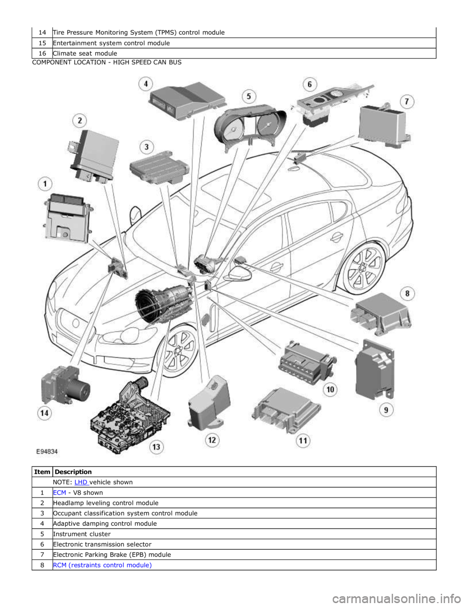
Tire Pressure Monitoring System (TPMS) control module 15 Entertainment system control module 16 Climate seat module COMPONENT LOCATION - HIGH SPEED CAN BUS
Item Description NOTE: LHD vehicle shown 1 ECM - V8 shown 2 Headlamp leveling control module 3 Occupant classification system control module 4 Adaptive damping control module 5 Instrument cluster 6 Electronic transmission selector 7 Electronic Parking Brake (EPB) module 8 RCM (restraints control module)
Page 2170 of 3039

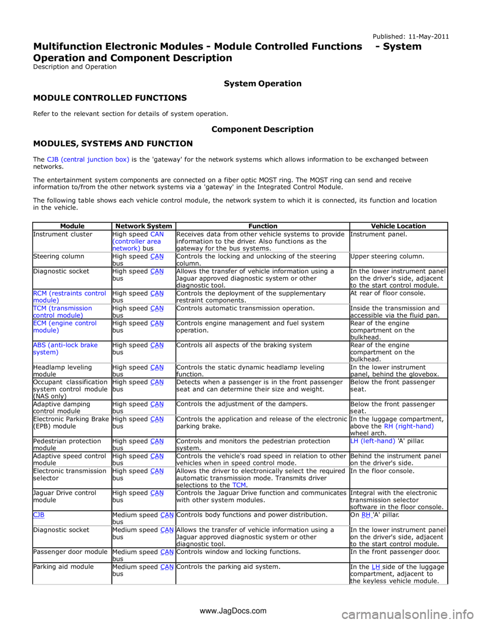
Instrument cluster
High speed CAN
(controller area network) bus Receives data from other vehicle systems to provide
information to the driver. Also functions as the gateway for the bus systems. Instrument panel. Steering column
High speed CAN bus Controls the locking and unlocking of the steering
column. Upper steering column. Diagnostic socket
High speed CAN bus Allows the transfer of vehicle information using a
Jaguar approved diagnostic system or other diagnostic tool. In the lower instrument panel
on the driver's side, adjacent
to the start control module. RCM (restraints control module) High speed CAN bus Controls the deployment of the supplementary
restraint components. At rear of floor console. TCM (transmission
control module) High speed CAN bus Controls automatic transmission operation.
Inside the transmission and
accessible via the fluid pan. ECM (engine control
module) High speed CAN bus Controls engine management and fuel system
operation. Rear of the engine
compartment on the
bulkhead. ABS (anti-lock brake
system) High speed CAN bus Controls all aspects of the braking system
Rear of the engine
compartment on the
bulkhead. Headlamp leveling
module High speed CAN bus Controls the static dynamic headlamp leveling
function. In the lower instrument panel, behind the glovebox. Occupant classification
system control module (NAS only) High speed CAN bus Detects when a passenger is in the front passenger
seat and can determine their size and weight. Below the front passenger
seat. Adaptive damping
control module High speed CAN bus Controls the adjustment of the dampers.
Below the front passenger
seat. Electronic Parking Brake
(EPB) module High speed CAN bus Controls the application and release of the electronic
parking brake. In the luggage compartment,
above the RH (right-hand)
wheel arch. Pedestrian protection
module High speed CAN bus Controls and monitors the pedestrian protection system. LH (left-hand) 'A' pillar. Adaptive speed control
module High speed CAN bus Controls the vehicle's road speed in relation to other
vehicles when in speed control mode. Behind the instrument panel
on the driver's side. Electronic transmission
selector High speed CAN bus Allows the driver to electronically select the required
automatic transmission mode. Transmits driver
selections to the TCM. In the floor console. Jaguar Drive control
module High speed CAN bus Controls the Jaguar Drive function and communicates
with other system modules. Integral with the electronic
transmission selector
software in the floor console. CJB
Medium speed CAN bus Controls body functions and power distribution. On RH 'A' pillar. Diagnostic socket
Medium speed CAN bus Allows the transfer of vehicle information using a
Jaguar approved diagnostic system or other diagnostic tool. In the lower instrument panel
on the driver's side, adjacent
to the start control module. Passenger door module
Medium speed CAN bus Controls window and locking functions. In the front passenger door. Parking aid module
Medium speed CAN bus Controls the parking aid system.
In the LH side of the luggage compartment, adjacent to
the keyless vehicle module. www.JagDocs.com
Page 2724 of 3039

Cooper Pegler
Burgess Hill
Sussex
RH 15 9LA
Telephone (014446) 42526
Sika Ltd
Watchmead
Welwyn Garden City
Hertfordshire
AL7 1BQ
Telephone (01707) 394444
www.sika.co.uk
SATA Spray Equipment
Minden Industrial equipment
16 Greyfriars Road
Moreton Hall
Bury St Edmunds
Suffolk
IP32 7DX
Telephone (01284) 760791
www.sata.com
Henkel Loctite Adhesives Limited
Technologies House
Wood Lane End
Hemel Hempstead
Hertfordshire
HP2 4RQ
Telephone (01442) 278000
www.loctite.co.uk
Teroson
Henkel Ltd
Apollo Court
2 Bishops Square Business Park
Hatfield
Hertfordshire
AL10 9EY
Telephone (01707) 635000
www.henkel.co.uk
Underbody sealer
Under floor areas and the front part of the spare wheel well are treated with a plastisol PVC underbody sealer. This material is
not suitable for re-treatment. When repairing areas of underbody sealer, strip the factory-applied underbody sealer back to a
suitable break point. Ensure that a clean metal surface is exposed and that the edge of the existing adheres soundly to the
panel.
Apply new underbody sealer between primer and surface paint operations. Apply seam sealer as necessary before application
of underbody sealer. Ensure that blanking plugs and grommets in the floor pan (except those used for wax injection) are fitted
before underbody sealer application. Refit any heat-fusible plugs which have been disturbed in repair with the aid of a hot air
blower, or replace with rubber grommets
CAUTION: Ensure that suspension units, wheels, tires, power unit, drive shafts, exhaust and brakes, (including all
mounting points), are shielded prior to application of fresh underbody sealer. www.JagDocs.com