2010 JAGUAR XFR automatic transmission
[x] Cancel search: automatic transmissionPage 1411 of 3039
Published: 11-May-2011
Automatic Transmission/Transaxle - TDV6 3.0L Diesel /V8 5.0L Petrol/V8 S/C 5.0L Petrol - Transmission Description - System Operation and Component Description
Description and Operation
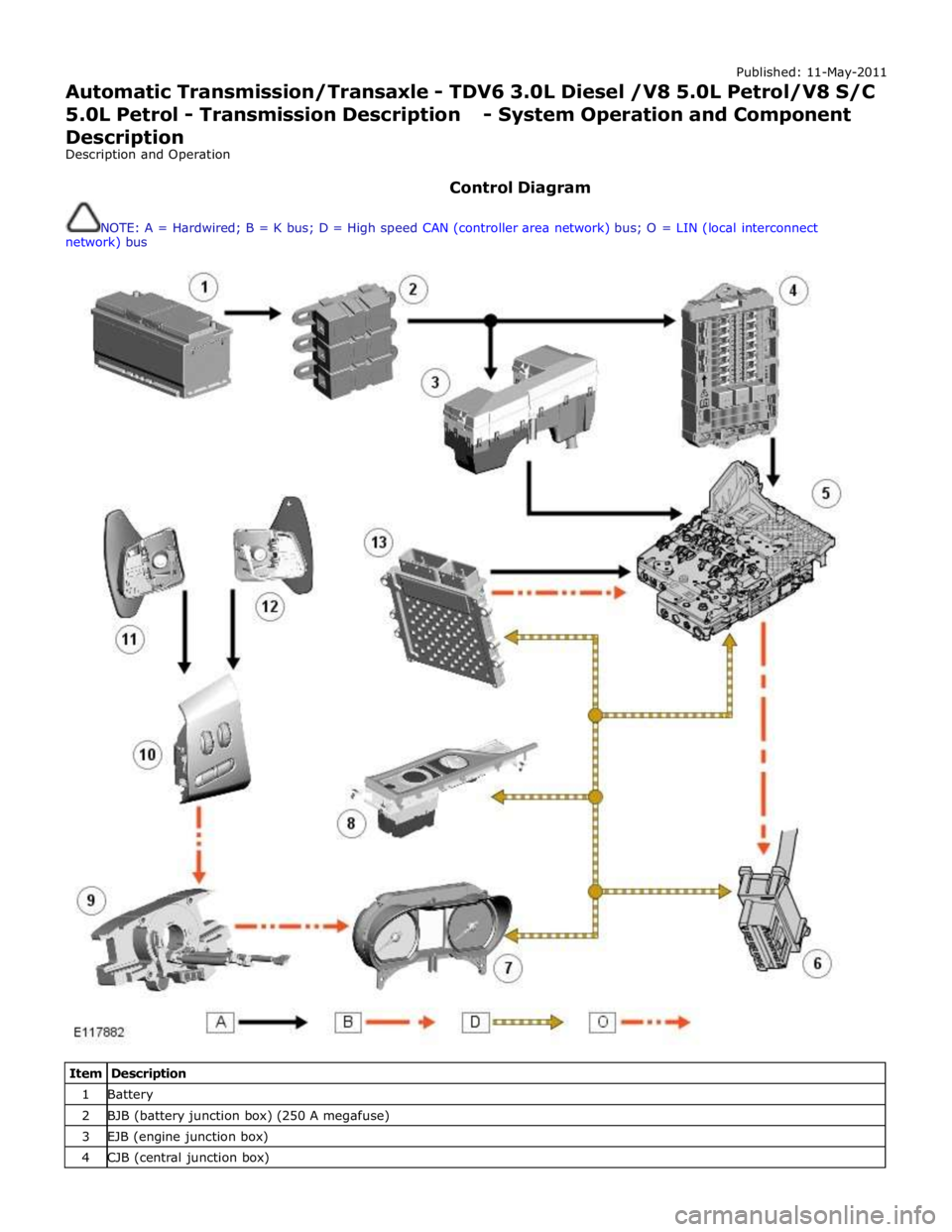
Control Diagram
NOTE: A = Hardwired; B = K bus; D = High speed CAN (controller area network) bus; O = LIN (local interconnect
network) bus
Item Description 1 Battery 2 BJB (battery junction box) (250 A megafuse) 3 EJB (engine junction box) 4 CJB (central junction box)
Page 1422 of 3039
1 Transmission selected gear status 2 MIL (malfunction indicator lamp) 3 Message center The instrument cluster is connected to the TCM via the high speed CAN bus. Transmission status is transmitted by the TCM and displayed to the driver in one of two displays in the instrument cluster. For additional information, refer to 413-01
Instrument Cluster.
Malfunction Indicator Lamp
The MIL (malfunction indicator lamp) is located in the tachometer in the instrument cluster. Transmission related faults which
may affect the vehicle emissions output will illuminate the MIL.
The MIL is illuminated by the ECM (engine control module) on receipt of a relevant fault message from the TCM on the high speed CAN. The nature of the fault can be diagnosed using a Jaguar approved diagnostic system which reads the fault codes stored in the TCM memory.
Transmission Status Display
The transmission status display is located in a LCD (liquid crystal display) at the top of the instrument cluster, between the
speedometer and the tachometer. The LCD shows the JaguarDrive selector position or the selected gear when in manual 'Jaguar Sequential Shift' mode.
The following table shows the displays and their descriptions.
Symbol Description P Park selected R Reverse selected N Neutral selected D Drive selected S Sport mode selected 1 1st gear selected (manual Jaguar sequential shift mode) 2 2nd gear selected (manual Jaguar sequential shift mode) 3 3rd gear selected (manual Jaguar sequential shift mode) 4 4th gear selected (manual Jaguar sequential shift mode) 5 5th gear selected (manual Jaguar sequential shift mode) 6 6th gear selected (manual Jaguar sequential shift mode) The message center is located in the lower center of the instrument cluster. The message center is a LCD to relay vehicle status and operating information to the driver and can display messages relating to a number of the vehicle systems. If a
transmission fault occurs, the message center will display the message 'GEARBOX FAULT'.
TRANSMISSION CONTROL MODULE
The TCM outputs signals to control the shift control solenoid valve and the EPRS (electronic pressure regulating solenoid) to control the hydraulic operation of the transmission.
The TCM processes signals from the transmission speed and temperature sensors, the ECM and other vehicle systems. From the received signal inputs and pre-programmed data, the module calculates the correct gear, torque converter clutch setting
and optimum pressure settings for gear shift and lock-up clutch control.
The ECM supplies the engine management data over the high speed CAN bus. The TCM requires engine data to efficiently control the transmission operation, for example; flywheel torque, engine speed, accelerator pedal angle, engine temperature.
The steering angle sensor and the ABS (anti-lock brake system) module also supply data to the TCM on the high speed CAN bus. The TCM uses data from these systems to suspend gear changes when the vehicle is cornering and/or the ABS module is controlling braking or traction control.
Using the signal inputs and the memorized data, the TCM control program computes the correct gear and torque converter lock-up clutch setting and the optimum pressure settings for gear shift and lock-up clutch control. Special output-side modules
(power output stages, current regulator circuits), allow the TCM to control the solenoid valves and pressure regulators and consequently precisely control the hydraulics of the automatic transmission. In addition, the amount and duration of engine
interventions are supplied to the engine management by way of the CAN bus.
The transmission has a fully electronic JaguarDrive selector with no Bowden cable connection to the transmission. The
transmission selections are made using a rotary JaguarDrive selector which rises from the floor console once the engine is
running. Rotation of the JaguarDrive selector to any of the five positions is sensed by the TCM via the high speed CAN bus. The TCM then reacts according to the selected position. The 'S' (sport) position selection allows the TCM to operate the transmission using the semi-automatic 'Jaguar Sequential Shift'.
Gear selections are sensed by the TCM when the driver operates the steering wheel paddle switches. Once the JaguarDrive selector position is confirmed, the TCM outputs appropriate information on the high speed CAN bus.
If the JaguarDrive selector is in 'D', 'Jaguar Sequential Shift' is temporary and will cancel after a time period or can be cancelled
by pressing and holding the + paddle for approximately 2 seconds.
If the JaguarDrive selector is in 'S', 'Jaguar Sequential Shift' is permanent and can only be cancelled by pressing and holding
the + paddle for approximately 2 seconds or by moving the JaguarDrive selector to the 'D' position.
www.JagDocs.com
Page 1423 of 3039

The TCM can be reprogrammed using a Jaguar approved diagnostic system using a flash code. The TCM processor has a 440 kb internal flash memory. Of this capacity, approximately 370 kb are used by the basic transmission program. The remainder,
approximately 70 kb is used to store vehicle-specific application data.
Engine Stall
If the vehicle stalls it will coast down in gear, with the transmission providing drive to the engine. A restart can be attempted
at this point and the engine may start and the driver can continue.
If the coast down speed reduces such that the speed of the engine is less than 600 rev/min, the transmission will go to
neutral, D illumination will flash in the instrument cluster. The driver needs to select neutral or park and then press the brake
pedal to restart the engine.
If the start/stop button is pressed when driving, the message ENGINE STOP BUTTON PRESSED is displayed in the message
center but there will be no change to the ignition state. If the driver requires to switch off the engine, the start/stop button
must be pressed for a second time. The engine will be stopped and will be back driven by the transmission as the vehicle
coasts down. When the engine speed is less than 600 rev/min the transmission engages neutral (flashing D illumination in the
instrument cluster). When vehicle speed is less than 2 km/h (1.2 mph) Park is engaged. The JaguarDrive selector automatically
rotates back to its lowered P position and the vehicle ignition is switched off.
The park engagement is prevented in a stall case as the ignition power is on and D was the last selected gear. The park
engagement speed at ignition off is from the least value of the wheel speeds (CAN signal) and transmission output speed (internal signal).
TRANSMISSION Component Description
The transmission comprises the main casing which houses all of the transmission components. The main casing also
incorporates an integral bell housing.
A fluid pan is attached to the lower face of the main casing and is secured with bolts. The fluid pan is sealed to the main
casing with a gasket. Removal of the fluid pan allows access to the Mechatronic valve block. The fluid pan has a magnet
located around the drain plug which collects any metallic particles present in the transmission fluid.
A fluid filter is located inside the fluid pan. If the transmission fluid becomes contaminated or after any service work, the fluid
pan with integral filter must be replaced.
The integral bell housing provides protection for the torque converter assembly and also provides the attachment for the
gearbox to the engine cylinder block. The torque converter is a non-serviceable assembly which also contains the lock-up clutch
mechanism. The torque converter drives a crescent type pump via drive tangs. The fluid pump is located in the main casing,
behind the torque converter.
The main casing contains the following major components:
Input shaft
Output shaft
Mechatronic valve block which contains the solenoids, speed sensors and the TCM Three rotating multiplate drive clutches
Two fixed multiplate brake clutches
A single planetary gear train and a double planetary gear train.
Page 1434 of 3039
solenoid valve in the valve housing directs hydraulic pressure to the lock cylinder, which moves the piston within the cylinder
and releases the park lock pawl at the rear of the transmission by means of a connecting rod. The solenoid on the lock cylinder
is energized and locks the cylinder piston in the unlocked position. Additional locking of the piston is achieved with ball
catches within the lock cylinder.
When park is selected, the solenoid on the lock cylinder is de-energized, the ball catches are released and the piston is free to
move in the lock cylinder. The solenoid in the valve housing is also de-energized. The spring loaded parking disc pulls the
cylinder piston in the park direction which allows the park disc to move on its mounting. This movement is transferred via the
connecting rod to parking pawl, which is engaged in the park lock gear.
If an electrical failure occurs, the park lock can be manually released by means of an emergency park release lever located in
the floor console. The lever is connected to the parking disc by a cable and allows the park lock to be released manually. For
additional information, refer to 307-05B Automatic Transmission/Transaxle External Controls.
TRANSMISSION CONTROL MODULE
The TCM is an integral part of the Mechatronic valve block which is located at the bottom of the transmission, within the fluid pan. The TCM is the main controlling component of the transmission.
The TCM processes signals from the transmission speed and temperature sensors, ECM and other vehicle systems. From the received signal inputs and pre-programmed data, the module calculates the correct gear, torque converter clutch setting and
optimum pressure settings for gear shift and lock-up clutch control.
Page 1435 of 3039
Published: 25-Aug-2011
Automatic Transmission/Transaxle - TDV6 3.0L Diesel /V8 5.0L Petrol/V8 S/C 5.0L Petrol - Diagnostics
Diagnosis and Testing
Principle of Operation
For a detailed description of the automatic transmission/transaxle, refer to the relevant Description and Operation section n
the workshop manual. REFER to: (307-01B Automatic Transmission/Transaxle - TDV6 3.0L Diesel /V8 5.0L Petrol/V8 S/C 5.0L
Petrol)
Transmission Description (Description and Operation), Transmission Description (Description and Operation), Transmission Description (Description and Operation).
Fluid Level and Condition Check
CAUTION: The vehicle should not be driven if the fluid level is low as internal failure can result.
NOTE: The transmission fluid temperature must not be allowed to exceed 50°C (122°F) whilst checking level. Should the
temperature rise above this figure, abort the check and allow the transmission fluid to cool to below 30°C (86°F).
This vehicle is not equipped with a fluid level indicator. An incorrect level may affect the transmission operation and could
result in transmission damage. To correctly check and add fluid to the transmission.
REFER to: Transmission Fluid Level Check (307-01B Automatic Transmission/Transaxle - TDV6 3.0L Diesel /V8 5.0L Petrol/V8 S/C 5.0L Petrol, General Procedures).
High Fluid Level
A fluid level that is too high may cause the fluid to become aerated due to the churning action of the rotating internal parts.
This will cause erratic control pressure, foaming, loss of fluid from the vent tube and possible transmission damage. If an
overfill condition is identified, with the engine at idle ensure the fluid temperature is within the specified range and allow the
excess fluid to drain until a small thread of fluid runs from the filler/level plug hole.
Low Fluid Level
A low fluid level could result in poor transmission engagement, slipping, or damage. This could also indicate a leak in one of
the transmission seals or gaskets.
REFER to: Transmission Fluid Level Check (307-01B Automatic Transmission/Transaxle - TDV6 3.0L Diesel /V8 5.0L Petrol/V8 S/C 5.0L Petrol, General Procedures).
Adding Fluid
CAUTION: The use of any other type of transmission fluid other than that specified can result in transmission damage.
If fluid needs to be added, add fluid in 0.50 liter increments through the fill hole Opening. Do not overfill the fluid. For fluid
type, refer to the General Specification chart in this section.
REFER to: Specifications (307-01B Automatic Transmission/Transaxle - TDV6 3.0L Diesel /V8 5.0L Petrol/V8 S/C 5.0L Petrol, Specifications).
Fluid Condition Check
1. Check the fluid level.
REFER to: Transmission Fluid Level Check (307-01B Automatic Transmission/Transaxle - TDV6 3.0L Diesel /V8 5.0L Petrol/V8 S/C 5.0L Petrol, General Procedures).
2. Observe the color and the odor of the fluid. The color under normal circumstances should be Honey.
3. Allow the fluid to drip onto a facial tissue and examine the stain.
4. If evidence of solid material is found, the transmission fluid pan should be removed for further inspection.
NOTE: In the event of a transmission unit replacement for internal failure, the oil cooler and pipes must also be replaced.
Inspection and Verification
1. Verify the customer concern.
2. Visually inspect for obvious signs of damage and system integrity.
Page 1436 of 3039
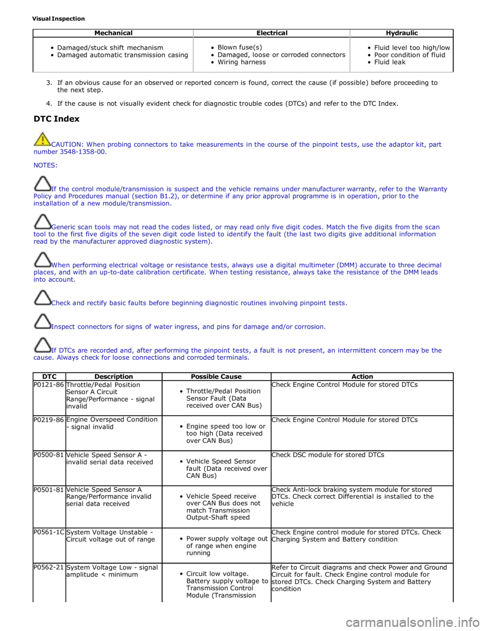
Visual Inspection
Mechanical Electrical Hydraulic
Damaged/stuck shift mechanism
Damaged automatic transmission casing
Blown fuse(s)
Damaged, loose or corroded connectors
Wiring harness
Fluid level too high/low
Poor condition of fluid
Fluid leak
3. If an obvious cause for an observed or reported concern is found, correct the cause (if possible) before proceeding to
the next step.
4. If the cause is not visually evident check for diagnostic trouble codes (DTCs) and refer to the DTC Index.
DTC Index
CAUTION: When probing connectors to take measurements in the course of the pinpoint tests, use the adaptor kit, part
number 3548-1358-00.
NOTES:
If the control module/transmission is suspect and the vehicle remains under manufacturer warranty, refer to the Warranty
Policy and Procedures manual (section B1.2), or determine if any prior approval programme is in operation, prior to the
installation of a new module/transmission.
Generic scan tools may not read the codes listed, or may read only five digit codes. Match the five digits from the scan
tool to the first five digits of the seven digit code listed to identify the fault (the last two digits give additional information
read by the manufacturer approved diagnostic system).
When performing electrical voltage or resistance tests, always use a digital multimeter (DMM) accurate to three decimal
places, and with an up-to-date calibration certificate. When testing resistance, always take the resistance of the DMM leads
into account.
Check and rectify basic faults before beginning diagnostic routines involving pinpoint tests.
Inspect connectors for signs of water ingress, and pins for damage and/or corrosion.
If DTCs are recorded and, after performing the pinpoint tests, a fault is not present, an intermittent concern may be the
cause. Always check for loose connections and corroded terminals.
DTC Description Possible Cause Action P0121-86 Throttle/Pedal Position
Sensor A Circuit
Range/Performance - signal
invalid
Throttle/Pedal Position
Sensor Fault (Data
received over CAN Bus) Check Engine Control Module for stored DTCs P0219-86 Engine Overspeed Condition
- signal invalid
Engine speed too low or
too high (Data received
over CAN Bus) Check Engine Control Module for stored DTCs P0500-81
Vehicle Speed Sensor A -
invalid serial data received
Vehicle Speed Sensor
fault (Data received over
CAN Bus) Check DSC module for stored DTCs P0501-81 Vehicle Speed Sensor A
Vehicle Speed receive Check Anti-lock braking system module for stored Range/Performance invalid DTCs. Check correct Differential is installed to the serial data received over CAN Bus does not
vehicle match Transmission Output-Shaft speed P0561-1C
System Voltage Unstable -
Circuit voltage out of range
Power supply voltage out
of range when engine
running Check Engine control module for stored DTCs. Check
Charging System and Battery condition P0562-21
System Voltage Low - signal
amplitude < minimum
Circuit low voltage.
Battery supply voltage to
Transmission Control
Module (Transmission Refer to Circuit diagrams and check Power and Ground
Circuit for fault. Check Engine control module for
stored DTCs. Check Charging System and Battery
condition
Page 1449 of 3039
Published: 11-May-2011
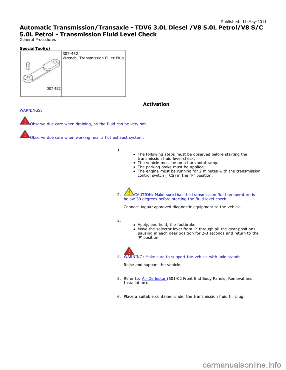
Automatic Transmission/Transaxle - TDV6 3.0L Diesel /V8 5.0L Petrol/V8 S/C 5.0L Petrol - Transmission Fluid Level Check
General Procedures
WARNINGS: Activation
Observe due care when draining, as the fluid can be very hot.
Observe due care when working near a hot exhaust system.
1.
The following steps must be observed before starting the
transmission fluid level check.
The vehicle must be on a horizontal ramp.
The parking brake must be applied.
The engine must be running for 2 minutes with the transmission
control switch (TCS) in the "P" position.
2. CAUTION: Make sure that the transmission fluid temperature is
below 30 degrees before starting the fluid level check.
Connect Jaguar approved diagnostic equipment to the vehicle.
3.
Apply, and hold, the footbrake.
Move the selector lever from 'P' through all the gear positions,
pausing in each gear position for 2-3 seconds and return to the
'P' position.
4. WARNING: Make sure to support the vehicle with axle stands.
Raise and support the vehicle.
5. Refer to: Air Deflector (501-02 Front End Body Panels, Removal and Installation).
6. Place a suitable container under the transmission fluid fill plug. 307-452
Wrench, Transmission Filler Plug Special Tool(s)
Page 1453 of 3039
Published: 11-May-2011
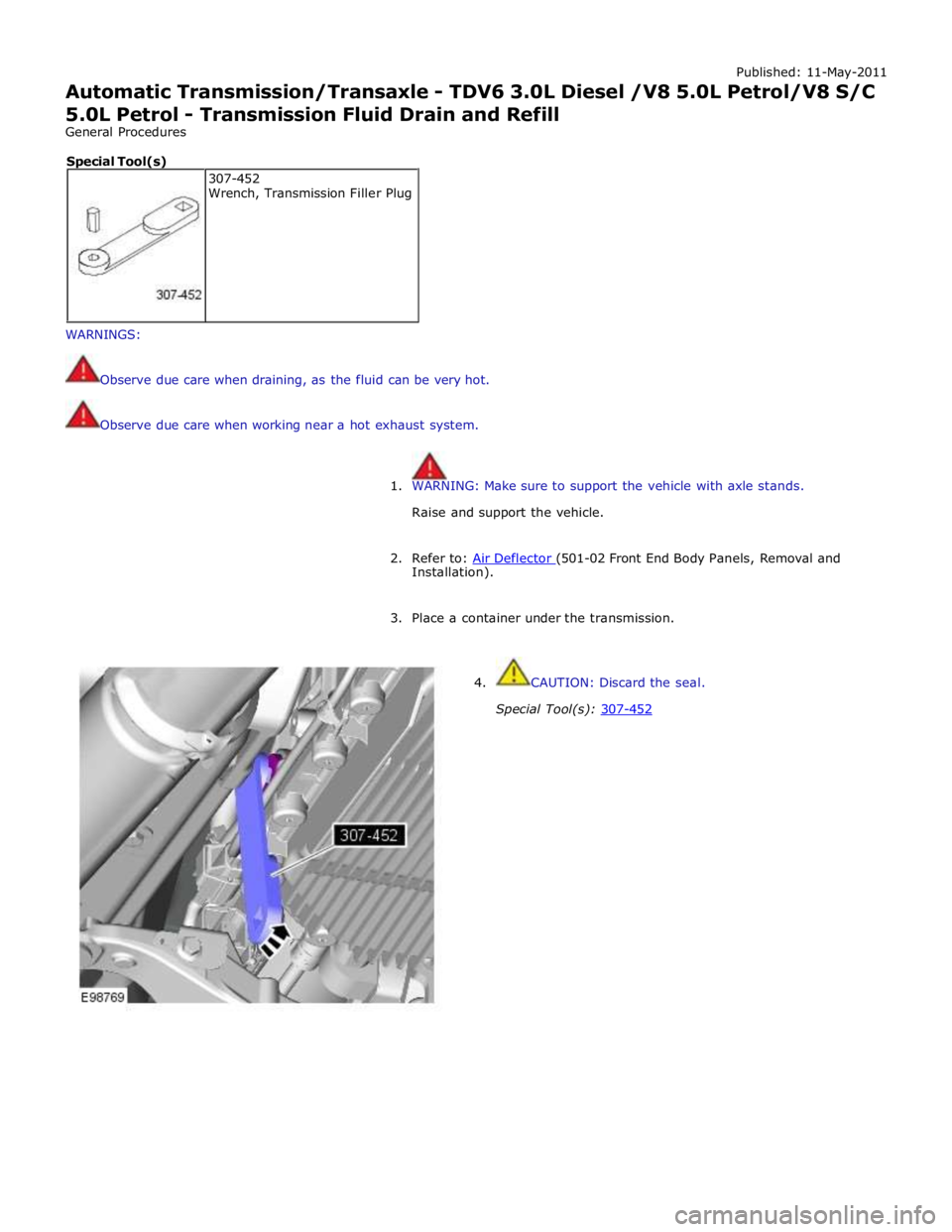
Automatic Transmission/Transaxle - TDV6 3.0L Diesel /V8 5.0L Petrol/V8 S/C 5.0L Petrol - Transmission Fluid Drain and Refill
General Procedures
WARNINGS:
Observe due care when draining, as the fluid can be very hot.
Observe due care when working near a hot exhaust system.
1. WARNING: Make sure to support the vehicle with axle stands.
Raise and support the vehicle.
2. Refer to: Air Deflector (501-02 Front End Body Panels, Removal and Installation).
3. Place a container under the transmission.
4. CAUTION: Discard the seal.
Special Tool(s): 307-452 307-452
Wrench, Transmission Filler Plug Special Tool(s)