2010 JAGUAR XFR automatic transmission
[x] Cancel search: automatic transmissionPage 2171 of 3039
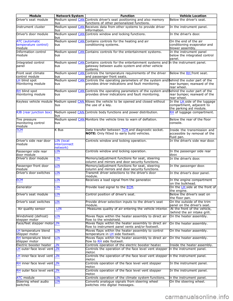
Module Network System Function Vehicle Location
Driver's seat module Medium speed CAN Controls driver's seat positioning and also memory Below the driver's seat. bus functions of other personalized functions.
Instrument cluster Medium speed CAN Receives data from other systems to provide driver In the instrument panel. bus information.
Driver's door module Medium speed CAN Controls window and locking functions. In the driver's door. bus
ATC (automatic Medium speed CAN Contains controls for the heating and air On the end of the air
temperature control)
module bus conditioning systems.
conditioning evaporator and
blower assembly.
Information control Medium speed CAN Contains controls for the entertainment systems. In the instrument panel module bus
below the integrated control
panel.
Integrated control Medium speed CAN Contains controls for the entertainment systems and In the instrument panel. panel bus
gateway between audio system and other vehicle
systems.
Front seat climate Medium speed CAN Controls the temperature requirements of the driver Below the RH front seat. control module bus and passenger front seats.
LH blind spot Medium speed CAN Controls the operating parameters of the system and Behind the outer part of the monitoring module bus provides driver indications and fault monitoring.
rear bumper, rearward of the
rear wheel.
RH blind spot Medium speed CAN Controls the operating parameters of the system and Behind the outer part of the monitoring module bus provides driver indications and fault monitoring.
rear bumper, rearward of the
rear wheel.
Keyless vehicle module Medium speed CAN Allows the vehicle to be opened and closed without In the LH side of the luggage bus the use of a key.
compartment, adjacent to
the parking aid module.
RJB (rear junction box) Medium speed CAN Controls body functions and power distribution. RH of luggage compartment. bus
Tire pressure Medium speed CAN Monitors the vehicle tires to warn of deflation. Below the rear of the floor monitoring control
module bus console.
TCM K Bus Data transfer between TCM and diagnostic socket. NOTE: Only fitted to early build vehicles. Inside the transmission and
accessible by removal of the
fluid pan.
Driver's side rear door
module LIN (local
interconnect
network) Controls window and locking operation. In the driver's side rear door.
Passenger side rear
door module LIN Controls window and locking operation. In the passenger side rear
door.
Driver's door module LIN Memory/adjustment functions for seat, steering
column and mirrors and door security functions. In the driver's door.
Passenger front door
module LIN Memory/adjustment functions for seat, steering
column and mirrors and door security functions. In the passenger door.
Driver's door switches LIN Transmit driver selections to the driver's door
module. In the driver's door panel.
ECM LIN Receives a load signal from the generator. In the engine compartment
on the bulkhead.
Generator LIN Provide load signal to the ECM. On the LH side at the front of the engine.
Driver's seat module LIN Control position of driver's seat. Below the driver's seat on
the floor pan.
Driver's seat switches LIN Provide driver selection inputs to the driver's seat
module. On the outside of the trim
panel on the driver's seat.
Air quality sensor LIN Measures quality of air entering the vehicle interior. At the front of the vehicle,
behind the air intake grill.
Windshield (defrost)
stepper motor LIN Moves flaps within the heater assembly to direct air
flow to the windshield. On the heater assembly.
Face/feet stepper motor LIN Moves flaps within the heater assembly to direct air
flow to instrument panel vents and/or footwell. On the heater assembly.
LH temperature blend
stepper motor
RH temperature blend
stepper motor LIN Moves flaps within the heater assembly to control
temperature in LH side footwell.
LIN Moves flaps within the heater assembly to direct air
flow to RH side footwell. On the heater assembly.
On the heater assembly.
Electric booster heater LIN Controls operation of the electric booster heater. Inside the heater assembly.
LH outer face level vent LIN Controls the operation of the face level vent stepper In the instrument panel.
motor.
LH inner face level vent LIN Controls the operation of the face level vent stepper In the instrument panel.
motor.
RH inner face level vent LIN Controls operation of the face level vent stepper
motor.
RH outer face level vent LIN Controls operation of the face level vent stepper
motor. In the instrument panel.
In the instrument panel.
ATC module LIN Controls operation of the climate system functions. In the instrument panel.
Steering wheel audio
switches LIN Converts analogue signals from steering wheel
switches into digital messages. On the steering wheel.
Page 2172 of 3039
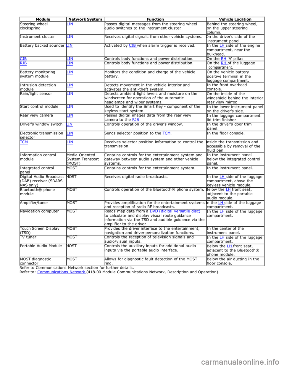
Module Network System Function Vehicle Location
Steering wheel
clockspring LIN Passes digital messages from the steering wheel
audio switches to the instrument cluster. Behind the steering wheel,
on the upper steering
column.
Instrument cluster LIN Receives digital signals from other vehicle systems. On the driver's side of the
instrument panel.
Battery backed sounder LIN Activated by CJB when alarm trigger is received. In the LH side of the engine compartment, near the
bulkhead.
CJB LIN Controls body functions and power distribution. On the RH 'A' pillar.
RJB LIN Controls body functions and power distribution. On the RH of the luggage compartment.
Battery monitoring
system module
Intrusion detection
module LIN Monitors the condition and charge of the vehicle
battery.
LIN Detects movement in the vehicle interior and
activates the anti-theft system. On the vehicle battery
positive terminal in the
luggage compartment.
In the front overhead
console.
Rain/light sensor LIN Detects ambient light levels and moisture on the
windscreen for operation of the automatic
headlamps and wiper systems.
Start control module LIN Used to identify the Smart Key - component of the
keyless start system.
Rear view camera LIN Passes digital images data from the rear view
camera to the RJB On the inside of the
windshield behind the interior
rear view mirror.
In the lower instrument panel
on the driver's side.
In the luggage compartment
lid trim finisher.
Driver's window switch LIN Controls operation of the driver's window. In the driver's door trim
panel.
Electronic transmission
selector LIN Sends selector position to the TCM. In the floor console. TCM LIN Receives selector position information to control the Inside the transmission and
Information control
module
Media Oriented
System Transport
(MOST) transmission.
Contains controls for the entertainment system and
gateway between audio system and other vehicle
systems. accessible by removal of the
fluid pan.
In the instrument panel
below the integrated control
panel.
Integrated control
panel MOST Contains controls for the entertainment system. In the instrument panel.
Digital Audio Broadcast MOST Receives digital radio broadcasts. In the LH side of the luggage (DAB) receiver (SDARS
NAS only)
Bluetooth® phone
module compartment, above the
keyless vehicle module.
MOST Controls operation of the Bluetooth® phone system. Below the LH front seat, adjacent to the portable
audio module.
Amplifier/tuner MOST Provides amplification for the entertainment systems In the LH side of the luggage and reception of radio RF broadcasts.
Navigation computer MOST Reads map data from a DVD (digital versatile disc)
to calculate and display visual route guidance
information via the TSD and audible guidance via the
amplifier to the driver. compartment.
In the LH side of the luggage compartment.
Touch Screen Display
(TSD) MOST Provides the driver interface to the entertainment,
navigation and driver personalization functions. In the center of the
instrument panel.
TV tuner MOST Controls the reception of television signals and
audio/visual inputs.
Portable Audio Module MOST Controls the auxiliary inputs for additional audio
inputs via the portable audio interface. In the LH side of the luggage compartment.
Below the LH front seat, adjacent to the Bluetooth®
phone module.
MOST diagnostic
connector MOST Allows for diagnostic fault detection of the MOST
ring. Below the air ducting in the
floor console.
Refer to Communications Network section for further details.
Refer to: Communications Network (418-00 Module Communications Network, Description and Operation).
Page 2294 of 3039
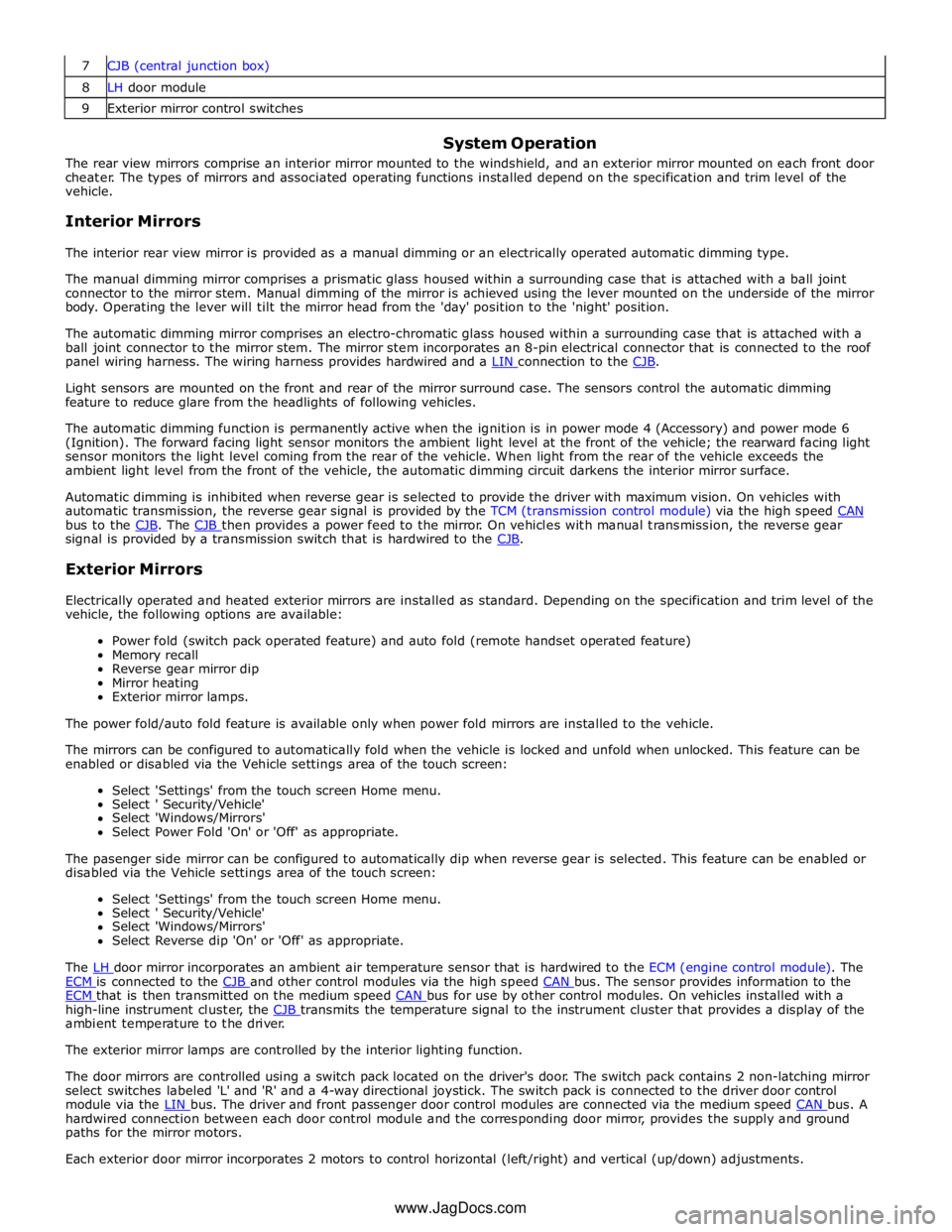
8 LH door module 9 Exterior mirror control switches
System Operation
The rear view mirrors comprise an interior mirror mounted to the windshield, and an exterior mirror mounted on each front door
cheater. The types of mirrors and associated operating functions installed depend on the specification and trim level of the
vehicle.
Interior Mirrors
The interior rear view mirror is provided as a manual dimming or an electrically operated automatic dimming type.
The manual dimming mirror comprises a prismatic glass housed within a surrounding case that is attached with a ball joint
connector to the mirror stem. Manual dimming of the mirror is achieved using the lever mounted on the underside of the mirror
body. Operating the lever will tilt the mirror head from the 'day' position to the 'night' position.
The automatic dimming mirror comprises an electro-chromatic glass housed within a surrounding case that is attached with a
ball joint connector to the mirror stem. The mirror stem incorporates an 8-pin electrical connector that is connected to the roof
panel wiring harness. The wiring harness provides hardwired and a LIN connection to the CJB.
Light sensors are mounted on the front and rear of the mirror surround case. The sensors control the automatic dimming
feature to reduce glare from the headlights of following vehicles.
The automatic dimming function is permanently active when the ignition is in power mode 4 (Accessory) and power mode 6
(Ignition). The forward facing light sensor monitors the ambient light level at the front of the vehicle; the rearward facing light
sensor monitors the light level coming from the rear of the vehicle. When light from the rear of the vehicle exceeds the
ambient light level from the front of the vehicle, the automatic dimming circuit darkens the interior mirror surface.
Automatic dimming is inhibited when reverse gear is selected to provide the driver with maximum vision. On vehicles with
automatic transmission, the reverse gear signal is provided by the TCM (transmission control module) via the high speed CAN bus to the CJB. The CJB then provides a power feed to the mirror. On vehicles with manual transmission, the reverse gear signal is provided by a transmission switch that is hardwired to the CJB.
Exterior Mirrors
Electrically operated and heated exterior mirrors are installed as standard. Depending on the specification and trim level of the
vehicle, the following options are available:
Power fold (switch pack operated feature) and auto fold (remote handset operated feature)
Memory recall
Reverse gear mirror dip
Mirror heating
Exterior mirror lamps.
The power fold/auto fold feature is available only when power fold mirrors are installed to the vehicle.
The mirrors can be configured to automatically fold when the vehicle is locked and unfold when unlocked. This feature can be
enabled or disabled via the Vehicle settings area of the touch screen:
Select 'Settings' from the touch screen Home menu.
Select ' Security/Vehicle'
Select 'Windows/Mirrors'
Select Power Fold 'On' or 'Off' as appropriate.
The pasenger side mirror can be configured to automatically dip when reverse gear is selected. This feature can be enabled or
disabled via the Vehicle settings area of the touch screen:
Select 'Settings' from the touch screen Home menu.
Select ' Security/Vehicle'
Select 'Windows/Mirrors'
Select Reverse dip 'On' or 'Off' as appropriate.
The LH door mirror incorporates an ambient air temperature sensor that is hardwired to the ECM (engine control module). The ECM is connected to the CJB and other control modules via the high speed CAN bus. The sensor provides information to the ECM that is then transmitted on the medium speed CAN bus for use by other control modules. On vehicles installed with a high-line instrument cluster, the CJB transmits the temperature signal to the instrument cluster that provides a display of the ambient temperature to the driver.
The exterior mirror lamps are controlled by the interior lighting function.
The door mirrors are controlled using a switch pack located on the driver's door. The switch pack contains 2 non-latching mirror
select switches labeled 'L' and 'R' and a 4-way directional joystick. The switch pack is connected to the driver door control
module via the LIN bus. The driver and front passenger door control modules are connected via the medium speed CAN bus. A hardwired connection between each door control module and the corresponding door mirror, provides the supply and ground
paths for the mirror motors.
Each exterior door mirror incorporates 2 motors to control horizontal (left/right) and vertical (up/down) adjustments. www.JagDocs.com
Page 2459 of 3039
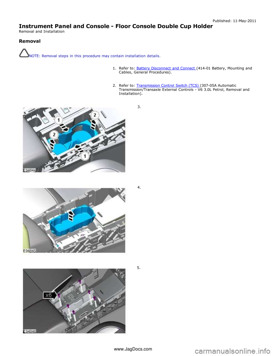
Published: 11-May-2011
Instrument Panel and Console - Floor Console Double Cup Holder
Removal and Installation
Removal
NOTE: Removal steps in this procedure may contain installation details.
1. Refer to: Battery Disconnect and Connect (414-01 Battery, Mounting and Cables, General Procedures).
2. Refer to: Transmission Control Switch (TCS) (307-05A Automatic Transmission/Transaxle External Controls - V6 3.0L Petrol, Removal and
Installation).
3.
4.
5. www.JagDocs.com
Page 2784 of 3039
Front End Sheet Metal Repairs - Front Side Member
Removal and Installation
Removal Published: 11-May-2011
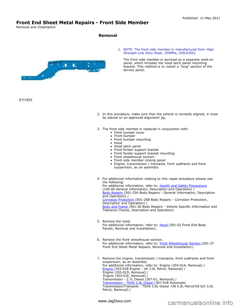
1. NOTE: The front side member is manufactured from High
Strength Low Alloy Steel, 350MPa, (HSLA350).
The front side member is serviced as a separate weld-on
panel, which includes the hood latch panel mounting
bracket. This method is to install a "long" section of the
service panel.
2. In this procedure, make sure that the vehicle is correctly aligned, it must
be placed on an approved alignment jig.
3. The front side member is replaced in conjunction with:
Front bumper cover
Front bumper
Front bumper mounting
Hood
Hood latch panel
Front fender support bracket
Front fender support bracket mounting
Front wheelhouse section
Front side member closing panel
Engine, transmission / transaxle, front subframe and front
suspension, as an assembly
4. For additional information relating to this repair procedure please see
the following:
For additional information, refer to: Health and Safety Precautions (100-00 General Information, Description and Operation) /
Body Repairs (501-25A Body Repairs - General Information, Description and Operation) /
Corrosion Protection (501-25B Body Repairs - Corrosion Protection, Description and Operation) /
Body and Frame (501-26 Body Repairs - Vehicle Specific Information and Tolerance Checks, Description and Operation).
5. Remove the hood.
For additional information, refer to: Hood (501-02 Front End Body Panels, Removal and Installation).
6. Remove the front wheelhouse section.
For additional information, refer to: Front Wheelhouse Section (501-27 Front End Sheet Metal Repairs, Removal and Installation).
7. Remove the engine, transmission / transaxle, front subframe and front
suspension, as an assembly.
For additional information, refer to: Engine (303-01A, Removal) /
Engine (303-01B Engine - V6 3.0L Petrol, Removal) / Engine (303-01D, Removal) /
Engine (303-01E, Removal) /
Transmission - 2.7L Diesel (307-01, Removal) /
Transmission - TDV6 3.0L Diesel (307-01B Automatic Transmission/Transaxle - TDV6 3.0L Diesel /V8 5.0L Petrol/V8 S/C 5.0L
Petrol, Removal) / www.JagDocs.com
Page 2785 of 3039
Transmission (307-01A Automatic Transmission/Transaxle - V6 3.0L Petrol, Removal) /
Transmission - 4.2L (307-01, Removal) /
Transmission - V8 5.0L Petrol/V8 S/C 5.0L Petrol (307-01B Automatic Transmission/Transaxle - TDV6 3.0L Diesel /V8 5.0L Petrol/V8 S/C 5.0L
Petrol, Removal) /
Front Shock Absorber (204-01 Front Suspension, Removal and Installation) /
Front Subframe - 2.7L Diesel (502-00, Removal and Installation) /
Front Subframe - V6 3.0L Petrol (502-00 Uni-Body, Subframe and Mounting System, Removal and Installation) /
Front Subframe - 4.2L, Vehicles Without: Supercharger (502-00, Removal
and Installation) /
Front Subframe - 4.2L, Vehicles With: Supercharger (502-00, Removal
and Installation).
8. Remove the pedestrian protection hood actuator.
For additional information, refer to: Pedestrian Protection Hood Actuator LH (501-20C Pedestrian Protection System, Removal and Installation) / Pedestrian Protection Hood Actuator RH (501-20C Pedestrian Protection System, Removal and Installation).
9. If the drivers side front side member and suspension top mount is to be
repaired, remove the brake master cylinder and reservoir.
For additional information, refer to: Brake Master Cylinder (206-06 Hydraulic Brake Actuation, Removal and Installation) /
Brake Fluid Reservoir (206-06 Hydraulic Brake Actuation, Removal and Installation).
10. If the left-hand front side member and suspension top mount assembly
is to be repaired, remove the fuel supply and return lines.
11. Release and position the front side member wiring harness to one side.
12. Remove any remaining miscellaneous components from the repair area.
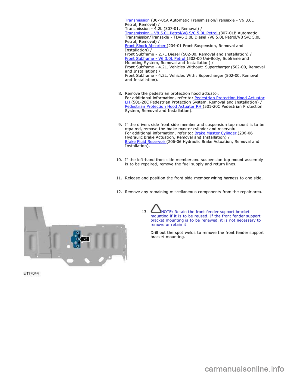
13. NOTE: Retain the front fender support bracket
mounting if it is to be reused. If the front fender support
bracket mounting is to be renewed, it is not necessary to
remove or retain it.
Drill out the spot welds to remove the front fender support
bracket mounting.
Page 2797 of 3039
(100-00 General Information, Description and Operation) /
Body Repairs (501-25A Body Repairs - General Information, Description and Operation) /
Corrosion Protection (501-25B Body Repairs - Corrosion Protection, Description and Operation) /
Body and Frame (501-26 Body Repairs - Vehicle Specific Information and Tolerance Checks, Description and Operation).
5. Remove the fender apron panel front extension.
For additional information, refer to: Fender Apron Panel Front Extension (501-27 Front End Sheet Metal Repairs, Removal and Installation).
6. Remove the front fender support bracket.
For additional information, refer to: Front Fender Support Bracket (501-27 Front End Sheet Metal Repairs, Removal and Installation).
7. Remove the fender apron panel.
For additional information, refer to: Fender Apron Panel (501-27 Front End Sheet Metal Repairs, Removal and Installation).
8. Remove the engine, transmission / transaxle, front subframe and front
suspension, as an assembly.
For additional information, refer to: Engine (303-01A, Removal) /
Engine (303-01B Engine - V6 3.0L Petrol, Removal) / Engine (303-01D, Removal) /
Engine (303-01E, Removal) /
Transmission - 2.7L Diesel (307-01, Removal) /
Transmission - TDV6 3.0L Diesel (307-01B Automatic Transmission/Transaxle - TDV6 3.0L Diesel /V8 5.0L Petrol/V8 S/C 5.0L
Petrol, Removal) /
Transmission (307-01A Automatic Transmission/Transaxle - V6 3.0L Petrol, Removal) /
Transmission - 4.2L (307-01, Removal) /
Transmission - V8 5.0L Petrol/V8 S/C 5.0L Petrol (307-01B Automatic Transmission/Transaxle - TDV6 3.0L Diesel /V8 5.0L Petrol/V8 S/C 5.0L
Petrol, Removal) /
Front Shock Absorber (204-01 Front Suspension, Removal and Installation) /
Front Subframe - 2.7L Diesel (502-00, Removal and Installation) /
Front Subframe - V6 3.0L Petrol (502-00 Uni-Body, Subframe and Mounting System, Removal and Installation) /
Front Subframe - 4.2L, Vehicles Without: Supercharger (502-00, Removal
and Installation) /
Front Subframe - 4.2L, Vehicles With: Supercharger (502-00, Removal
and Installation).
9. Remove the pedestrian protection hood actuator.
For additional information, refer to: Pedestrian Protection Hood Actuator LH (501-20C Pedestrian Protection System, Removal and Installation) / Pedestrian Protection Hood Actuator RH (501-20C Pedestrian Protection System, Removal and Installation).
10. If the drivers side front side member and suspension top mount is to be
repaired, remove the brake master cylinder and reservoir.
For additional information, refer to: Brake Master Cylinder (206-06 Hydraulic Brake Actuation, Removal and Installation) /
Brake Fluid Reservoir (206-06 Hydraulic Brake Actuation, Removal and Installation).
11. If the drivers side front side member and suspension top mount is to be
repaired, remove the brake booster.