2010 JAGUAR XFR wheel
[x] Cancel search: wheelPage 2470 of 3039
8. Refer to: Floor Console (501-12 Instrument Panel and Console, Removal and Installation).
9. Refer to: Glove Compartment (501-12 Instrument Panel and Console, Removal and Installation).
10. Refer to: Instrument Panel Lower Trim Panel (501-12 Instrument Panel and Console, Removal and Installation).
11. Refer to: A-Pillar Trim Panel (501-05 Interior Trim and Ornamentation, Removal and Installation).
12. Refer to: Cowl Side Trim Panel (501-05 Interior Trim and Ornamentation, Removal and Installation).
13. Refer to: Steering Wheel (211-04 Steering Column, Removal and Installation).
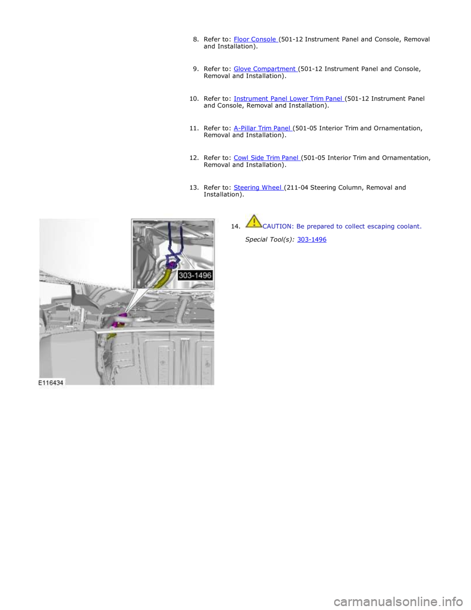
14. CAUTION: Be prepared to collect escaping coolant.
Special Tool(s): 303-1496
Page 2537 of 3039
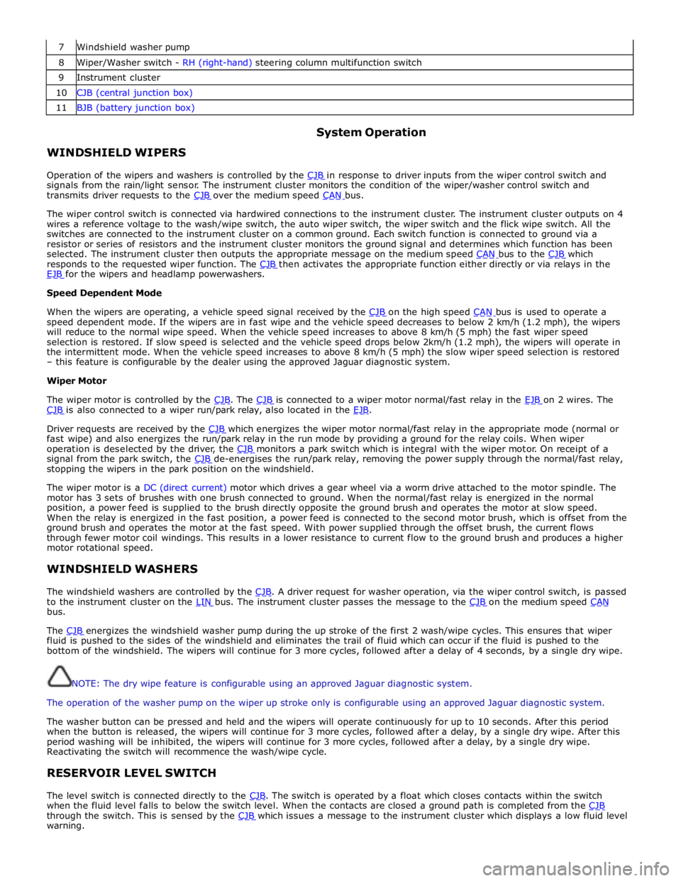
7 Windshield washer pump 8 Wiper/Washer switch - RH (right-hand) steering column multifunction switch 9 Instrument cluster 10 CJB (central junction box) 11 BJB (battery junction box)
WINDSHIELD WIPERS System Operation
Operation of the wipers and washers is controlled by the CJB in response to driver inputs from the wiper control switch and signals from the rain/light sensor. The instrument cluster monitors the condition of the wiper/washer control switch and
transmits driver requests to the CJB over the medium speed CAN bus.
The wiper control switch is connected via hardwired connections to the instrument cluster. The instrument cluster outputs on 4
wires a reference voltage to the wash/wipe switch, the auto wiper switch, the wiper switch and the flick wipe switch. All the
switches are connected to the instrument cluster on a common ground. Each switch function is connected to ground via a
resistor or series of resistors and the instrument cluster monitors the ground signal and determines which function has been
selected. The instrument cluster then outputs the appropriate message on the medium speed CAN bus to the CJB which responds to the requested wiper function. The CJB then activates the appropriate function either directly or via relays in the EJB for the wipers and headlamp powerwashers. Speed Dependent Mode
When the wipers are operating, a vehicle speed signal received by the CJB on the high speed CAN bus is used to operate a speed dependent mode. If the wipers are in fast wipe and the vehicle speed decreases to below 2 km/h (1.2 mph), the wipers
will reduce to the normal wipe speed. When the vehicle speed increases to above 8 km/h (5 mph) the fast wiper speed
selection is restored. If slow speed is selected and the vehicle speed drops below 2km/h (1.2 mph), the wipers will operate in
the intermittent mode. When the vehicle speed increases to above 8 km/h (5 mph) the slow wiper speed selection is restored
– this feature is configurable by the dealer using the approved Jaguar diagnostic system.
Wiper Motor
The wiper motor is controlled by the CJB. The CJB is connected to a wiper motor normal/fast relay in the EJB on 2 wires. The CJB is also connected to a wiper run/park relay, also located in the EJB.
Driver requests are received by the CJB which energizes the wiper motor normal/fast relay in the appropriate mode (normal or fast wipe) and also energizes the run/park relay in the run mode by providing a ground for the relay coils. When wiper
operation is deselected by the driver, the CJB monitors a park switch which is integral with the wiper motor. On receipt of a signal from the park switch, the CJB de-energises the run/park relay, removing the power supply through the normal/fast relay, stopping the wipers in the park position on the windshield.
The wiper motor is a DC (direct current) motor which drives a gear wheel via a worm drive attached to the motor spindle. The
motor has 3 sets of brushes with one brush connected to ground. When the normal/fast relay is energized in the normal
position, a power feed is supplied to the brush directly opposite the ground brush and operates the motor at slow speed.
When the relay is energized in the fast position, a power feed is connected to the second motor brush, which is offset from the
ground brush and operates the motor at the fast speed. With power supplied through the offset brush, the current flows
through fewer motor coil windings. This results in a lower resistance to current flow to the ground brush and produces a higher
motor rotational speed.
WINDSHIELD WASHERS
The windshield washers are controlled by the CJB. A driver request for washer operation, via the wiper control switch, is passed to the instrument cluster on the LIN bus. The instrument cluster passes the message to the CJB on the medium speed CAN bus.
The CJB energizes the windshield washer pump during the up stroke of the first 2 wash/wipe cycles. This ensures that wiper fluid is pushed to the sides of the windshield and eliminates the trail of fluid which can occur if the fluid is pushed to the
bottom of the windshield. The wipers will continue for 3 more cycles, followed after a delay of 4 seconds, by a single dry wipe.
NOTE: The dry wipe feature is configurable using an approved Jaguar diagnostic system.
The operation of the washer pump on the wiper up stroke only is configurable using an approved Jaguar diagnostic system.
The washer button can be pressed and held and the wipers will operate continuously for up to 10 seconds. After this period
when the button is released, the wipers will continue for 3 more cycles, followed after a delay, by a single dry wipe. After this
period washing will be inhibited, the wipers will continue for 3 more cycles, followed after a delay, by a single dry wipe.
Reactivating the switch will recommence the wash/wipe cycle.
RESERVOIR LEVEL SWITCH
The level switch is connected directly to the CJB. The switch is operated by a float which closes contacts within the switch when the fluid level falls to below the switch level. When the contacts are closed a ground path is completed from the CJB through the switch. This is sensed by the CJB which issues a message to the instrument cluster which displays a low fluid level warning.
Page 2541 of 3039
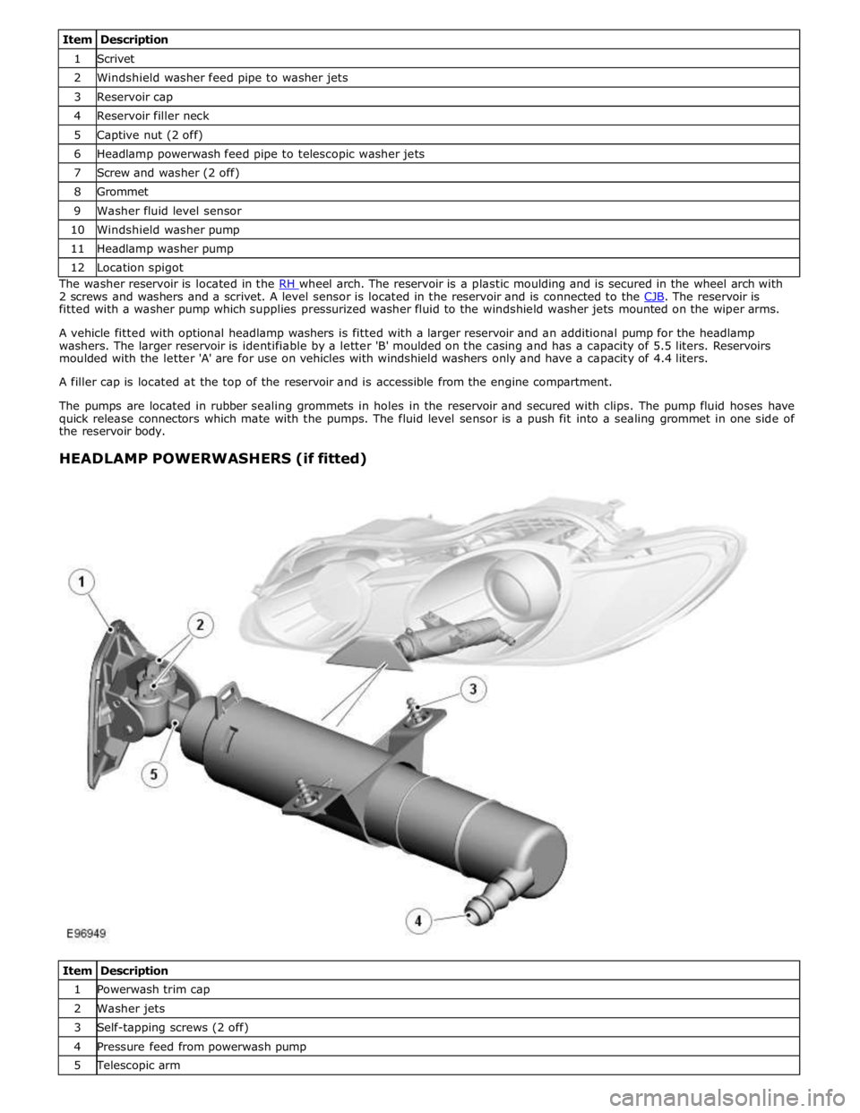
1 Scrivet 2 Windshield washer feed pipe to washer jets 3 Reservoir cap 4 Reservoir filler neck 5 Captive nut (2 off) 6 Headlamp powerwash feed pipe to telescopic washer jets 7 Screw and washer (2 off) 8 Grommet 9 Washer fluid level sensor 10 Windshield washer pump 11 Headlamp washer pump 12 Location spigot The washer reservoir is located in the RH wheel arch. The reservoir is a plastic moulding and is secured in the wheel arch with 2 screws and washers and a scrivet. A level sensor is located in the reservoir and is connected to the CJB. The reservoir is fitted with a washer pump which supplies pressurized washer fluid to the windshield washer jets mounted on the wiper arms.
A vehicle fitted with optional headlamp washers is fitted with a larger reservoir and an additional pump for the headlamp
washers. The larger reservoir is identifiable by a letter 'B' moulded on the casing and has a capacity of 5.5 liters. Reservoirs
moulded with the letter 'A' are for use on vehicles with windshield washers only and have a capacity of 4.4 liters.
A filler cap is located at the top of the reservoir and is accessible from the engine compartment.
The pumps are located in rubber sealing grommets in holes in the reservoir and secured with clips. The pump fluid hoses have
quick release connectors which mate with the pumps. The fluid level sensor is a push fit into a sealing grommet in one side of
the reservoir body.
HEADLAMP POWERWASHERS (if fitted)
Item Description 1 Powerwash trim cap 2 Washer jets 3 Self-tapping screws (2 off) 4 Pressure feed from powerwash pump 5 Telescopic arm
Page 2542 of 3039
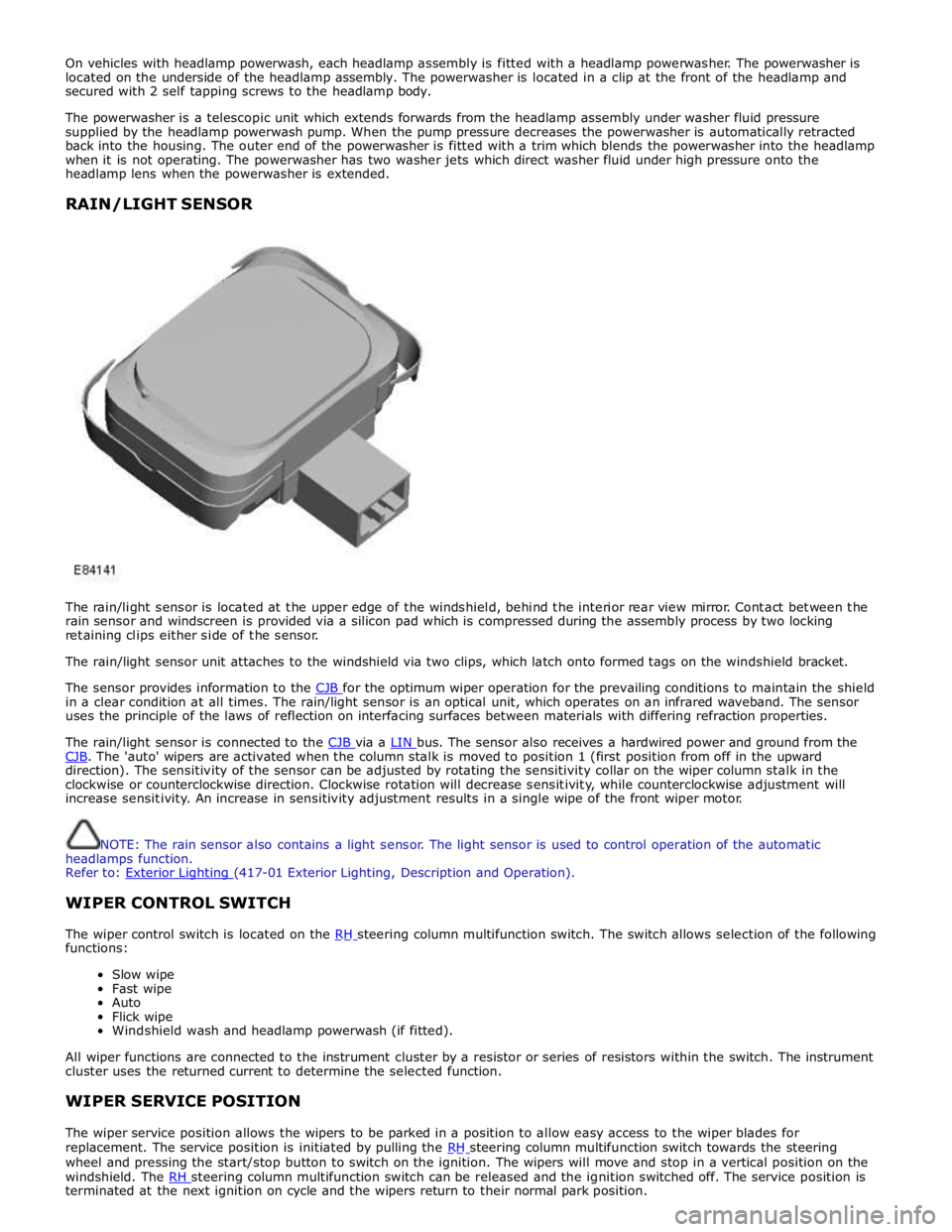
On vehicles with headlamp powerwash, each headlamp assembly is fitted with a headlamp powerwasher. The powerwasher is
located on the underside of the headlamp assembly. The powerwasher is located in a clip at the front of the headlamp and
secured with 2 self tapping screws to the headlamp body.
The powerwasher is a telescopic unit which extends forwards from the headlamp assembly under washer fluid pressure
supplied by the headlamp powerwash pump. When the pump pressure decreases the powerwasher is automatically retracted
back into the housing. The outer end of the powerwasher is fitted with a trim which blends the powerwasher into the headlamp
when it is not operating. The powerwasher has two washer jets which direct washer fluid under high pressure onto the
headlamp lens when the powerwasher is extended.
RAIN/LIGHT SENSOR
The rain/light sensor is located at the upper edge of the windshield, behind the interior rear view mirror. Contact between the
rain sensor and windscreen is provided via a silicon pad which is compressed during the assembly process by two locking
retaining clips either side of the sensor.
The rain/light sensor unit attaches to the windshield via two clips, which latch onto formed tags on the windshield bracket.
The sensor provides information to the CJB for the optimum wiper operation for the prevailing conditions to maintain the shield in a clear condition at all times. The rain/light sensor is an optical unit, which operates on an infrared waveband. The sensor
uses the principle of the laws of reflection on interfacing surfaces between materials with differing refraction properties.
The rain/light sensor is connected to the CJB via a LIN bus. The sensor also receives a hardwired power and ground from the CJB. The 'auto' wipers are activated when the column stalk is moved to position 1 (first position from off in the upward direction). The sensitivity of the sensor can be adjusted by rotating the sensitivity collar on the wiper column stalk in the
clockwise or counterclockwise direction. Clockwise rotation will decrease sensitivity, while counterclockwise adjustment will
increase sensitivity. An increase in sensitivity adjustment results in a single wipe of the front wiper motor.
NOTE: The rain sensor also contains a light sensor. The light sensor is used to control operation of the automatic
headlamps function.
Refer to: Exterior Lighting (417-01 Exterior Lighting, Description and Operation).
WIPER CONTROL SWITCH
The wiper control switch is located on the RH steering column multifunction switch. The switch allows selection of the following functions:
Slow wipe
Fast wipe
Auto
Flick wipe
Windshield wash and headlamp powerwash (if fitted).
All wiper functions are connected to the instrument cluster by a resistor or series of resistors within the switch. The instrument
cluster uses the returned current to determine the selected function.
WIPER SERVICE POSITION
The wiper service position allows the wipers to be parked in a position to allow easy access to the wiper blades for
replacement. The service position is initiated by pulling the RH steering column multifunction switch towards the steering wheel and pressing the start/stop button to switch on the ignition. The wipers will move and stop in a vertical position on the
windshield. The RH steering column multifunction switch can be released and the ignition switched off. The service position is terminated at the next ignition on cycle and the wipers return to their normal park position.
Page 2596 of 3039
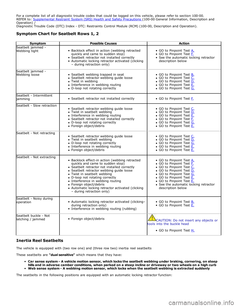
For a complete list of all diagnostic trouble codes that could be logged on this vehicle, please refer to section 100-00.
REFER to: Supplemental Restraint System (SRS) Health and Safety Precautions (100-00 General Information, Description and Operation) /
Diagnostic Trouble Code (DTC) Index - DTC: Restraints Control Module (RCM) (100-00, Description and Operation).
Symptom Chart for Seatbelt Rows 1, 2
Symptom Possible Causes Action Seatbelt jammed -
Webbing tight
Backlock effect in action (webbing retracted
quickly and came to sudden stop)
Seatbelt retractor not installed correctly
Automatic locking retractor activated (clicking
– during retraction only)
GO to Pinpoint Test A. GO to Pinpoint Test F. See the automatic locking retractor
description below Seatbelt jammed -
Seatbelt webbing trapped in seat
GO to Pinpoint Test B. Webbing loose Seatbelt retractor webbing guide loose GO to Pinpoint Test C. Twist in webbing GO to Pinpoint Test D. Interference in webbing routing GO to Pinpoint Test E. D-loop not rotating correctly GO to Pinpoint Test G. Seatbelt - Intermittent jamming
Seatbelt retractor not installed correctly
GO to Pinpoint Test F. Seatbelt - Slow retraction
Seatbelt retractor webbing guide loose
GO to Pinpoint Test C. Twist in seatbelt webbing GO to Pinpoint Test D. Interference in webbing routing GO to Pinpoint Test E. Seatbelt retractor not installed correctly GO to Pinpoint Test F. D-loop not rotating correctly GO to Pinpoint Test G. Foreign object/debris GO to Pinpoint Test E. Seatbelt - Not retracting
Seatbelt retractor webbing guide loose
GO to Pinpoint Test C. Twist in seatbelt webbing GO to Pinpoint Test D. D-loop not rotating correctly GO to Pinpoint Test G. Interference in webbing routing GO to Pinpoint Test E. Foreign object/debris GO to Pinpoint Test E. Seatbelt - Not extracting
Backlock effect-in action (webbing retracted
GO to Pinpoint Test A. quickly and came to sudden stop) GO to Pinpoint Test F. Seatbelt retractor not installed correctly GO to Pinpoint Test C. Seatbelt retractor webbing guide loose GO to Pinpoint Test D. Twist in seatbelt webbing GO to Pinpoint Test G. D-loop not rotating correctly GO to Pinpoint Test E. Interference in webbing routing GO to Pinpoint Test E. Foreign object/debris See the automatic locking retractor Automatic locking retractor activated (clicking description below – during retraction only) Seatbelt - Noisy during
operation
Automatic locking retractor activated (clicking–
during retraction only)
Interference in webbing routing (rubbing)
GO to Pinpoint Test B. GO to Pinpoint Test E. Seatbelt buckle - Not
latching / jammed
Foreign object/debris
CAUTION: Do not insert any objects or
tools into the buckle head
GO to Pinpoint Test H.
Inertia Reel Seatbelts
The vehicle is equipped with (two row one) and (three row two) inertia reel seatbelts
These seatbelts are "dual sensitive" which means that they have:
Car sense system - A vehicle motion sensor, which locks the seatbelt webbing under braking, cornering, on steep
hills and in adverse camber conditions, when parked on a steep incline or driveway or two wheels on a high curb
Web sense system - A webbing motion sensor, which locks when the seatbelt webbing is extracted suddenly
The seatbelts in the following positions are equipped with an automatic locking retractor function:
Page 2616 of 3039
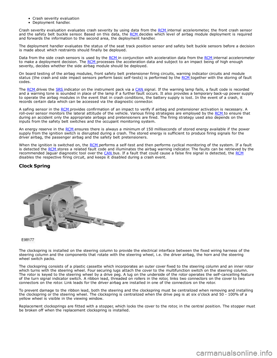
and the safety belt buckle sensor. Based on this data, the RCM decides which level of airbag module deployment is required and forwards the information to the second area, the deployment handler.
The deployment handler evaluates the status of the seat track position sensor and safety belt buckle sensors before a decision
is made about which restraints should finally be deployed.
Data from the side crash sensors is used by the RCM in conjunction with acceleration data from the RCM internal accelerometer to make a deployment decision. The RCM processes the acceleration data and subject to an impact being of high enough severity, decides whether the side airbag module should be deployed.
On board testing of the airbag modules, front safety belt pretensioner firing circuits, warning indicator circuits and module
status (the crash and side impact sensors perform basic self-tests) is performed by the RCM together with the storing of fault codes.
The RCM drives the SRS indicator on the instrument pack via a CAN signal. If the warning lamp fails, a fault code is recorded and a warning tone is sounded in place of the lamp if a further fault occurs. It also provides a temporary back-up power supply
to operate the airbag modules in the event that in crash conditions, the battery supply is lost. In the event of a crash, it
records certain data which can be accessed via the diagnostic connector.
A safing sensor in the RCM provides confirmation of an impact to verify if airbag and pretensioner activation is necessary. A roll-over sensor monitors the lateral attitude of the vehicle. Various firing strategies are employed by the RCM to ensure that during an accident only the appropriate airbags and pretensioners are fired. The firing strategy used also depends on the
inputs from the safety belt switches and the occupant monitoring system.
An energy reserve in the RCM ensures there is always a minimum of 150 milliseconds of stored energy available if the power supply from the ignition switch is disrupted during a crash. The stored energy is sufficient to produce firing signals for the
driver airbag, the passenger airbag and the safety belt pretensioners.
When the ignition is switched on, the RCM performs a self-test and then performs cyclical monitoring of the system. If a fault is detected the RCM stores a related fault code and illuminates the airbag warning indicator. The faults can be retrieved by the recommended Jaguar diagnostic tool over the CAN bus. If a fault that could cause a false fire signal is detected, the RCM disables the respective firing circuit, and keeps it disabled during a crash event.
Clock Spring
The clockspring is installed on the steering column to provide the electrical interface between the fixed wiring harness of the
steering column and the components that rotate with the steering wheel, i.e. the driver airbag, the horn and the steering
wheel switch packs.
The clockspring consists of a plastic cassette which incorporates an outer cover fixed to the steering column and an inner rotor
which turns with the steering wheel. Four securing lugs attach the cover to the multifunction switch on the steering column.
The rotor is keyed to the steering wheel by a drive peg. A lug on the underside of the rotor operates the self-cancelling feature
of the turn signal indicator switch. A ribbon lead, threaded on rollers in the rotor, links two connectors on the cover to two
connectors on the rotor. Link leads for the driver airbag are installed in one of the connectors on the rotor.
To prevent damage to the ribbon lead, both the steering and the clockspring must be centralized when removing and installing
the clockspring or the steering wheel. The clockspring is centralized when the drive peg is at six o'clock and 50 - 100% of a
yellow wheel is visible in the viewing window.
Replacement clocksprings are fitted with a stopper, which locks the cover to the rotor, in the central position. The stopper must
be broken off when the replacement clockspring is installed.
Page 2617 of 3039
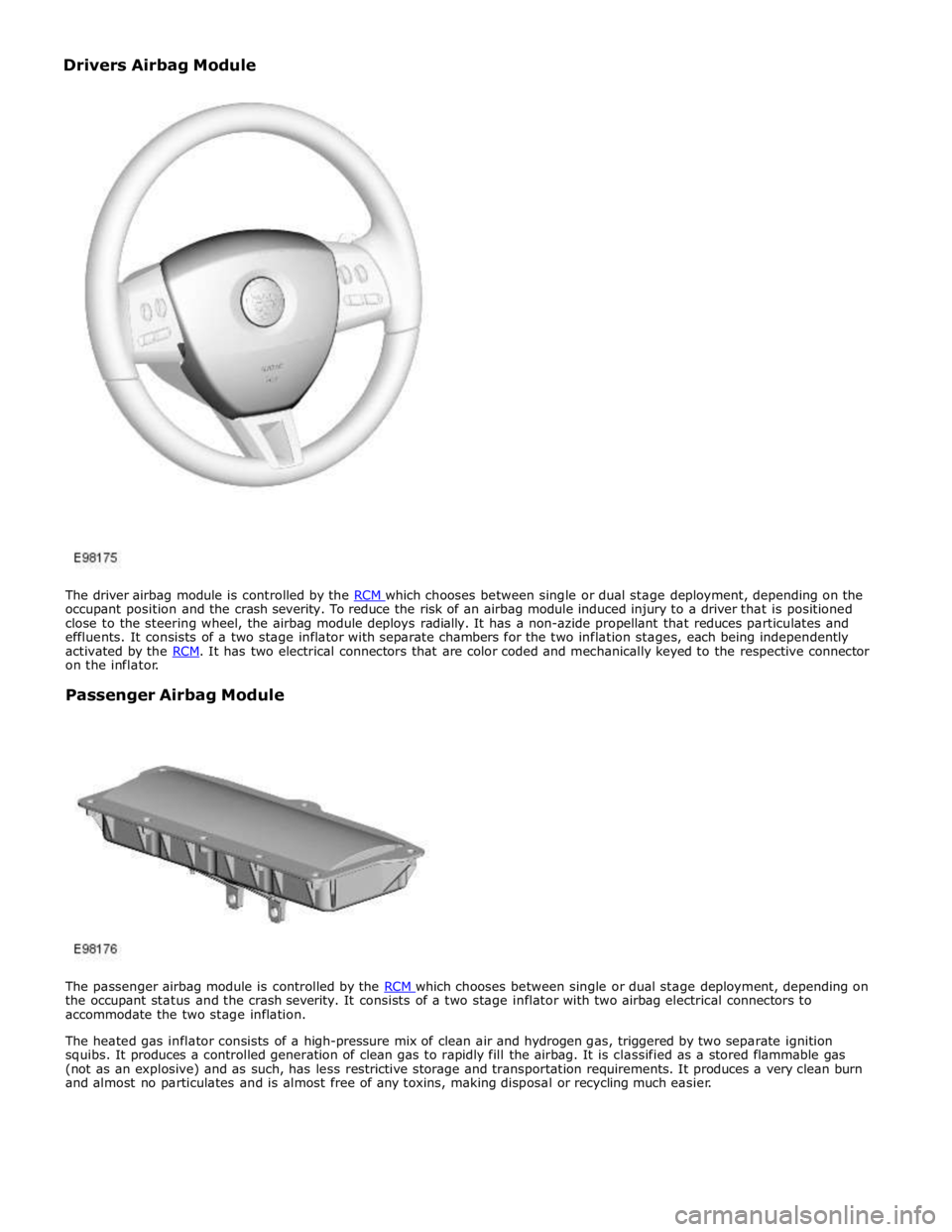
occupant position and the crash severity. To reduce the risk of an airbag module induced injury to a driver that is positioned
close to the steering wheel, the airbag module deploys radially. It has a non-azide propellant that reduces particulates and
effluents. It consists of a two stage inflator with separate chambers for the two inflation stages, each being independently
activated by the RCM. It has two electrical connectors that are color coded and mechanically keyed to the respective connector on the inflator.
Passenger Airbag Module
The passenger airbag module is controlled by the RCM which chooses between single or dual stage deployment, depending on the occupant status and the crash severity. It consists of a two stage inflator with two airbag electrical connectors to
accommodate the two stage inflation.
The heated gas inflator consists of a high-pressure mix of clean air and hydrogen gas, triggered by two separate ignition
squibs. It produces a controlled generation of clean gas to rapidly fill the airbag. It is classified as a stored flammable gas
(not as an explosive) and as such, has less restrictive storage and transportation requirements. It produces a very clean burn
and almost no particulates and is almost free of any toxins, making disposal or recycling much easier. Drivers Airbag Module
Page 2629 of 3039
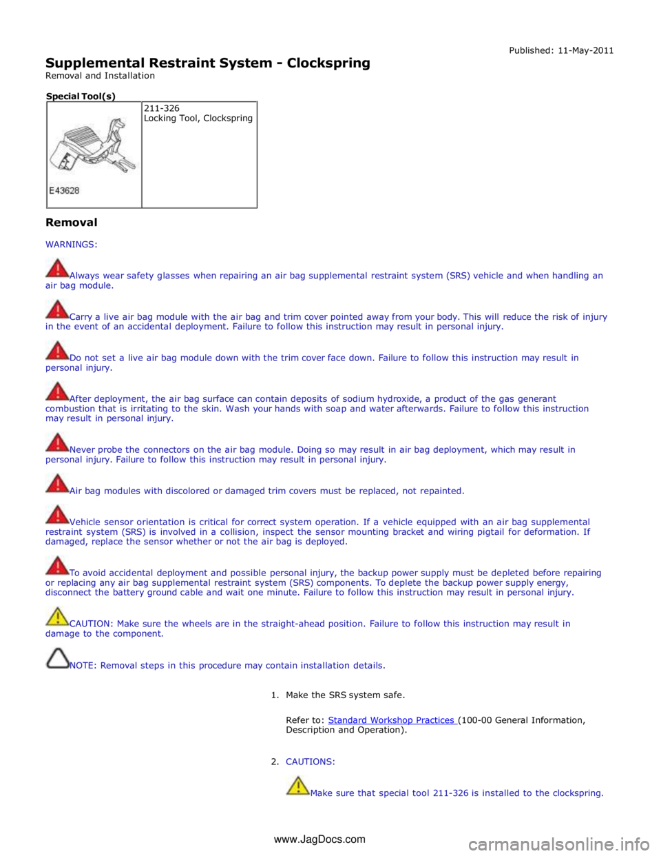
Supplemental Restraint System - Clockspring
Removal and Installation Published: 11-May-2011
Removal
WARNINGS:
Always wear safety glasses when repairing an air bag supplemental restraint system (SRS) vehicle and when handling an
air bag module.
Carry a live air bag module with the air bag and trim cover pointed away from your body. This will reduce the risk of injury
in the event of an accidental deployment. Failure to follow this instruction may result in personal injury.
Do not set a live air bag module down with the trim cover face down. Failure to follow this instruction may result in
personal injury.
After deployment, the air bag surface can contain deposits of sodium hydroxide, a product of the gas generant
combustion that is irritating to the skin. Wash your hands with soap and water afterwards. Failure to follow this instruction
may result in personal injury.
Never probe the connectors on the air bag module. Doing so may result in air bag deployment, which may result in
personal injury. Failure to follow this instruction may result in personal injury.
Air bag modules with discolored or damaged trim covers must be replaced, not repainted.
Vehicle sensor orientation is critical for correct system operation. If a vehicle equipped with an air bag supplemental
restraint system (SRS) is involved in a collision, inspect the sensor mounting bracket and wiring pigtail for deformation. If
damaged, replace the sensor whether or not the air bag is deployed.
To avoid accidental deployment and possible personal injury, the backup power supply must be depleted before repairing
or replacing any air bag supplemental restraint system (SRS) components. To deplete the backup power supply energy,
disconnect the battery ground cable and wait one minute. Failure to follow this instruction may result in personal injury.
CAUTION: Make sure the wheels are in the straight-ahead position. Failure to follow this instruction may result in
damage to the component.
NOTE: Removal steps in this procedure may contain installation details.
1. Make the SRS system safe.
Refer to: Standard Workshop Practices (100-00 General Information, Description and Operation).
2. CAUTIONS:
Make sure that special tool 211-326 is installed to the clockspring. 211-326
Locking Tool, Clockspring Special Tool(s)
www.JagDocs.com