Page 1861 of 3039
Parking Aid - Front Outer Parking Aid Sensor
Removal and Installation
Removal Published: 06-Mar-2013
1. Refer to: Front Bumper Cover (501-19 Bumpers, Removal and Installation).
2.
Installation
1. CAUTION: If a new sensor is installed, make sure that the area
illustrated is the only area painted. Failure to follow this instruction may
result in the component malfunctioning.
NOTE: On vehicles that are equipped with black or unpainted
bumpers, the sensor(s) do not require painting.
Page 1891 of 3039
1 LCD screen with main menu 2 Control panel (key board and power button) 3 Positive and negative fly leads 4 Fly leads connection 5 Temperature sensor 6 Infra-red sensor (data transfer for printer) 7 Amp hour 8 Battery rating (CCA) 9 Rating units 10 Battery type
clean clamp and terminal then reconnect and repeat test GO to A2.
Page 1896 of 3039
NOTE:
TESTING
11.
Testing.
The
screen
displays
clock
hand's
rotating,
the
EXP-1080
will
automatically
advance
when
test
has
completed
NOTES:
TEMPERATURE
Ensurethatthetemperaturesensordoesnottouchanypartofthebatteryorvehicle,thiswillcausedamagenotbe
coveredunderthemidtronicswarrantyand willrequiretheunittobereturnedtoaservicecenter
10.Temperature.Aimthetemperaturesensortowardsthebatterycasing (Maintaindistanceof5cm)
SelectNext
Page 1951 of 3039

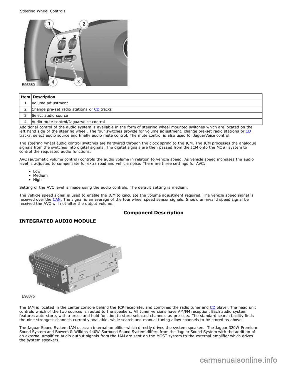
1 Volume adjustment 2 Change pre-set radio stations or CD tracks 3 Select audio source 4 Audio mute control/JaguarVoice control Additional control of the audio system is available in the form of steering wheel mounted switches which are located on the
left hand side of the steering wheel. The four switches provide for volume adjustment, change pre-set radio stations or CD tracks, select audio source and finally audio mute control. The mute control is also used for JaguarVoice control.
The steering wheel audio control switches are hardwired through the clock spring to the ICM. The ICM processes the analogue
signals from the switches into digital signals. The digital signals are then passed from the ICM onto the MOST system to
control the requested audio functions.
AVC (automatic volume control) controls the audio volume in relation to vehicle speed. As vehicle speed increases the audio
level is adjusted to compensate for extra road and vehicle noise. There are three settings for AVC:
Low
Medium
High
Setting of the AVC level is made using the audio controls. The default setting is medium.
The vehicle speed signal is used to enable the ICM to calculate the volume adjustment required. The vehicle speed signal is
received over the CAN. The signal is an average of the four wheel speed sensor signals. Should an invalid speed signal be received the AVC will not alter the output volume.
INTEGRATED AUDIO MODULE Component Description
The IAM is located in the center console behind the ICP faceplate, and combines the radio tuner and CD player. The head unit controls which of the two sources is routed to the speakers. All tuner versions have AM/FM reception. Each audio system
features auto-store, with a press and hold function to store selected channels as pre-sets. The standard search facility finds
the nine strongest channels currently available, while search and manual tuning allow channels to be stored as above.
The Jaguar Sound System IAM uses an internal amplifier which directly drives the system speakers. The Jaguar 320W Premium
Sound System and Bowers & Wilkins 440W Surround Sound System differs from the Jaguar Sound System with the addition of
an external amplifier. Audio output signals from the IAM are sent on the MOST system to the external amplifier which drives
the system speakers.
Page 1979 of 3039

VICS (vehicle information and communication system) receiver (Japan only)
TMC (traffic message channel) receiver (Europe only)
JaguarVoice control module
The navigation computer contains a solid state piezo gyro which measures the motion of the vehicle around its vertical axis.
The gyro operates on the principle known as the coriolis force. The coriolis force is the force that appears to accelerate a body
moving away from its rotational axis against the direction of rotation of the axis.
Using inputs from the ABS module, the GPS antenna and the gyro sensor, the computer calculates the vehicle's current position, direction and speed.
The navigation computer houses the DVD (digital versatile disc) drive. The drive is used to read map data from region specific
DVD's. The number of DVD's issued per region varies depending on the amount of information available. The regions are as follows:
Europe (2 versions, Western Europe and Whole of Europe)
NAS (North American specification)
Japan, Middle East, Australia and South Africa
A button, located adjacent to the DVD slot, is provided to eject the DVD from the unit. Prior to ejecting the disc the slot protection has to be slid to the side. If the ignition is on, or the entertainment system is in 1-hour mode, one press of the
button will eject the DVD.
The navigation computer uses non-volatile memory to store settings and configuration information when it is powered down.
This process takes place just before the computer turns off.
No configuration procedure is required if the navigation computer is replaced. There is no option to calibrate the navigation
computer using the Jaguar approved diagnostic equipment; however in some regions a software download, contained in the
DVD disc, is required before the navigation system becomes operational.
MICROPHONE
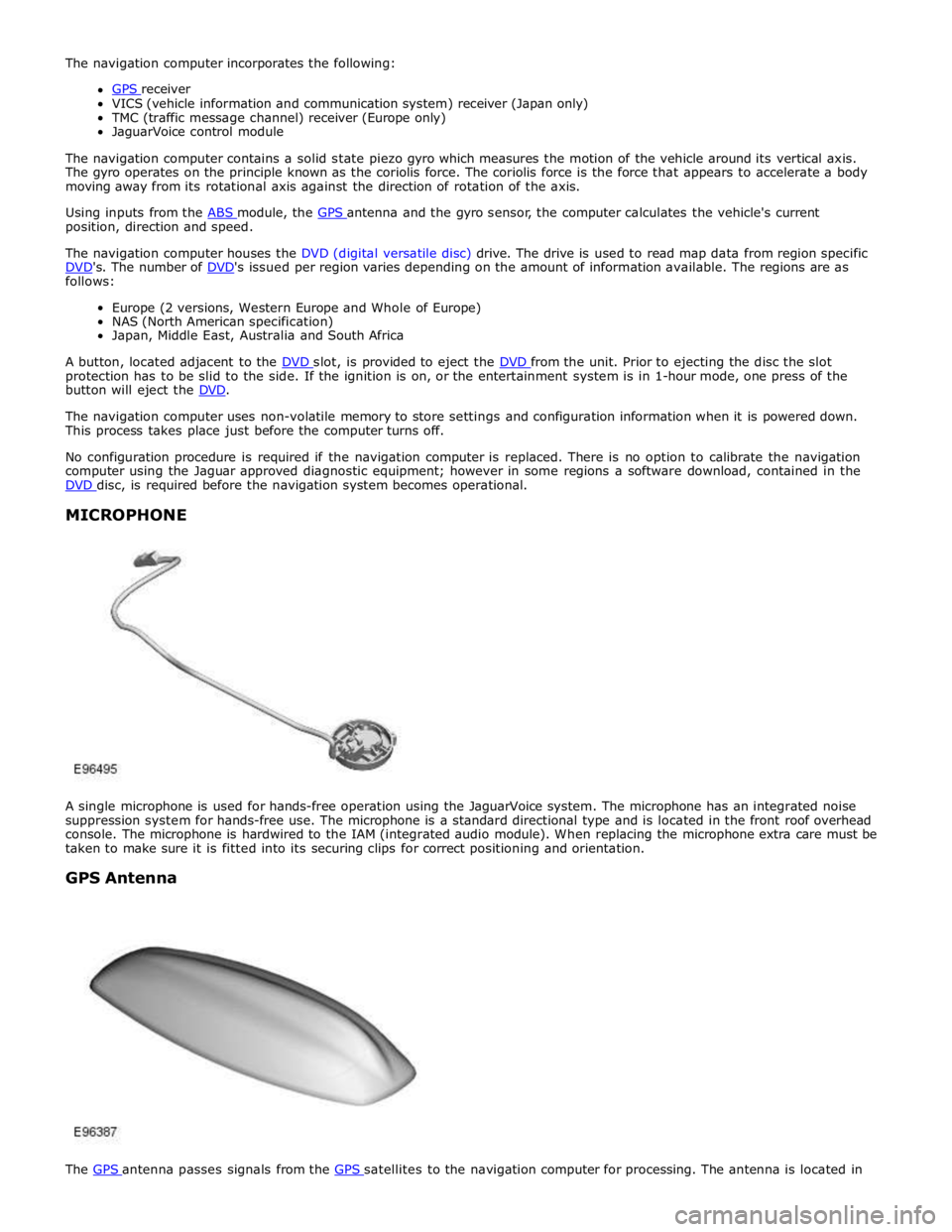
A single microphone is used for hands-free operation using the JaguarVoice system. The microphone has an integrated noise
suppression system for hands-free use. The microphone is a standard directional type and is located in the front roof overhead
console. The microphone is hardwired to the IAM (integrated audio module). When replacing the microphone extra care must be
taken to make sure it is fitted into its securing clips for correct positioning and orientation.
GPS Antenna
The GPS antenna passes signals from the GPS satellites to the navigation computer for processing. The antenna is located in
Page 2020 of 3039
1 Front height sensor 2 Headlamp leveling module 3 Rain/light sensor 4 Rear height sensor 5 Light switch - LH (left-hand) steering column multifunction switch 6 Auxiliary lighting switch 7 Side marker lamp (NAS only) (2 off) 8 Front turn signal indicator (2 off) 9 Halogen or xenon headlamp projector module (2 off) 10 Cornering/Static bending lamp (where fitted) (2 off) www.JagDocs.com
Page 2022 of 3039

The lighting system has an 'auto' lights function which is controlled by the CJB on receipt of signals from the rain/light sensor located at the top of the windscreen. The exterior lights are turned on or off in response to ambient light signals from the
rain/light sensor on a LIN (local interconnect network) bus connection to the CJB . The auto lights can also be activated when the windshield wipers are activated by signals from the rain sensor, which is located at the top of the windshield or when the
driver activates the wipers in the fast wipe position.
Two levels of headlamp specification are available; halogen or xenon. In certain markets the headlamps feature a cornering
lamp or a static bending lamp which illuminates the area at the side of the vehicle when turning into driveways for example.
North American Specification (NAS) vehicles have a side marker lamp installed in the headlamp assembly. Replacement of any
of the headlamp bulbs requires removal of the headlamp assembly.
The tail lamp comprises two separate lamp assemblies. The turn signal indicator, side and stop lamps and reverse lamps are
located in each rear fender tail lamp assembly. The rear fog lamps are located in separate units attached to the luggage
compartment lid. A side marker lamp is fitted to the rear fender tail lamp assembly and is fitted in all markets.
Two systems of headlamp leveling are available; manual leveling which is only available on halogen headlamps and static
dynamic leveling which is available on xenon headlamps. The manual system uses a thumbwheel rheostat to adjust the
vertical alignment of the headlamps to compensate for differing vehicle loading. The static dynamic system uses height
sensors fitted to the front and rear suspension and a headlamp leveling module which periodically monitors the vehicle
attitude and adjusts the headlamp vertical alignment accordingly.
Page 2024 of 3039
8 Rear height sensor 9 RH (right-hand) headlamp assembly 10 LH (left-hand) headlamp assembly 11 Lighting control switch - LH steering column multifunction switch 12 Instrument cluster HALOGEN HEADLAMPS - CONTROL DIAGRAM
Item Description A = Hardwired; N = Medium speed CAN bus 1 Battery 2 BJB 3 CJB 4 EJB 5 Auxiliary lighting switch