2010 JAGUAR XFR wheel alignment
[x] Cancel search: wheel alignmentPage 589 of 3039
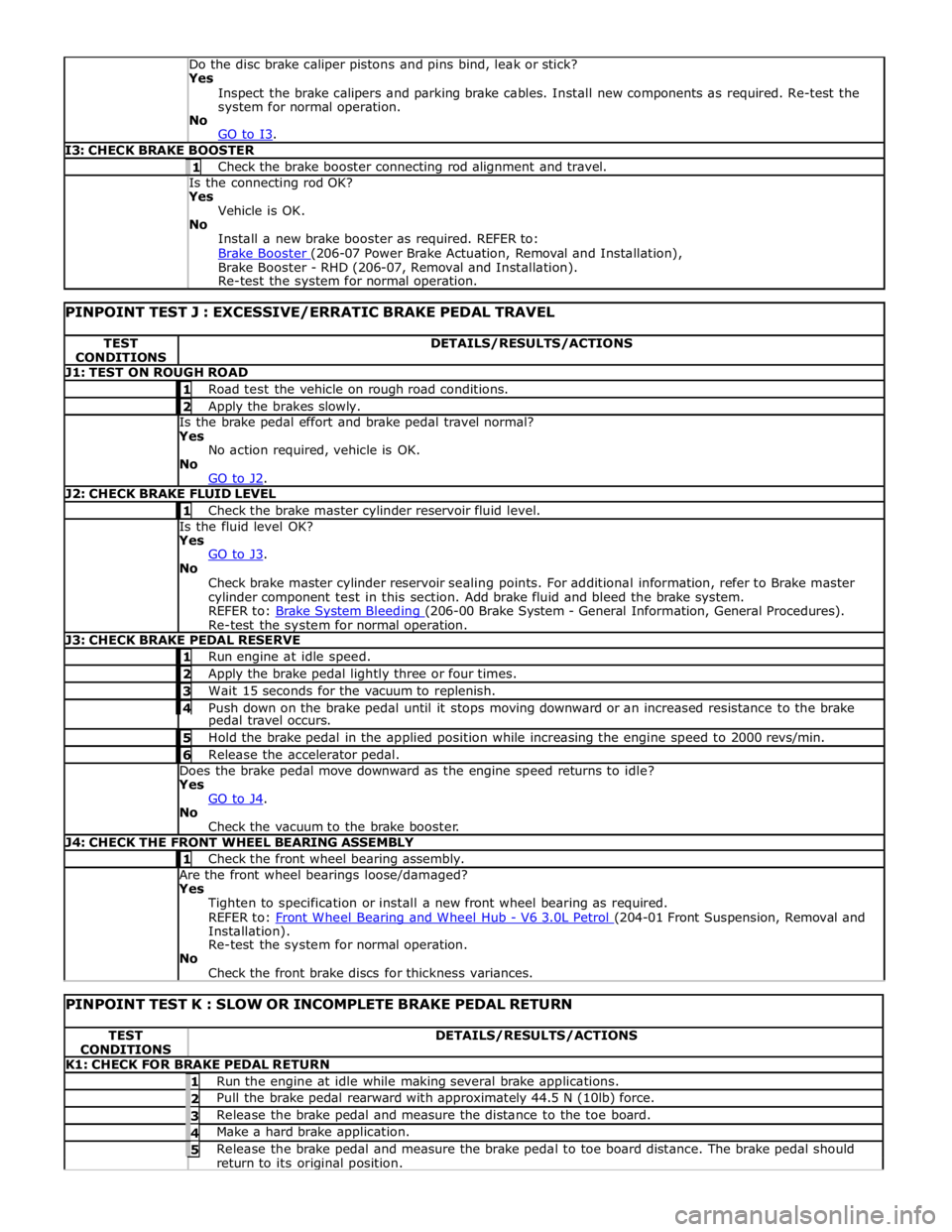
Yes
Inspect the brake calipers and parking brake cables. Install new components as required. Re-test the
system for normal operation.
No
GO to I3. I3: CHECK BRAKE BOOSTER 1 Check the brake booster connecting rod alignment and travel. Is the connecting rod OK? Yes
Vehicle is OK.
No
Install a new brake booster as required. REFER to:
Brake Booster (206-07 Power Brake Actuation, Removal and Installation), Brake Booster - RHD (206-07, Removal and Installation).
Re-test the system for normal operation.
PINPOINT TEST J : EXCESSIVE/ERRATIC BRAKE PEDAL TRAVEL TEST
CONDITIONS DETAILS/RESULTS/ACTIONS J1: TEST ON ROUGH ROAD 1 Road test the vehicle on rough road conditions. 2 Apply the brakes slowly. Is the brake pedal effort and brake pedal travel normal?
Yes
No action required, vehicle is OK.
No
GO to J2. J2: CHECK BRAKE FLUID LEVEL 1 Check the brake master cylinder reservoir fluid level. Is the fluid level OK?
Yes
GO to J3. No
Check brake master cylinder reservoir sealing points. For additional information, refer to Brake master
cylinder component test in this section. Add brake fluid and bleed the brake system.
REFER to: Brake System Bleeding (206-00 Brake System - General Information, General Procedures). Re-test the system for normal operation. J3: CHECK BRAKE PEDAL RESERVE 1 Run engine at idle speed. 2 Apply the brake pedal lightly three or four times. 3 Wait 15 seconds for the vacuum to replenish. 4 Push down on the brake pedal until it stops moving downward or an increased resistance to the brake pedal travel occurs. 5 Hold the brake pedal in the applied position while increasing the engine speed to 2000 revs/min. 6 Release the accelerator pedal. Does the brake pedal move downward as the engine speed returns to idle?
Yes
GO to J4. No
Check the vacuum to the brake booster. J4: CHECK THE FRONT WHEEL BEARING ASSEMBLY 1 Check the front wheel bearing assembly. Are the front wheel bearings loose/damaged?
Yes
Tighten to specification or install a new front wheel bearing as required.
REFER to: Front Wheel Bearing and Wheel Hub - V6 3.0L Petrol (204-01 Front Suspension, Removal and Installation).
Re-test the system for normal operation.
No
Check the front brake discs for thickness variances.
PINPOINT TEST K : SLOW OR INCOMPLETE BRAKE PEDAL RETURN TEST
CONDITIONS DETAILS/RESULTS/ACTIONS K1: CHECK FOR BRAKE PEDAL RETURN 1 Run the engine at idle while making several brake applications. 2 Pull the brake pedal rearward with approximately 44.5 N (10lb) force. 3 Release the brake pedal and measure the distance to the toe board. 4 Make a hard brake application. 5 Release the brake pedal and measure the brake pedal to toe board distance. The brake pedal should return to its original position.
Page 719 of 3039

Symptom Possible Causes Action
Damaged fluid
cap/reservoir
Check and install a new fluid cap/reservoir as required
Loose or damaged
hoses and fittings
O-ring or Dowty seals
Tighten the hose connection or latch plate fixing to the
recommended torque.
REFER to: Specifications (211-00 Steering System - General Information, Specifications).
Check and install new components as required
Install new O-ring or Dowty seals as required
Fluid cooler
Check and install a new fluid cooler as required, refer to the new
module/component installation note at the top of the Symptom
Charts
Power steering pump
Check and install a new power steering pump as required, refer to
the new module/component installation note at the top of the
Symptom Charts Functional
Symptom Possible Causes Action
Steering wheel
misalignment
Steering not correctly centred
Check the steering alignment.
REFER to: Specifications (204-00 Suspension System - General
Information, Specifications).
Excessive free play at
steering wheel (refer to
the Steering Linkage
Inspection and Backlash
(Free play) Check in this
section)
Steering wheel loose
Check and tighten the steering
wheel retaining bolt as required.
REFER to: Specifications (211-00 Steering System - General
Information, Specifications).
Excess play in the steering linkage
Check and install new
components as required
Steering gear not correctly adjusted (causing
excessive backlash)
CAUTION: DO NOT attempt to
adjust the steering gear yoke. Failure to
follow this instruction will invalidate the
steering gear warranty
Check and install a new steering
gear as required, refer to the
new module/component
installation note at the top of
the Symptom Charts
Lower steering column universal joint pinch
bolts loose
Check and tighten the lower
steering column pinch bolts as
required.
REFER to: Specifications (211-00 Steering System - General
Information, Specifications).
Excessive wear in steering column universal
joints
Check and install a new steering
column or steering column lower
shaft as required, refer to the
new module/component
installation note at the top of
the Symptom Charts
Steering gear mounting bolts loose or
damaged
Check/tighten and install new
steering gear mounting bolts as
required.
REFER to: Specifications (211-00 Steering System - General
Information, Specifications). www.JagDocs.com
Page 721 of 3039
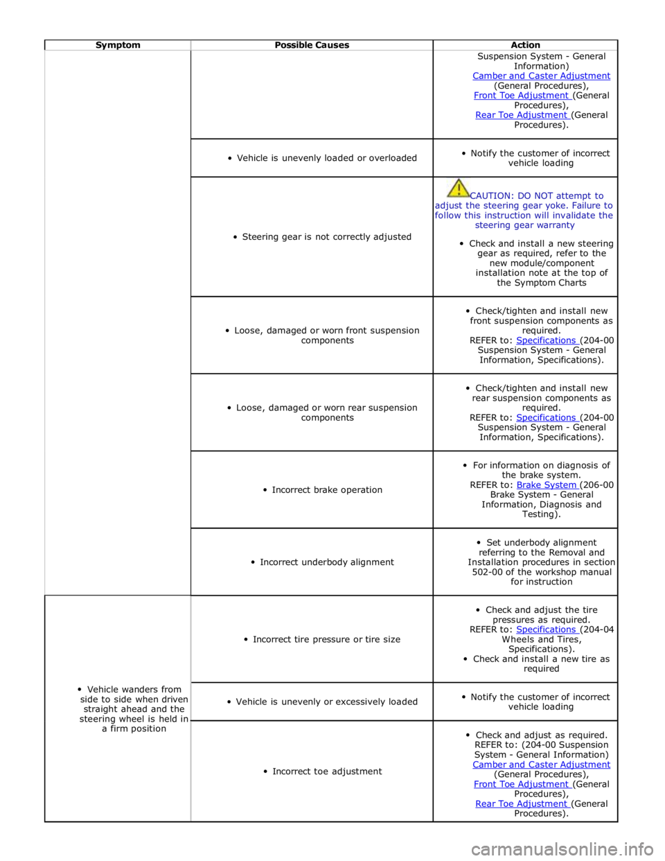
Symptom Possible Causes Action Suspension System - General
Information)
Camber and Caster Adjustment (General Procedures),
Front Toe Adjustment (General Procedures),
Rear Toe Adjustment (General Procedures).
Vehicle is unevenly loaded or overloaded
Notify the customer of incorrect
vehicle loading
Steering gear is not correctly adjusted
CAUTION: DO NOT attempt to
adjust the steering gear yoke. Failure to
follow this instruction will invalidate the
steering gear warranty
Check and install a new steering
gear as required, refer to the
new module/component
installation note at the top of
the Symptom Charts
Loose, damaged or worn front suspension
components
Check/tighten and install new
front suspension components as
required.
REFER to: Specifications (204-00 Suspension System - General
Information, Specifications).
Loose, damaged or worn rear suspension
components
Check/tighten and install new
rear suspension components as
required.
REFER to: Specifications (204-00 Suspension System - General
Information, Specifications).
Incorrect brake operation
For information on diagnosis of
the brake system.
REFER to: Brake System (206-00 Brake System - General
Information, Diagnosis and
Testing).
Incorrect underbody alignment
Set underbody alignment
referring to the Removal and
Installation procedures in section
502-00 of the workshop manual
for instruction
Vehicle wanders from
side to side when driven
straight ahead and the
steering wheel is held in
a firm position
Incorrect tire pressure or tire size
Check and adjust the tire
pressures as required.
REFER to: Specifications (204-04 Wheels and Tires,
Specifications).
Check and install a new tire as
required
Vehicle is unevenly or excessively loaded
Notify the customer of incorrect
vehicle loading
Incorrect toe adjustment
Check and adjust as required.
REFER to: (204-00 Suspension
System - General Information)
Camber and Caster Adjustment (General Procedures),
Front Toe Adjustment (General Procedures),
Rear Toe Adjustment (General Procedures).
Page 753 of 3039

Power Steering - Steering Gear
Removal and Installation Published: 04-Jul-2013
CAUTIONS: Removal
Make sure that only the manufacturers' recommended four wheel alignment equipment is used.
Do not turn the steering wheel with the steering column lower shaft disconnected as damage to the clockspring and
steering wheel switches may occur.
NOTES:
Make sure the steering is in the straight ahead position.
RHD illustration shown, LHD is similar.
Some variation in the illustrations may occur, but the essential information is always correct.
1. Raise and support the vehicle.
2. Center the steering wheel.
Lock in position and remove the ignition key.
3. Remove the front wheels and tires.
For additional information, refer to: Wheel and Tire (204-04 Wheels and Tires, Removal and Installation).
4. Remove the air deflector.
For additional information, refer to: Air Deflector (501-02 Front End Body Panels, Removal and Installation).
Page 774 of 3039

Installation
1. Install the tie rod end, note the number of turns until adjacent to the
locknut.
2. CAUTION: Make sure that the ball joint ball does not rotate.
Connect the tie-rod end ball joint.
Clean the component mating faces.
Install a new nut and tighten to 133 Nm.
3. Tighten the tie-rod locking nut.
Clean the component mating faces.
Tighten the nut to 55 Nm.
4. Install the front wheel.
For additional information, refer to: Wheel and Tire (204-04 Wheels and Tires, Removal and Installation).
5. Using only four-wheel alignment equipment approved by Jaguar, check
and adjust the wheel alignment.
For additional information, refer to: Four-Wheel Alignment (204-00 Suspension System - General Information, General Procedures).
Page 795 of 3039
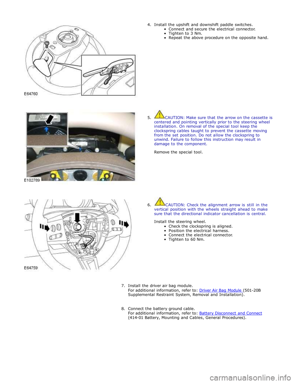
4. Install the upshift and downshift paddle switches.
Connect and secure the electrical connector.
Tighten to 3 Nm.
Repeat the above procedure on the opposite hand.
5. CAUTION: Make sure that the arrow on the cassette is
centered and pointing vertically prior to the steering wheel
installation. On removal of the special tool keep the
clockspring cables taught to prevent the cassette moving
from the set position. Do not allow the clockspring to
unwind. Failure to follow this instruction may result in
damage to the component.
Remove the special tool.
6. CAUTION: Check the alignment arrow is still in the
vertical position with the wheels straight ahead to make
sure that the directional indicator cancellation is central.
Install the steering wheel.
Check the clockspring is aligned.
Position the electrical harness.
Connect the electrical connector.
Tighten to 60 Nm.
7. Install the driver air bag module.
For additional information, refer to: Driver Air Bag Module (501-20B Supplemental Restraint System, Removal and Installation).
8. Connect the battery ground cable.
For additional information, refer to: Battery Disconnect and Connect (414-01 Battery, Mounting and Cables, General Procedures).
Page 1644 of 3039
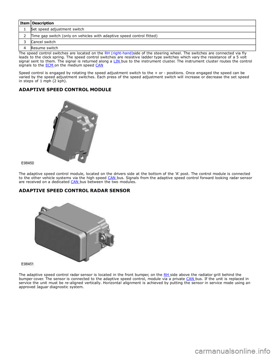
1 Set speed adjustment switch 2 Time gap switch (only on vehicles with adaptive speed control fitted) 3 Cancel switch 4 Resume switch The speed control switches are located on the RH (right-hand)side of the steering wheel. The switches are connected via fly
leads to the clock spring. The speed control switches are resistive ladder type switches which vary the resistance of a 5 volt
signal sent to them. The signal is returned along a LIN bus to the instrument cluster. The instrument cluster routes the control signals to the ECM on the medium speed CAN
Speed control is engaged by rotating the speed adjustment switch to the + or - positions. Once engaged the speed can be
varied by the speed adjustment switches. Each press of the speed adjustment switch will increase or decrease the set speed
in steps of 1 mph (2 kph).
ADAPTIVE SPEED CONTROL MODULE
The adaptive speed control module, located on the drivers side at the bottom of the 'A' post. The control module is connected
to the other vehicle systems via the high speed CAN bus. Signals from the adaptive speed control forward looking radar sensor are received on a dedicated CAN bus between the two modules.
ADAPTIVE SPEED CONTROL RADAR SENSOR
The adaptive speed control radar sensor is located in the front bumper, on the RH side above the radiator grill behind the bumper cover. The sensor is connected to the adaptive speed control, module via a private CAN bus. If the unit is replaced in service the unit must be re-aligned vertically. Horizontal alignment is achieved by putting the sensor in service mode using an
approved Jaguar diagnostic system.
Page 1646 of 3039
Published: 08-Nov-2013
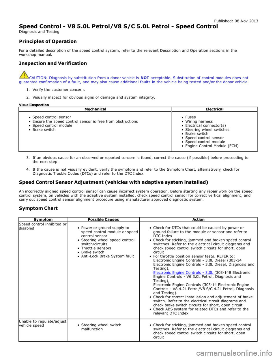
Speed Control - V8 5.0L Petrol/V8 S/C 5.0L Petrol - Speed Control
Diagnosis and Testing
Principles of Operation
For a detailed description of the speed control system, refer to the relevant Description and Operation sections in the
workshop manual.
Inspection and Verification
CAUTION: Diagnosis by substitution from a donor vehicle is NOT acceptable. Substitution of control modules does not
guarantee confirmation of a fault, and may also cause additional faults in the vehicle being tested and/or the donor vehicle.
1. Verify the customer concern.
2. Visually inspect for obvious signs of damage and system integrity.
Visual Inspection
Mechanical Electrical
Speed control sensor
Ensure the speed control sensor is free from obstructions
Speed control module
Brake switch
Fuses
Wiring harness
Electrical connector(s)
Steering wheel switches
Brake switch
Speed control sensor
Speed control module
Engine Control Module (ECM)
3. If an obvious cause for an observed or reported concern is found, correct the cause (if possible) before proceeding to
the next step.
4. If the cause is not visually evident, verify the symptom and refer to the Symptom Chart, alternatively, check for
Diagnostic Trouble Codes (DTCs) and refer to the DTC Index.
Speed Control Sensor Adjustment (vehicles with adaptive system installed)
An incorrectly aligned speed control sensor can cause incorrect system operation. Before starting any repair work on the speed
control system, on vehicles with the adaptive system installed, check speed control sensor for correct vertical alignment, and
carry out speed control sensor alignment procedure using manufacturer approved diagnostic system.
Symptom Chart
Symptom Possible Causes Action Speed control inhibited or
disabled
Power or ground supply to
speed control module or speed
control sensor
Steering wheel speed control
switch/circuits
Throttle sensors
Brake switch
Anti-Lock Brake System fault
Check for DTCs that could be caused by power or
ground failure to the module or sensor and refer to
DTC Index
Check for sticking, jammed and broken speed control
switches. Refer to the electrical circuit diagrams and
check speed control switch circuits for short, open
circuit
For throttle position sensor tests. REFER to:
Electronic Engine Controls - 3.0L Diesel (303-14
Electronic Engine Controls - 3.0L Diesel, Diagnosis and
Testing),
Electronic Engine Controls - 3.0L (303-14B Electronic Engine Controls - V6 3.0L Petrol, Diagnosis and
Testing),
Electronic Engine Controls (303-14 Electronic Engine
Controls - V8 4.2L Petrol/V8 S/C 4.2L Petrol, Diagnosis
and Testing).
Check for correct installation and adjustment of brake
switch. Refer to the electrical circuit diagrams and
check brake switch circuits for short, open circuit
Check ABS system for related DTCs and refer to the
relevant DTC Index Unable to regulate/adjust
vehicle speed
Steering wheel switch
malfunction
Check for sticking, jammed and broken speed control
switches. Refer to the electrical circuit diagrams and
check speed control switch circuits for short, open
circuit