2010 JAGUAR XFR navigation system
[x] Cancel search: navigation systemPage 1979 of 3039
VICS (vehicle information and communication system) receiver (Japan only)
TMC (traffic message channel) receiver (Europe only)
JaguarVoice control module
The navigation computer contains a solid state piezo gyro which measures the motion of the vehicle around its vertical axis.
The gyro operates on the principle known as the coriolis force. The coriolis force is the force that appears to accelerate a body
moving away from its rotational axis against the direction of rotation of the axis.
Using inputs from the ABS module, the GPS antenna and the gyro sensor, the computer calculates the vehicle's current position, direction and speed.
The navigation computer houses the DVD (digital versatile disc) drive. The drive is used to read map data from region specific
DVD's. The number of DVD's issued per region varies depending on the amount of information available. The regions are as follows:
Europe (2 versions, Western Europe and Whole of Europe)
NAS (North American specification)
Japan, Middle East, Australia and South Africa
A button, located adjacent to the DVD slot, is provided to eject the DVD from the unit. Prior to ejecting the disc the slot protection has to be slid to the side. If the ignition is on, or the entertainment system is in 1-hour mode, one press of the
button will eject the DVD.
The navigation computer uses non-volatile memory to store settings and configuration information when it is powered down.
This process takes place just before the computer turns off.
No configuration procedure is required if the navigation computer is replaced. There is no option to calibrate the navigation
computer using the Jaguar approved diagnostic equipment; however in some regions a software download, contained in the
DVD disc, is required before the navigation system becomes operational.
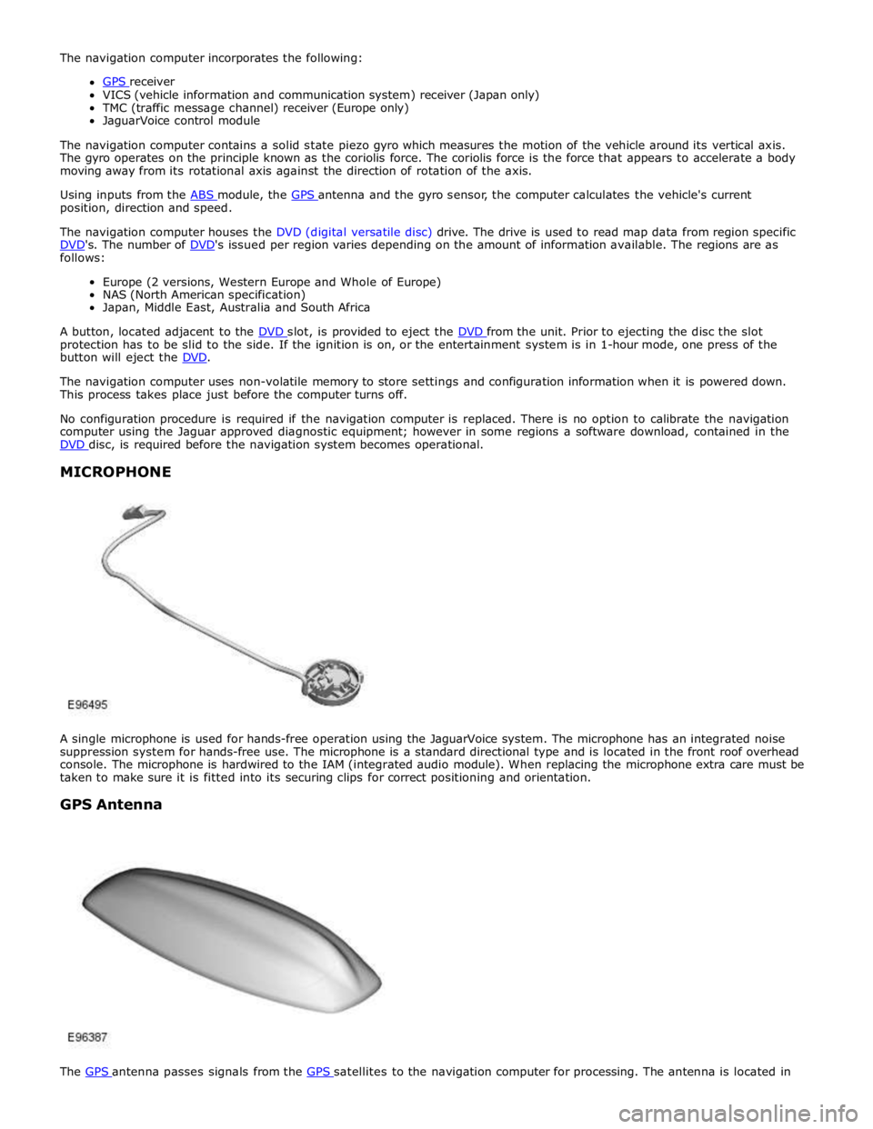
MICROPHONE
A single microphone is used for hands-free operation using the JaguarVoice system. The microphone has an integrated noise
suppression system for hands-free use. The microphone is a standard directional type and is located in the front roof overhead
console. The microphone is hardwired to the IAM (integrated audio module). When replacing the microphone extra care must be
taken to make sure it is fitted into its securing clips for correct positioning and orientation.
GPS Antenna
The GPS antenna passes signals from the GPS satellites to the navigation computer for processing. The antenna is located in
Page 1980 of 3039
the roof pod and is shared with the DAB (digital audio broadcasting) band L antenna or satellite radio antenna where fitted.
The roof pod is located externally in a central position towards the rear of the roof.
The GPS antenna is designed with 50 ohm output impedance. The navigation computer is fitted with 50 ohm fakra II connectors to ensure compatibility with the antenna. For optimum performance 50 ohm low loss coaxial cable is used between
the antenna and navigation computer.
It is possible for the GPS antenna to lose the signal from the GPS satellites; In hilly or tree lined areas
Built up areas with tall buildings
In multi storey car parks
In garages
In tunnels
On bridges
During heavy rain or thunderstorms
When the signal is lost the navigation computer will continue to give guidance using memory mapped data from the DVD map until the signal is restored.
TMC/VICS FM Antenna
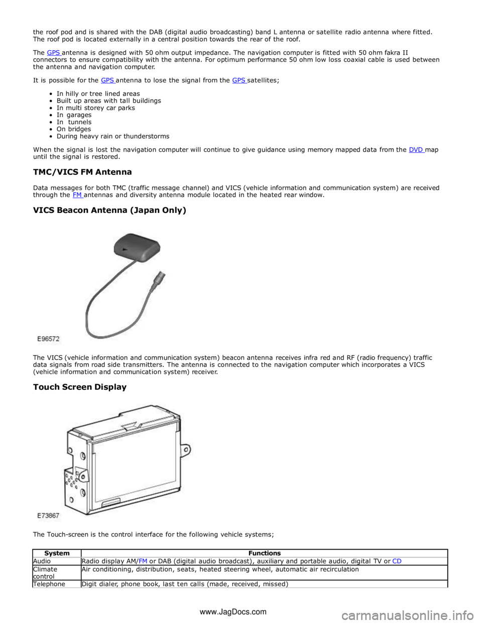
Data messages for both TMC (traffic message channel) and VICS (vehicle information and communication system) are received
through the FM antennas and diversity antenna module located in the heated rear window.
VICS Beacon Antenna (Japan Only)
The VICS (vehicle information and communication system) beacon antenna receives infra red and RF (radio frequency) traffic
data signals from road side transmitters. The antenna is connected to the navigation computer which incorporates a VICS
(vehicle information and communication system) receiver.
Touch Screen Display
The Touch-screen is the control interface for the following vehicle systems;
System Functions Audio Radio display AM/FM or DAB (digital audio broadcast), auxiliary and portable audio, digital TV or CD Climate
control Air conditioning, distribution, seats, heated steering wheel, automatic air recirculation Telephone Digit dialer, phone book, last ten calls (made, received, missed) www.JagDocs.com
Page 1981 of 3039
Navigation Destination, stored locations, navigation setup, route options Vehicle
Security, parking, valet mode, trip computer, clock, brightness, contrast, system settings, vehicle settings, display settings The screen is a touch sensitive 7 inch LCD (liquid crystal display) VGA screen containing 800 x 480 pixels in a 15:9 format. The
screen processes its own video for system operation but receives the navigation graphics from the navigation computer.
Steering Wheel Controls
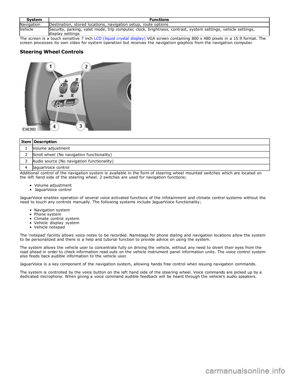
Item Description 1 Volume adjustment 2 Scroll wheel (No navigation functionality) 3 Audio source (No navigation functionality) 4 JaguarVoice control Additional control of the navigation system is available in the form of steering wheel mounted switches which are located on
the left hand side of the steering wheel. 2 switches are used for navigation functions;
Volume adjustment
JaguarVoice control
JaguarVoice enables operation of several voice activated functions of the infotainment and climate control systems without the
need to touch any controls manually. The following systems include JaguarVoice functionality;
Navigation system
Phone system
Climate control system
Vehicle display system
Vehicle notepad
The 'notepad' facility allows voice notes to be recorded. Nametags for phone dialing and navigation locations allow the system
to be personalized and there is a help and tutorial function to provide advice on using the system.
The system allows the vehicle user to concentrate fully on driving the vehicle, without any need to divert their eyes from the
road ahead in order to check information read outs on the vehicle instrument panel information units. The voice control system
also feeds back audible information to the vehicle user.
JaguarVoice is a key component of the navigation system, allowing hands free control when issuing navigation commands.
The system is controlled by the voice button on the left hand side of the steering wheel. Voice commands are picked up by a
dedicated microphone. When giving a voice command audible feedback will be heard through the vehicle’s audio speakers.
Page 1990 of 3039

Cellular Phone (Diagnosis and Testing), Navigation System (Diagnosis and Testing). www.JagDocs.com
Page 2077 of 3039
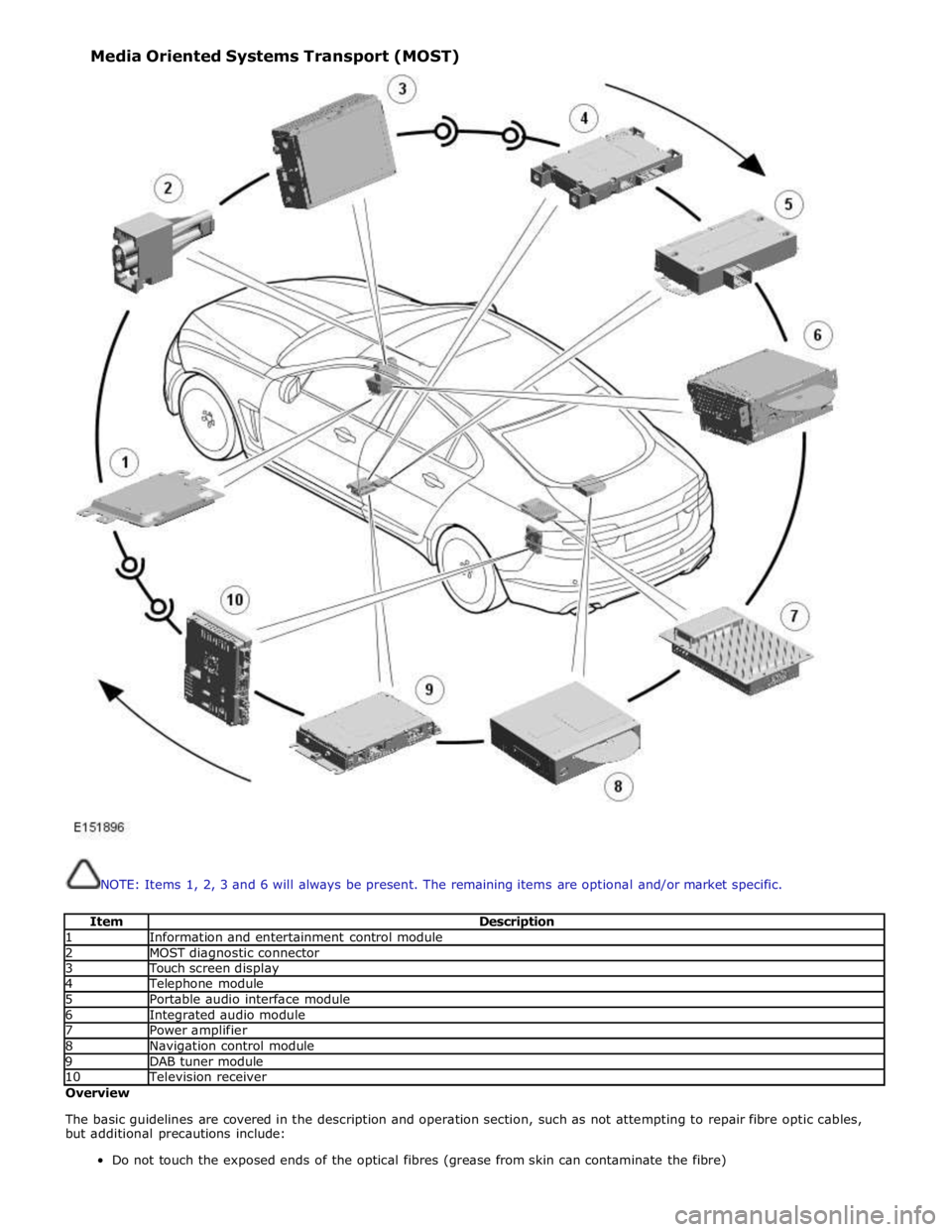
NOTE: Items 1, 2, 3 and 6 will always be present. The remaining items are optional and/or market specific.
Item Description 1 Information and entertainment control module 2 MOST diagnostic connector 3 Touch screen display 4 Telephone module 5 Portable audio interface module 6 Integrated audio module 7 Power amplifier 8 Navigation control module 9 DAB tuner module 10 Television receiver Overview
The basic guidelines are covered in the description and operation section, such as not attempting to repair fibre optic cables,
but additional precautions include:
Do not touch the exposed ends of the optical fibres (grease from skin can contaminate the fibre) Media Oriented Systems Transport (MOST)
Page 2148 of 3039

Telematics - Telematics
Diagnosis and Testing Published: 11-May-2011
The complexity of the electronics involved with the JaguarNet system, of which the GPS antenna and navigation display are
parts, and the multiplexed communication network which are connected to it preclude the use of workshop general electrical
test equipment. Therefore, reference should be made to the approved Jaguar diagnostic system for detailed instructions on
testing the VEMS unit.
The approved Jaguar diagnostic system tests and analyses all functions of the VEMS and the various systems affected by it.
Where a fault is indicated, some basic diagnostic methods may be necessary to confirm that connections are good and that
wiring is not damaged before installing a new component.
Page 2149 of 3039
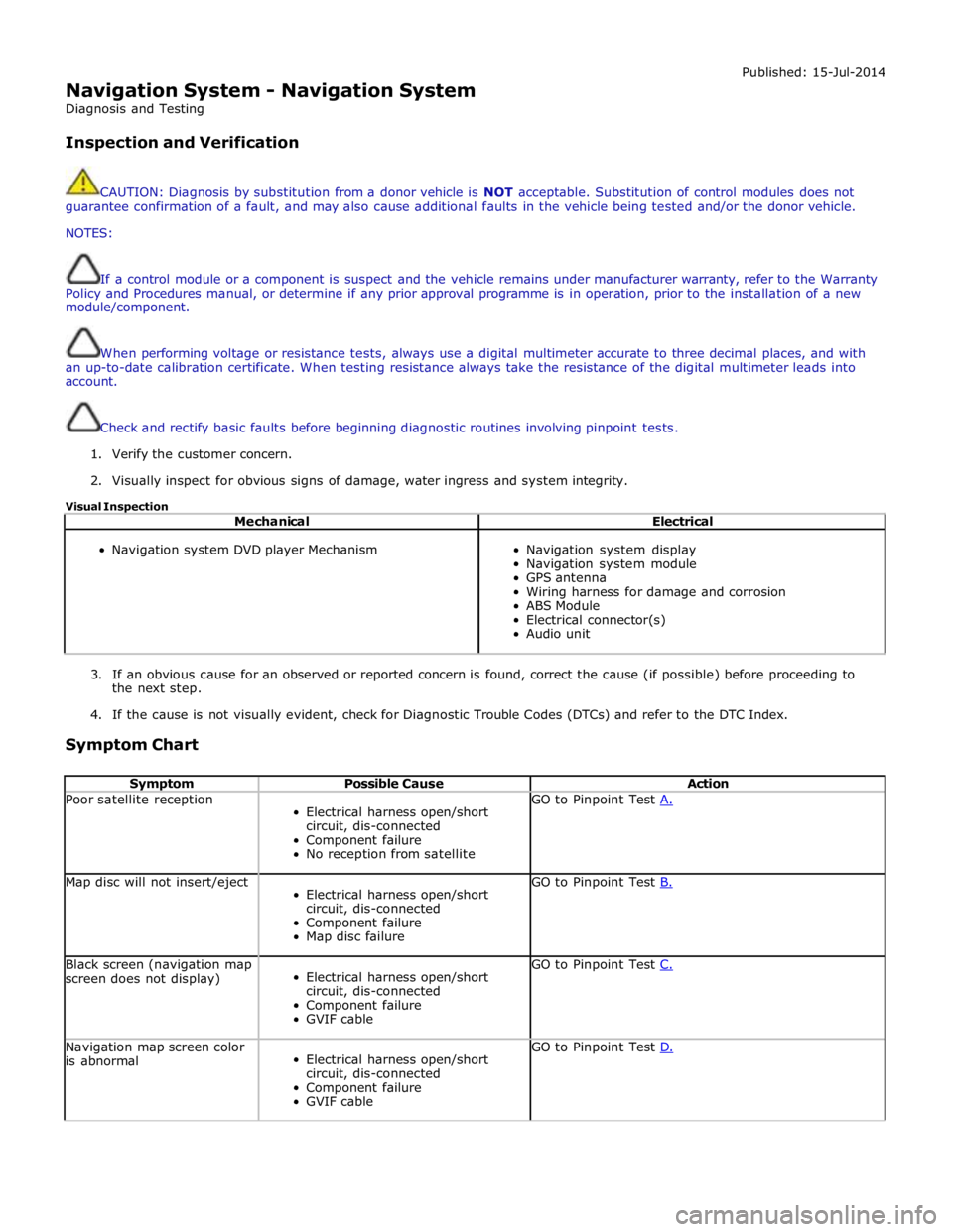
Navigation System - Navigation System
Diagnosis and Testing
Inspection and Verification Published: 15-Jul-2014
CAUTION: Diagnosis by substitution from a donor vehicle is NOT acceptable. Substitution of control modules does not
guarantee confirmation of a fault, and may also cause additional faults in the vehicle being tested and/or the donor vehicle.
NOTES:
If a control module or a component is suspect and the vehicle remains under manufacturer warranty, refer to the Warranty
Policy and Procedures manual, or determine if any prior approval programme is in operation, prior to the installation of a new
module/component.
When performing voltage or resistance tests, always use a digital multimeter accurate to three decimal places, and with
an up-to-date calibration certificate. When testing resistance always take the resistance of the digital multimeter leads into
account.
Check and rectify basic faults before beginning diagnostic routines involving pinpoint tests.
1. Verify the customer concern.
2. Visually inspect for obvious signs of damage, water ingress and system integrity.
Visual Inspection
Mechanical Electrical
Navigation system DVD player Mechanism
Navigation system display
Navigation system module
GPS antenna
Wiring harness for damage and corrosion
ABS Module
Electrical connector(s)
Audio unit
3. If an obvious cause for an observed or reported concern is found, correct the cause (if possible) before proceeding to
the next step.
4. If the cause is not visually evident, check for Diagnostic Trouble Codes (DTCs) and refer to the DTC Index.
Symptom Chart
Symptom Possible Cause Action Poor satellite reception
Electrical harness open/short
circuit, dis-connected
Component failure
No reception from satellite GO to Pinpoint Test A. Map disc will not insert/eject
Electrical harness open/short
circuit, dis-connected
Component failure
Map disc failure GO to Pinpoint Test B. Black screen (navigation map
screen does not display)
Electrical harness open/short
circuit, dis-connected
Component failure
GVIF cable GO to Pinpoint Test C. Navigation map screen color
is abnormal
Electrical harness open/short
circuit, dis-connected
Component failure
GVIF cable GO to Pinpoint Test D.
Page 2150 of 3039
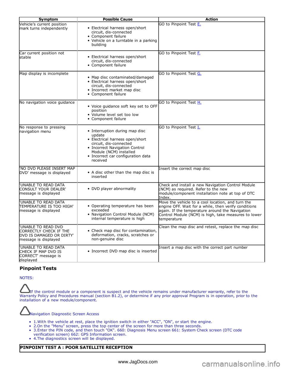
Symptom Possible Cause Action Vehicle’s current position
mark turns independently
Electrical harness open/short
circuit, dis-connected
Component failure
Vehicle on a turntable in a parking
building GO to Pinpoint Test E. Car current position not
stable
Electrical harness open/short
circuit, dis-connected
Component failure GO to Pinpoint Test F. Map display is incomplete
Map disc contaminated/damaged
Electrical harness open/short
circuit, dis-connected
Incorrect market map disc
Component failure GO to Pinpoint Test G. No navigation voice guidance
Voice guidance soft key set to OFF
position
Volume level set too low
Component failure GO to Pinpoint Test H. No response to pressing
navigation menu
Interruption during map disc
update
Electrical harness open/short
circuit, dis-connected
Incorrect Navigation Control
Module (NCM) installed
Incorrect car configuration data
received GO to Pinpoint Test I. 'NO DVD PLEASE INSERT MAP
DVD' message is displayed
A disc other than the map disc is
inserted Insert the correct map disc 'UNABLE TO READ DATA
CONSULT YOUR DEALER'
message is displayed
DVD player abnormality Check and install a new Navigation Control Module
(NCM) as required. Refer to the new
module/component installation note at top of DTC
Index. 'UNABLE TO READ DATA TEMPERATURE IS TOO HIGH'
message is displayed
Operating temperature has been
exceeded
Navigation Control Module (NCM)
internal temperature is high Move the vehicle to a cool location, and turn the
engine OFF. Wait for a while, then verify conditions
again. If the temperature around the Navigation
Control Module (NCM) is high, take measures to lower
temperature 'UNABLE TO READ DVD
CORRECTLY CHECK IF THE
DVD IS DAMAGED OR DIRTY'
message is displayed
Check map disc for contamination,
deformation, cracks, scratches or
non-genuine disc Clean the map disc and retest, replace the map disc 'UNABLE TO READ DATA
CHECK IF MAP DVD IS
CORRECT' message is displayed
Incorrect DVD map disc is inserted Insert a map disc with the correct part number Pinpoint Tests
NOTES:
If the control module or a component is suspect and the vehicle remains under manufacturer warranty, refer to the
Warranty Policy and Procedures manual (section B1.2), or determine if any prior approval Program is in operation, prior to the
installation of a new module/component.
Navigation Diagnostic Screen Access
1. With the vehicle at rest, place the ignition switch in either "ACC", "ON", or start the engine.
2.On the "Menu" screen, press the top center of the screen for more than three seconds.
3. Enter the PIN code, and then touch "OK". 660: Diagnosis Menu screen 661: System Check screen (DTC code
verification screen) 662: GPS Information screen.
4. The diagnostics screen will be displayed.
PINPOINT TEST A : POOR SATELLITE RECEPTION www.JagDocs.com