2010 JAGUAR XFR fuses
[x] Cancel search: fusesPage 1871 of 3039

Published: 21-Dec-2012
Battery and Charging System - General Information - Quiescent Drain
Description and Operation
VEHICLE QUIESCENT CURRENT TESTING
On vehicles fitted with a Battery Monitoring System (BMS), the diagnostic routine for quiescent drain testing in the approved
Jaguar or Land Rover diagnostic system should be utilized.
If a customer complains of a vehicle battery that discharges continuously or when left for a prolonged period of time, it is
recommended that a quiescent drain test is performed as described below.
The battery drain should be measured using the approved Jaguar or Land Rover diagnostic system or a Digital Multi-Meter
(DVOM). A procedure for quiescent drain measurement using the diagnostic system is available in the Diagnosis and Testing
section of the Workshop Manual. The vehicle should be in the locked/armed state (for example vehicle alarm fully armed), all
doors, engine and luggage compartment lids are open and latched (so as to appear closed from an electrical point of view).
The test should take place after the vehicle has entered shutdown mode. The time taken for this to occur after the ignition is
switched off varies according to model (Refer to the Topix On line resource for details).
When the vehicle is armed, the effect of the security system Light Emitting Diode (LED) flashing is to cause a pulsation in the
measured current drain. In this case, either the average current should be taken (using a Digital Multi- Meter (DVOM) with an
averaging system) or the current reading taken, ignoring the brief high current peaks.
EQUIPMENT
Approved Jaguar or Land Rover diagnostic system with current probeOR Digital Multi-Meter (DVOM) with current probe.
METHOD OF MEASUREMENT
Using an Approved Jaguar or Land Rover Diagnostic System.
1. Switch off all electrical loads and ensure that the ignition is off
2. Connect the current probe to the approved Jaguar or Land Rover diagnostic system
3. Calibrate the probe
4. Install a clamp around the battery lead/junction box lead
5. Go to the Quiescent Current Testing section in this procedure
Using a digital multimeter
Do not use an in-line DVOM to measure the quiescent drain on vehicles fitted with an electronic throttle (for example XK 2006
onwards). The current exceeds the maximum amount the fuse in the DVOM is capable of handling.
1. Switch off all electrical loads and ensure that the ignition is off
2. Connect the current probe to the digital multmeter
3. Calibrate the probe
4. Install a clamp around the battery lead/junction box lead
5. Go to the Quiescent Current Testing section in this procedure
QUIESCENT CURRENT TESTING
1. Switch ignition to ‘on’ or select ignition mode in keyless vehicles and switch to ‘off’ (do not crank)
2. Remove key from ignition switch (if equipped)
3. Open and latch all doors, hood and luggage compartment lid
4. Lock the vehicle using the remote function on the remote handset. (Single lock only to avoid volumetric alarm arming)
5. Remove any other potential electrical drains such as accessories plugged into accessory sockets
6. Record the amperage readings after the shutdown period referenced in the Topix on line resource for details. Note all
cars from 10MY onwards and XK from 07MY and XF from 08MY should be less than 30mA after 30 minutes
7. Record the final reading on the battery report form
The preferred method of testing following an excessive current consumption figure is to use a current probe around individual
junction box leads to the various suspected circuits to identify a potential cause. This is in preference to the old method of
removing fuses for the following reasons:
The drain may be caused by a module remaining active and preventing the quiescent drain from reducing to normal
levels
The drain may be caused by a relay winding that is activated. Pulling the fuse can allow this to ‘reset’ and the drain will
be lost and go un-diagnosed
QUIESCENT DRAIN - TYPICAL VALUES
NOTE: The quiescent drain after the initial shutdown period should not exceed the value shown in the table.
Jaguar Quiescent Drain Values
MODEL SHUT DOWN PERIOD (minutes) TYPICAL VALUES BATTERY DRAIN (mA) XJS 3.2 60 <30 Sovereign 3.2 60 <37.3
Page 1878 of 3039

Battery, Mounting and Cables - Battery and Cables - Overview
Description and Operation
OVERVIEW
Single Battery Vehicles Published: 18-Jun-2014
Mounted on the battery negative terminal is a BMS (battery monitoring system) module. The BMS module is integral with the
battery negative cable and is controlled by the ECM (engine control module).
CAUTION: To avoid damaging the battery monitoring system module, always use a suitable body ground point rather than
the battery negative terminal when connecting a slave power supply to the vehicle.
If a new battery is fitted to the vehicle, the BMS module will require re-calibrating using the Jaguar approved diagnostic
system.
Fitted on the battery positive terminal is a transit relay. The transit relay must be removed from the vehicle during the
Pre-Delivery Inspection (PDI). For additional information, refer to the PDI Manual.
The vehicle battery provides power to the BJB (battery junction box). The BJB contains 3 megafuses, delivering power to the RJB (rear junction box), the CJB (central junction box) and the EJB (engine junction box). In addition to containing fuses and
relays, the RJB and RJB contain software to control a number of vehicle systems. These functions are covered in the appropriate sections of this manual.
Dual Battery System Vehicles - TD42.2L Engine Variants Only
Two batteries are fitted to accommodate the dual battery system used for the Stop/Start system.
A primary battery is located in the luggage compartment floor in a plastic molded tray and secured with a metal rod. The
secondary battery is located in the DBJB (dual battery junction box).
The primary battery is a 90Ahr, 850A CCA AGM Battery.
The secondary battery is a 14Ahr, 200A CCA Absorbed Glass Mat (AGM) Battery.
A BMS (battery monitoring system) control module is mounted on the primary battery negative terminal. The BMS control
module is integral with the battery negative cable and is controlled by the GWM (gateway module).
CAUTION: To avoid damaging the BMS control module, always use the ground (negative (-)) terminal stud point on the
right side top mount. Never connect directly to the primary battery negative terminal when connecting a slave power supply to
the vehicle, the BMS control module can be damaged.
If a new primary battery is fitted to the vehicle, the BMS control module will require re-calibrating using a Jaguar approved
diagnostic system.
When the vehicle leaves the factory, a transit relay is fitted to the battery positive terminal. The transit relay is connected to
the CJB which limits the electrical functions to essential items only, to reduce loads on the primary battery. The transit relay must be removed from the vehicle during the PDI (Pre-Delivery Inspection). For additional information, refer to the PDI.
The primary battery provides power to the BJB. The BJB contains three megafuses, delivering power to the RJB, the EJB and the starter motor and generator. In addition to containing fuses and relays, the RJB and CJB contain software to control a number of vehicle systems. These functions are covered in the appropriate sections of this manual.
A jump start terminal is located adjacent to the EJB. A cover protects the terminal when not in use. If jump starting is
required, the cover must be removed and the positive (+) jump lead attached securely. The negative (-) jump lead is attached
to a stud located on the right side top mount in the engine compartment. The cover must be fitted to the positive terminal
when not in use.
Dual Battery System
The dual battery system is used on vehicles with the stop/start system. The dual battery system prevents the vehicle
electrical systems being subjected to undesirably low voltages during repeated engine restarts. If the electrical systems are
subject to low voltages the customer may notice degraded performance of components and systems and incorrect fault DTC
(diagnostic trouble code)'s may be stored.
The dual battery system isolates all electrical components and systems sensitive to low supply voltage from the primary
battery while an engine start is in progress, and supplies them from the secondary battery. Without the dual battery system,
the electrical power required by the TSS (Tandem Solenoid Starter) motor to crank the engine for each start would cause a
voltage drop across the entire vehicle electrical network, and cause control modules to function incorrectly and in some cases
reset and/or record DTC's.
If the dual battery system is unable to prevent electrical supplies to the vehicle systems being subjected to low voltage levels
during engine stop/start operations, due to the condition of the primary and/or secondary batteries or a system fault, the
stop/start feature is disabled.
Page 1889 of 3039
Battery, Mounting and Cables - Battery
Diagnosis and Testing
Principles of Operation Published: 10-Mar-2014
For a detailed description of the battery system and operation, refer to the relevant Description and Operation section of the
workshop manual. REFER to: Battery and Cables (414-01 Battery, Mounting and Cables, Description and Operation).
Inspection and Verification
CAUTION: Diagnosis by substitution from a donor vehicle is NOT acceptable. Substitution of control modules does not
guarantee confirmation of a fault and may also cause additional faults in the vehicle being checked and/or the donor vehicle.
NOTES:
Generic scan tools may not read the codes listed, or may read only five digit codes. Match the five digits from the scan
tool to the first five digits of the seven digit code listed to identify the fault (the last two digits give additional information
read by the manufacturer-approved diagnostic system).
When performing electrical voltage or resistance tests, always use a digital multimeter (DMM) accurate to three decimal
places, and with an up-to-date calibration certificate. When testing resistance, always take the resistance of the DMM leads
into account.
Check and rectify basic faults before beginning diagnostic routines involving pinpoint tests.
If DTCs are recorded and, after performing the pinpoint tests, a fault is not present, an intermittent concern may be the
cause. Always check for loose connections and corroded terminals.
1. Verify the customer concern.
2. Visually inspect for obvious signs of mechanical or electrical damage.
Visual Inspection
Mechanical Electrical
Generator
Drive belt
Drive belt tensioner
Generator pulley
Check the security of the generator fixings
Generator
Battery
Battery connections
Starter motor
Harnesses and connectors
Fuses
Charge warning lamp function
Engine Control Module (ECM)
3. If an obvious cause for an observed or reported concern is found, correct the cause (if possible) before proceeding to
the next step.
4. If the cause is not visually evident check for Diagnostic Trouble Codes (DTCs) and refer to the DTC Index.
5. Check DDW for open campaigns. Refer to the corresponding bulletins and SSMs which may be valid for the specific
customer complaint and carry out the recommendations as required
Symptom Chart
Symptom Possible Causes Action
Battery power to vehicle
interrupted
High resistance between battery terminals and
clamps
GO to Pinpoint Test
A. Midtronics EXP-1080 User Guide
Carry out the following: -
Surface Voltage Removal Process
A vehicle which has had its battery charged or been driven in a 24 hour period before the test, must have its surface charge
removed
Page 1932 of 3039
Published: 11-Jul-2014
Information and Entertainment System - General Information - Information
and Entertainment System
Diagnosis and Testing
Principle of Operation
For a detailed description of the Information and Entertainment System, refer to the relevant Description and Operation
sections in the workshop manual. REFER to: (415-01A Information and Entertainment System)
Audio System (Description and Operation), Audio System (Description and Operation), Audio System (Description and Operation).
Inspection and Verification
CAUTION: Diagnosis by substitution from a donor vehicle is NOT acceptable. Substitution of control modules does not
guarantee confirmation of a fault, and may also cause additional faults in the vehicle being tested and/or the donor vehicle.
1. Verify the customer concern.
2. Visually inspect for obvious signs of damage and system integrity.
Visual Inspection
Mechanical Electrical
Information and entertainment module
Audio amplifier module
Integrated audio module
Portable audio interface module
Digital audio broadcast module
Integrated control panel
Touch screen display
Satellite radio module
Television module
Navigation system module
Telephone module
Compact disc player jammed, not loading
Scratched/dirty compact discs
Speakers
Fuses
Loose or corroded connector(s)
Information and entertainment module
Audio amplifier module
Integrated audio module
Portable audio interface module
Digital audio broadcast module
Integrated control panel
Touch screen display
Satellite radio module
Television module
Navigation system module
Telephone module
Speakers
3. If an obvious cause for an observed or reported concern is found, correct the cause (if possible) before proceeding to
the next step.
4. If the cause is not visually evident, check for Diagnostic Trouble Codes (DTCs) and refer to the relevant DTC Index.
Symptom Chart
Symptom Display Possible Causes Action Poor audio quality (all
sources) Display normal
MOST harness
connections loose
MOST harness
connections
contaminated
MOST harness
misrouted
- Too many
bends
- Bend radius
less than
25mm
Check MOST harness connectors for
security
Check MOST harness connectors for
contamination
Check the routing of the MOST harness Information and
entertainment system
inoperative Touch screen blank or
displaying a flashing
logo
MOST network fault
REFER to: Communications Network (418-00 Module Communications Network,
Diagnosis and Testing).
DTC Index
For a list of Diagnostic Trouble Codes (DTCs) that could be logged on this vehicle, please refer to Section 100-00. REFER to:
(100-00 General Information)
Page 1934 of 3039
Published: 11-May-2011
Information and Entertainment System - General Information - Cellular
Phone
Diagnosis and Testing
Principle of Operation
For a detailed description of the Cellular Phone System, refer to the relevant Description and Operation sections in the
workshop manual.
Inspection and Verification
CAUTION: Diagnosis by substitution from a donor vehicle is NOT acceptable. Substitution of control modules does not
guarantee confirmation of a fault, and may also cause additional faults in the vehicle being tested and/or the donor vehicle.
1. Verify the customer concern.
2. Visually inspect for obvious signs of damage and system integrity.
Visual Inspection
Mechanical Electrical
Microphone
Bluetooth antenna
Electrical connectors
Wiring harness for damage or corrosion
Fuses
3. If an obvious cause for an observed or reported concern is found, correct the cause (if possible) before proceeding to
the next step.
4. If the cause is not visually evident, verify the symptom and refer to the Symptom Chart, alternatively check for
Diagnostic Trouble Codes (DTCs) and refer to the relevant DTC Index.
Symptom Chart
Symptom Action Unable to pair
GO to Pinpoint Test A. Not Auto Connecting
GO to Pinpoint Test B. No Audio to 3rd Party
GO to Pinpoint Test C. No Audio from 3rd Party
GO to Pinpoint Test D. No Audio
GO to Pinpoint Test E. DTC Index
CAUTION: When probing connectors to take measurements in the course of the pinpoint tests, use the adaptor kit, part
number 3548-1358-00
NOTES:
If the control module or a component is suspect and the vehicle remains under manufacturer warranty, refer to the
Warranty Policy and Procedures manual (section B1.2), or determine if any prior approval programme is in operation, prior to
the installation of a new module/component.
Generic scan tools may not read the codes listed, or may read only five digit codes. Match the five digits from the scan
tool to the first five digits of the seven digit code listed to identify the fault (the last two digits give extra information read by
the manufacturer-approved diagnostic system).
When performing voltage or resistance tests, always use a digital multimeter (DMM) accurate to three decimal places and
with a current calibration certificate. When testing resistance, always take the resistance of the DMM leads into account.
Page 1939 of 3039
Published: 11-May-2011
Information and Entertainment System - General Information - Navigation
System
Diagnosis and Testing
Principle of Operation
For a detailed description of the Navigation System, refer to the relevant Description and Operation sections in the workshop
manual. REFER to: (415-01 Information and Entertainment System)
Navigation System (Description and Operation),
Navigation System (Description and Operation),
Navigation System (Description and Operation),
Video System (Description and Operation),
Video System (Description and Operation),
Video System (Description and Operation).
Inspection and Verification
CAUTION: Diagnosis by substitution from a donor vehicle is NOT acceptable. Substitution of control modules does not
guarantee confirmation of a fault, and may also cause additional faults in the vehicle being tested and/or the donor vehicle.
1. Verify the customer concern.
2. Visually inspect for obvious signs of damage and system integrity.
Visual Inspection
Mechanical Electrical
Information and entertainment module
Audio amplifier module
Integrated audio module
Portable audio interface module
Digital audio broadcast module
Integrated control panel
Touch screen display
Satellite radio module
Television module
Navigation system module
Telephone module
Compact disc player jammed, not loading
Scratched/dirty compact discs
Speakers
Fuses
Loose or corroded connector(s)
Information and entertainment module
Audio amplifier module
Integrated audio module
Portable audio interface module
Digital audio broadcast module
Integrated control panel
Touch screen display
Satellite radio module
Television module
Navigation system module
Telephone module
Speakers
3. If an obvious cause for an observed or reported concern is found, correct the cause (if possible) before proceeding to
the next step.
4. If the cause is not visually evident, check for Diagnostic Trouble Codes (DTCs) and refer to the relevant DTC Index.
DTC Index
Navigation System Module
CAUTION: When probing connectors to take measurements in the course of the pinpoint tests, use the adaptor kit, part
number 3548-1358-00
NOTES:
If the control module or a component is suspect and the vehicle remains under manufacturer warranty, refer to the
Warranty Policy and Procedures manual (section B1.2), or determine if any prior approval programme is in operation, prior to
the installation of a new module/component.
Generic scan tools may not read the codes listed, or may read only five digit codes. Match the five digits from the scan
tool to the first five digits of the seven digit code listed to identify the fault (the last two digits give extra information read by
the manufacturer-approved diagnostic system).
When performing voltage or resistance tests, always use a digital multimeter (DMM) accurate to three decimal places and
with a current calibration certificate. When testing resistance, always take the resistance of the DMM leads into account.
Page 2010 of 3039
Published: 23-Jan-2012
Information and Entertainment System - DTC: Audio Input Control Module - Audio Input Control Module
Diagnosis and Testing
Principle of Operation
This section of the manual concerns diagnostic procedures for the Dension audio input control module. For a detailed
description of the information and entertainment system, refer to the relevant description and operation sections in the
workshop manual
Inspection and Verification
CAUTION: Diagnosis by substitution from a donor vehicle is NOT acceptable. Substitution of control modules does not
guarantee confirmation of a fault, and may also cause additional faults in the vehicle being tested and/or the donor vehicle
1. Verify the customer concern
2. Visually inspect for obvious signs of damage and system integrity
Visual Inspection
Mechanical Electrical
Audio input control module
Audio amplifier module
Integrated audio module
Integrated control panel
Touch screen display
Loudspeakers
Fuses
Loose or corroded connector(s)
Audio amplifier module
Integrated audio module
Integrated control panel
Touch screen display
Loudspeakers
3. If an obvious cause for an observed or reported concern is found, correct the cause (if possible) before proceeding to
the next step
4. If the cause is not visually evident, check for diagnostic trouble codes and refer to the relevant diagnostic trouble codes
index
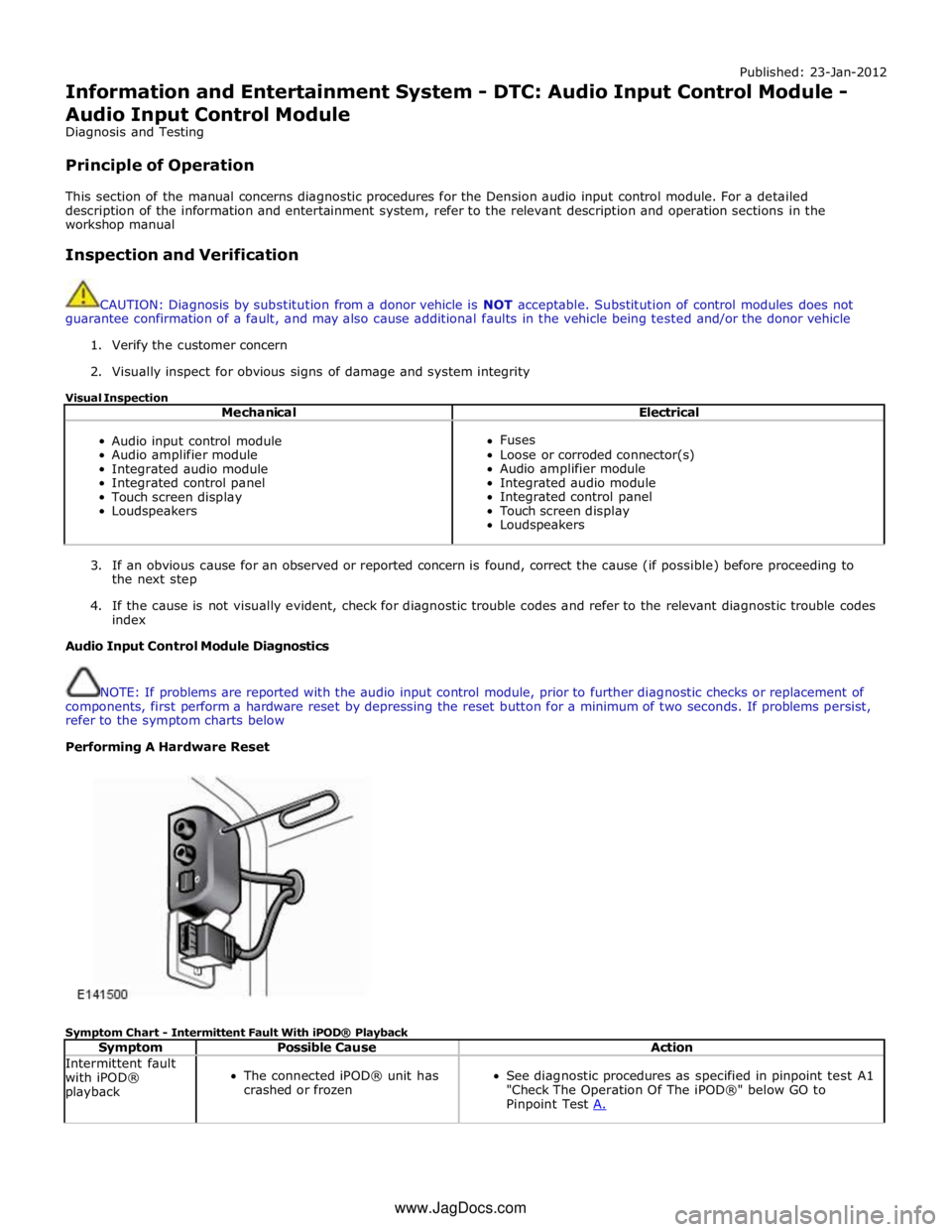
Audio Input Control Module Diagnostics
NOTE: If problems are reported with the audio input control module, prior to further diagnostic checks or replacement of
components, first perform a hardware reset by depressing the reset button for a minimum of two seconds. If problems persist,
refer to the symptom charts below
Performing A Hardware Reset
Symptom Chart - Intermittent Fault With iPOD® Playback
Symptom Possible Cause Action Intermittent fault
with iPOD®
playback
The connected iPOD® unit has
crashed or frozen
See diagnostic procedures as specified in pinpoint test A1
"Check The Operation Of The iPOD®" below GO to
Pinpoint Test A. www.JagDocs.com
Page 2017 of 3039
Is the USB extension cable securely pushed into the USB connection port on the audio input control module
Yes
Replace the USB extension cable
No
Secure connections and retest B4: CHECK THE CAPACITY OF THE MEMORY STICK/STORAGE DEVICE
NOTE: The higher the capacity of the memory stick is the longer it takes to register with the audio input control module
and power up. The maximum permitted capacity is 8 Gigabytes 1 Check the storage capacity of the memory stick/storage device does not exceed 8 Gigabytes Is the storage capacity of the memory stick/storage device 8 Gigabytes or less?
Yes
High capacity devices may require longer to register and should be allowed up to two minutes to power up
following connection to the USB port. If memory stick fails to power up after two minutes, suspect a
faulty memory stick GO to B2. or USB extension cable GO to B3. No
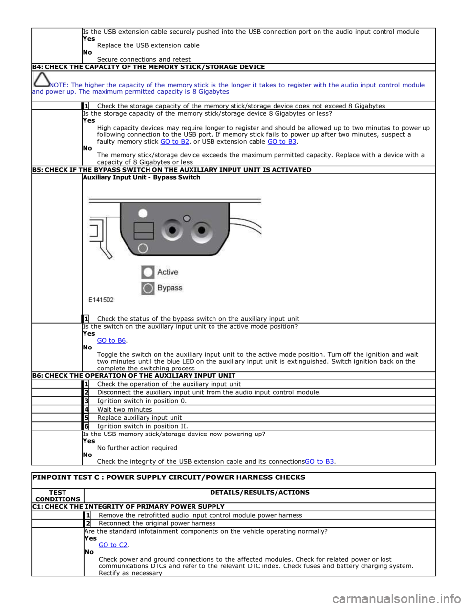
The memory stick/storage device exceeds the maximum permitted capacity. Replace with a device with a capacity of 8 Gigabytes or less B5: CHECK IF THE BYPASS SWITCH ON THE AUXILIARY INPUT UNIT IS ACTIVATED Auxiliary Input Unit - Bypass Switch
1 Check the status of the bypass switch on the auxiliary input unit Is the switch on the auxiliary input unit to the active mode position?
Yes
GO to B6. No
Toggle the switch on the auxiliary input unit to the active mode position. Turn off the ignition and wait
two minutes until the blue LED on the auxiliary input unit is extinguished. Switch ignition back on the complete the switching process B6: CHECK THE OPERATION OF THE AUXILIARY INPUT UNIT 1 Check the operation of the auxiliary input unit 2 Disconnect the auxiliary input unit from the audio input control module. 3 Ignition switch in position 0. 4 Wait two minutes 5 Replace auxiliary input unit 6 Ignition switch in position II. Is the USB memory stick/storage device now powering up?
Yes
No further action required
No
Check the integrity of the USB extension cable and its connectionsGO to B3.
PINPOINT TEST C : POWER SUPPLY CIRCUIT/POWER HARNESS CHECKS TEST
CONDITIONS DETAILS/RESULTS/ACTIONS C1: CHECK THE INTEGRITY OF PRIMARY POWER SUPPLY 1 Remove the retrofitted audio input control module power harness 2 Reconnect the original power harness Are the standard infotainment components on the vehicle operating normally?
Yes
GO to C2. No
Check power and ground connections to the affected modules. Check for related power or lost
communications DTCs and refer to the relevant DTC index. Check fuses and battery charging system. Rectify as necessary