2010 JAGUAR XFR Security
[x] Cancel search: SecurityPage 1889 of 3039
Battery, Mounting and Cables - Battery
Diagnosis and Testing
Principles of Operation Published: 10-Mar-2014
For a detailed description of the battery system and operation, refer to the relevant Description and Operation section of the
workshop manual. REFER to: Battery and Cables (414-01 Battery, Mounting and Cables, Description and Operation).
Inspection and Verification
CAUTION: Diagnosis by substitution from a donor vehicle is NOT acceptable. Substitution of control modules does not
guarantee confirmation of a fault and may also cause additional faults in the vehicle being checked and/or the donor vehicle.
NOTES:
Generic scan tools may not read the codes listed, or may read only five digit codes. Match the five digits from the scan
tool to the first five digits of the seven digit code listed to identify the fault (the last two digits give additional information
read by the manufacturer-approved diagnostic system).
When performing electrical voltage or resistance tests, always use a digital multimeter (DMM) accurate to three decimal
places, and with an up-to-date calibration certificate. When testing resistance, always take the resistance of the DMM leads
into account.
Check and rectify basic faults before beginning diagnostic routines involving pinpoint tests.
If DTCs are recorded and, after performing the pinpoint tests, a fault is not present, an intermittent concern may be the
cause. Always check for loose connections and corroded terminals.
1. Verify the customer concern.
2. Visually inspect for obvious signs of mechanical or electrical damage.
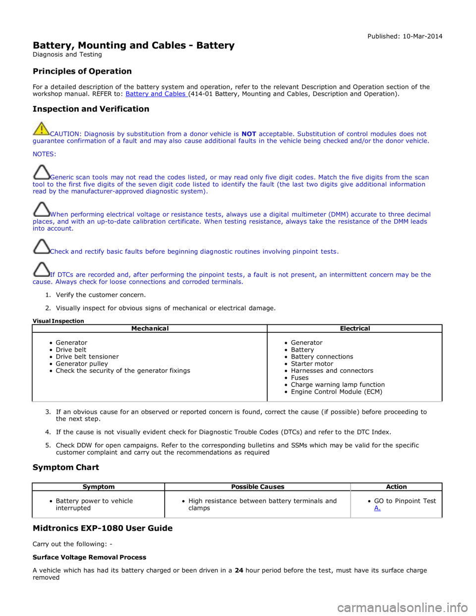
Visual Inspection
Mechanical Electrical
Generator
Drive belt
Drive belt tensioner
Generator pulley
Check the security of the generator fixings
Generator
Battery
Battery connections
Starter motor
Harnesses and connectors
Fuses
Charge warning lamp function
Engine Control Module (ECM)
3. If an obvious cause for an observed or reported concern is found, correct the cause (if possible) before proceeding to
the next step.
4. If the cause is not visually evident check for Diagnostic Trouble Codes (DTCs) and refer to the DTC Index.
5. Check DDW for open campaigns. Refer to the corresponding bulletins and SSMs which may be valid for the specific
customer complaint and carry out the recommendations as required
Symptom Chart
Symptom Possible Causes Action
Battery power to vehicle
interrupted
High resistance between battery terminals and
clamps
GO to Pinpoint Test
A. Midtronics EXP-1080 User Guide
Carry out the following: -
Surface Voltage Removal Process
A vehicle which has had its battery charged or been driven in a 24 hour period before the test, must have its surface charge
removed
Page 1932 of 3039
Published: 11-Jul-2014
Information and Entertainment System - General Information - Information
and Entertainment System
Diagnosis and Testing
Principle of Operation
For a detailed description of the Information and Entertainment System, refer to the relevant Description and Operation
sections in the workshop manual. REFER to: (415-01A Information and Entertainment System)
Audio System (Description and Operation), Audio System (Description and Operation), Audio System (Description and Operation).
Inspection and Verification
CAUTION: Diagnosis by substitution from a donor vehicle is NOT acceptable. Substitution of control modules does not
guarantee confirmation of a fault, and may also cause additional faults in the vehicle being tested and/or the donor vehicle.
1. Verify the customer concern.
2. Visually inspect for obvious signs of damage and system integrity.
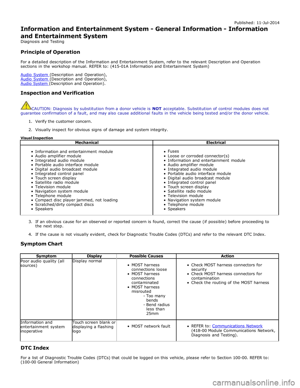
Visual Inspection
Mechanical Electrical
Information and entertainment module
Audio amplifier module
Integrated audio module
Portable audio interface module
Digital audio broadcast module
Integrated control panel
Touch screen display
Satellite radio module
Television module
Navigation system module
Telephone module
Compact disc player jammed, not loading
Scratched/dirty compact discs
Speakers
Fuses
Loose or corroded connector(s)
Information and entertainment module
Audio amplifier module
Integrated audio module
Portable audio interface module
Digital audio broadcast module
Integrated control panel
Touch screen display
Satellite radio module
Television module
Navigation system module
Telephone module
Speakers
3. If an obvious cause for an observed or reported concern is found, correct the cause (if possible) before proceeding to
the next step.
4. If the cause is not visually evident, check for Diagnostic Trouble Codes (DTCs) and refer to the relevant DTC Index.
Symptom Chart
Symptom Display Possible Causes Action Poor audio quality (all
sources) Display normal
MOST harness
connections loose
MOST harness
connections
contaminated
MOST harness
misrouted
- Too many
bends
- Bend radius
less than
25mm
Check MOST harness connectors for
security
Check MOST harness connectors for
contamination
Check the routing of the MOST harness Information and
entertainment system
inoperative Touch screen blank or
displaying a flashing
logo
MOST network fault
REFER to: Communications Network (418-00 Module Communications Network,
Diagnosis and Testing).
DTC Index
For a list of Diagnostic Trouble Codes (DTCs) that could be logged on this vehicle, please refer to Section 100-00. REFER to:
(100-00 General Information)
Page 1949 of 3039
systems.
A typical example of information transfer is vehicle speed information from the ABS (anti-lock brake system) module used to
control the automatic volume control function. The vehicle speed information from the ABS module is sent on the high speed
CAN network and collected by the instrument panel gateway. The signal is passed to the medium speed CAN network and onto the ICM gateway. The ICM calculates the volume adjustment required. The corrected audio volume level signal is sent on the
MOST network to the IAM or Power amplifier (dependant on vehicle equipment level) for output to the speaker system.
AUDIO SYSTEM USER CONTROLS
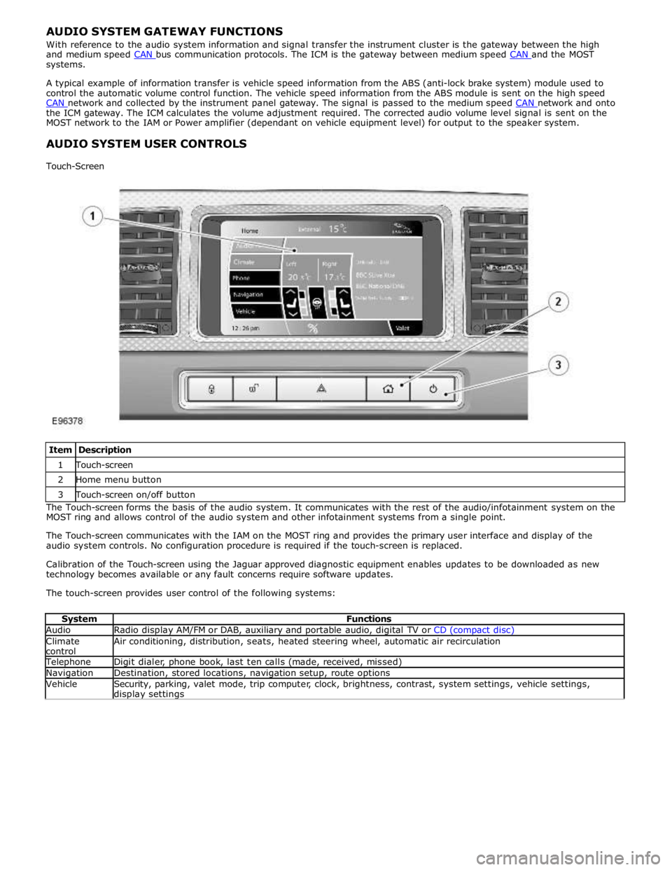
Touch-Screen
Item Description 1 Touch-screen 2 Home menu button 3 Touch-screen on/off button The Touch-screen forms the basis of the audio system. It communicates with the rest of the audio/infotainment system on the
MOST ring and allows control of the audio system and other infotainment systems from a single point.
The Touch-screen communicates with the IAM on the MOST ring and provides the primary user interface and display of the
audio system controls. No configuration procedure is required if the touch-screen is replaced.
Calibration of the Touch-screen using the Jaguar approved diagnostic equipment enables updates to be downloaded as new
technology becomes available or any fault concerns require software updates.
The touch-screen provides user control of the following systems:
System Functions Audio Radio display AM/FM or DAB, auxiliary and portable audio, digital TV or CD (compact disc) Climate
control Air conditioning, distribution, seats, heated steering wheel, automatic air recirculation Telephone Digit dialer, phone book, last ten calls (made, received, missed) Navigation Destination, stored locations, navigation setup, route options Vehicle
Security, parking, valet mode, trip computer, clock, brightness, contrast, system settings, vehicle settings, display settings
Page 1981 of 3039
Navigation Destination, stored locations, navigation setup, route options Vehicle
Security, parking, valet mode, trip computer, clock, brightness, contrast, system settings, vehicle settings, display settings The screen is a touch sensitive 7 inch LCD (liquid crystal display) VGA screen containing 800 x 480 pixels in a 15:9 format. The
screen processes its own video for system operation but receives the navigation graphics from the navigation computer.
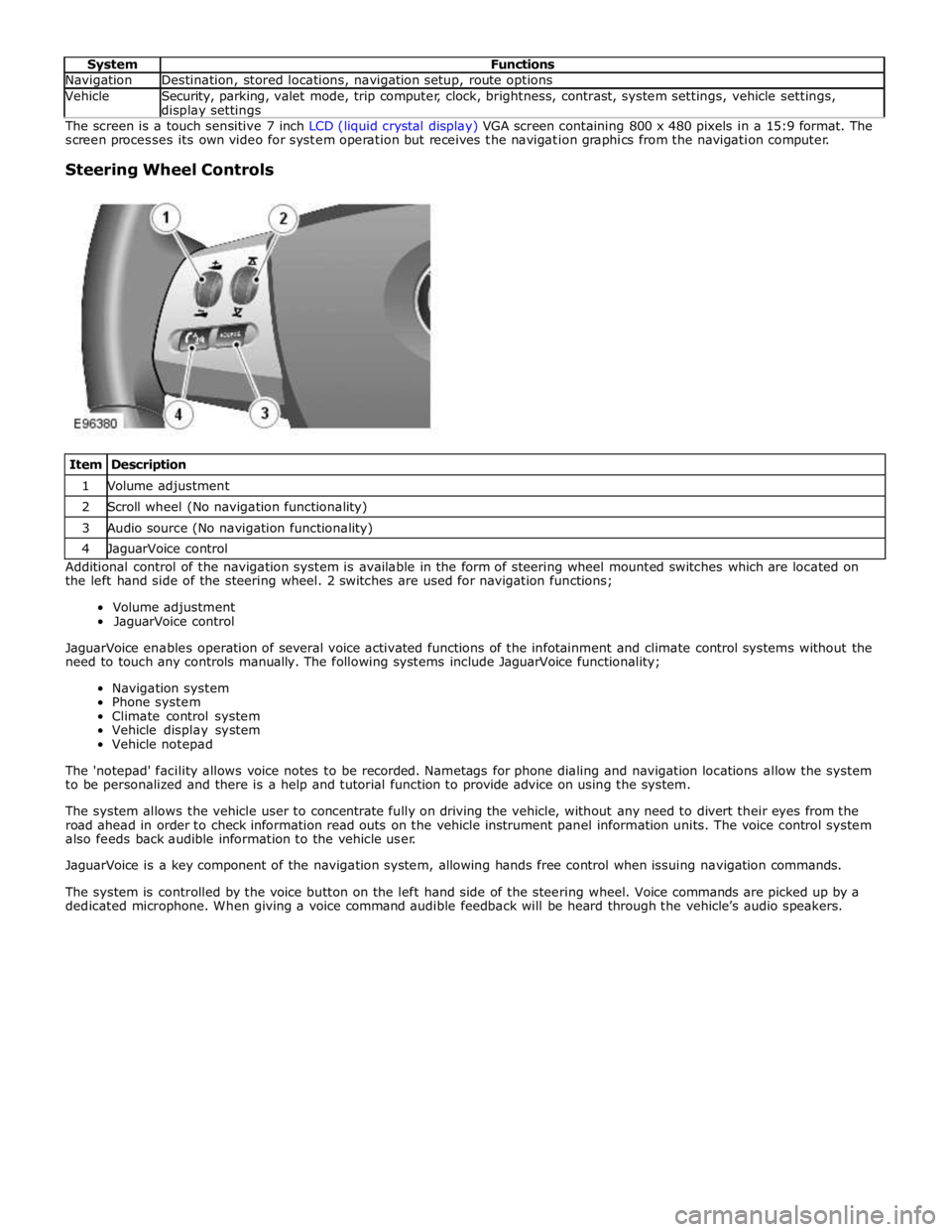
Steering Wheel Controls
Item Description 1 Volume adjustment 2 Scroll wheel (No navigation functionality) 3 Audio source (No navigation functionality) 4 JaguarVoice control Additional control of the navigation system is available in the form of steering wheel mounted switches which are located on
the left hand side of the steering wheel. 2 switches are used for navigation functions;
Volume adjustment
JaguarVoice control
JaguarVoice enables operation of several voice activated functions of the infotainment and climate control systems without the
need to touch any controls manually. The following systems include JaguarVoice functionality;
Navigation system
Phone system
Climate control system
Vehicle display system
Vehicle notepad
The 'notepad' facility allows voice notes to be recorded. Nametags for phone dialing and navigation locations allow the system
to be personalized and there is a help and tutorial function to provide advice on using the system.
The system allows the vehicle user to concentrate fully on driving the vehicle, without any need to divert their eyes from the
road ahead in order to check information read outs on the vehicle instrument panel information units. The voice control system
also feeds back audible information to the vehicle user.
JaguarVoice is a key component of the navigation system, allowing hands free control when issuing navigation commands.
The system is controlled by the voice button on the left hand side of the steering wheel. Voice commands are picked up by a
dedicated microphone. When giving a voice command audible feedback will be heard through the vehicle’s audio speakers.
Page 2060 of 3039
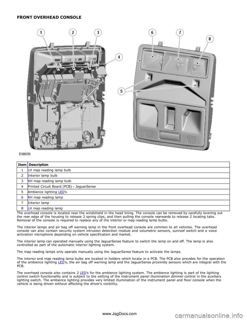
1 LH map reading lamp bulb 2 Interior lamp bulb 3 RH map reading lamp bulb 4 Printed Circuit Board (PCB) - JaguarSense 5 Ambience lighting LED's 6 RH map reading lamp 7 Interior lamp 8 LH map reading lamp The overhead console is located near the windshield in the head lining. The console can be removed by carefully levering out
the rear edge of the housing to release 2 spring clips, and then pulling the console rearwards to release 2 locating tabs.
Removal of the console is required to replace any of the interior or map reading lamp bulbs.
The interior lamps and air bag off warning lamp in the front overhead console are common to all vehicles. The overhead
console can also contain security system intrusion detection module and volumetric sensors, sunroof switch and a voice
activation microphone depending on vehicle specification and market.
The interior lamp can operated manually using the JaguarSense feature to switch the lamp on and off. The lamp is also
controlled as part of the automatic interior lighting system.
The map reading lamps only operate manually using the JaguarSense feature to activate the lamps.
The interior and map reading lamp bulbs are located in holders which locate in a PCB. The PCB also provides for the operation
of the ambience lighting LED's, the air bag off warning lamp and the JaguarSense proximity sensors which are integral with the PCB.
The overhead console also contains 2 LED's for the ambience lighting system. The ambience lighting is part of the lighting control switch functionality and is subject to the setting of the instrument panel illumination dimmer control in the auxiliary
lighting switch. The ambience lighting provides very limited illumination of the instrument panel and floor console when the
vehicle is being driven without affecting the driver's visibility. www.JagDocs.com
Page 2088 of 3039

DTC Description Possible Cause Action B110011
O2 sensor heater
relay
FPDB O2 sensor heater relay
control circuit - short to ground Carry out any pinpoint tests associated with this DTC
using the manufacturer approved diagnostic system.
Refer to the electrical circuit diagrams and check FPDB O2
sensor heater relay control circuit for short to ground B113D12
Sunroof Global
Open/Close Control
Roof opening panel global
open/close control circuit -
short to power Carry out any pinpoint tests associated with this DTC
using the manufacturer approved diagnostic system.
Refer to the electrical circuit diagrams and check roof
opening panel global open/close control circuit for short
to power B113D14
Sunroof Global
Open/Close Control
Roof opening panel global
open/close control circuit -
short to ground, open circuit Refer to the electrical circuit diagrams and check roof
opening panel global open/close control circuit for short
to ground, open circuit B114011
Engine Crank
Authorisation
Engine crank authorisation
signal circuit - short to ground Carry out any pinpoint tests associated with this DTC
using the manufacturer approved diagnostic system.
Refer to the electrical circuit diagrams and check engine
crank authorisation signal circuit for short to ground B114211 Ignition Status 1
Ignition supply 1 circuits -
short to ground Carry out any pinpoint tests associated with this DTC
using the manufacturer approved diagnostic system.
Refer to the electrical circuit diagrams and check all ignition supply 1 circuits for short to ground B114311 Ignition Status 2
Ignition supply 2 circuits -
short to ground Carry out any pinpoint tests associated with this DTC
using the manufacturer approved diagnostic system.
Refer to the electrical circuit diagrams and check all ignition supply 2 circuits for short to ground B114411
Heated Steering
Wheel Supply
Heated steering wheel supply
circuit - short to ground Carry out any pinpoint tests associated with this DTC
using the manufacturer approved diagnostic system.
Refer to the electrical circuit diagrams and check heated steering wheel supply circuit for short to ground B114511
Glovebox Locking
Motor
Glovebox latch locking motor
circuit - short to ground Carry out any pinpoint tests associated with this DTC
using the manufacturer approved diagnostic system.
Refer to the electrical circuit diagrams and check glovebox latch locking motor circuit for short to ground B114512
Glovebox Locking
Motor
Glovebox latch locking motor
control circuit - short to power Refer to the electrical circuit diagrams and check
glovebox latch locking motor control circuit for short to
power B114513
Glovebox Locking
Motor
Glovebox latch locking motor
control circuit - open circuit Refer to the electrical circuit diagrams and check
glovebox latch locking motor control circuit for open
circuit B114612
Passive sounder
Supply
Security passive sounder
control circuit - short to power Refer to the electrical circuit diagrams and check security
passive sounder control circuit for short to power B114614
Passive sounder
Supply
Security passive sounder
control circuit - short to ground,
open circuit Refer to the electrical circuit diagrams and check security
passive sounder control circuit for short to ground, open
circuit B115811
Front Passenger
Seat Heater Sensor
Front passenger seat heater
sensor circuit - short to ground Carry out any pinpoint tests associated with this DTC
using the manufacturer approved diagnostic system.
Refer to the electrical circuit diagrams and check front passenger seat heater sensor circuit for short to ground B115813
Front Passenger
Seat Heater Sensor
Front passenger seat heater
sensor circuit - open circuit Carry out any pinpoint tests associated with this DTC
using the manufacturer approved diagnostic system.
Refer to the electrical circuit diagrams and check front passenger seat heater sensor circuit for open circuit B115911
Driver Seat Heater
Sensor
Driver seat heater sensor
circuit - short to ground Carry out any pinpoint tests associated with this DTC
using the manufacturer approved diagnostic system.
Refer to the electrical circuit diagrams and check driver
seat heater sensor circuit for short to ground B115913
Driver Seat Heater
Sensor
Driver seat heater sensor
circuit - open circuit Carry out any pinpoint tests associated with this DTC
using the manufacturer approved diagnostic system.
Refer to the electrical circuit diagrams and check driver
seat heater sensor circuit for open circuit B115A11
Front Passenger
Seat Heater
Front passenger seat heater
supply circuit - short to ground Carry out any pinpoint tests associated with this DTC
using the manufacturer approved diagnostic system.
Refer to the electrical circuit diagrams and check front passenger seat heater supply circuit for short to ground B115A15
Front Passenger
Seat Heater
Front passenger seat heater
supply circuit - short to power,
open circuit Carry out any pinpoint tests associated with this DTC
using the manufacturer approved diagnostic system.
Refer to the electrical circuit diagrams and check front
passenger seat heater supply circuit for short to power, open circuit
Page 2091 of 3039

DTC Description Possible Cause Action B1D2711
Heater Coolant
Pump
Heater coolant pump control
circuit - short to ground Carry out any pinpoint tests associated with this DTC
using the manufacturer approved diagnostic system.
Refer to the electrical circuit diagrams and check heater
coolant pump control circuit for short to ground B1D2713
Heater Coolant
Pump
Heater coolant pump control
circuit - open circuit Carry out any pinpoint tests associated with this DTC
using the manufacturer approved diagnostic system.
Refer to the electrical circuit diagrams and check heater
coolant pump control circuit for open circuit B1D9796 Tilt Sensor
Component internal failure Suspect the battery backed sounder, check and install a
new battery backed sounder as required P057112
Brake Switch A
Circuit
Footbrake switch circuit - short
to power Refer to the electrical circuit diagrams and check
footbrake switch circuit for short to power P080111
Reverse Inhibit
Control Circuit
Electrochromic rear view mirror,
reverse inhibit circuit - short to
ground Carry out any pinpoint tests associated with this DTC
using the manufacturer approved diagnostic system.
Refer to the electrical circuit diagrams and check
electrochromic rear view mirror, reverse inhibit circuit for
short to ground P080112
Reverse Inhibit
Control Circuit
Electrochromic rear view mirror,
reverse inhibit circuit - short to
power Refer to the electrical circuit diagrams and check
electrochromic rear view mirror, reverse inhibit circuit for
short to power P080113
Reverse Inhibit
Control Circuit
Electrochromic rear view mirror,
reverse inhibit circuit - open
circuit Refer to the electrical circuit diagrams and check
electrochromic rear view mirror, reverse inhibit circuit for
open circuit P085013
Park/Neutral Switch
Input Circuit
Park/Neutral signal circuit -
open circuit Refer to the electrical circuit diagrams and check
Park/Neutral signal circuit for open circuit P162413 Anti-theft System
RJB anti-theft signal circuit -
open circuit Refer to the electrical circuit diagrams and check RJB
anti-theft signal circuit for open circuit P254F13
Engine Hood Switch
Circuit/Open
Hood ajar switch signal circuit -
open circuit Refer to the electrical circuit diagrams and check hood
ajar switch signal circuit for open circuit U001988
Low Speed CAN
Communication Bus
Bus OFF Carry out any pinpoint tests associated with this DTC
using the manufacturer approved diagnostic system. U014200
Lost
Communication
With Body Control
Module "B"
No sub type information Carry out any pinpoint tests associated with this DTC
using the manufacturer approved diagnostic system. U015500
Lost
Communication
With Instrument
Panel Cluster (IPC)
Control Module
No sub type information Carry out any pinpoint tests associated with this DTC
using the manufacturer approved diagnostic system. U015600
Lost
Communication
With Information
Center "A"
No sub type information Carry out any pinpoint tests associated with this DTC
using the manufacturer approved diagnostic system. U016400
Lost
Communication
With HVAC Control
Module
No sub type information Carry out any pinpoint tests associated with this DTC
using the manufacturer approved diagnostic system. U016800
Lost
Communication
With Vehicle
Security Control
Module
No sub type information Check power and ground supplies to vehicle security
module U019900
Lost
Communication
With "Door Control
Module A"
No sub type information Carry out any pinpoint tests associated with this DTC
using the manufacturer approved diagnostic system. U020000
Lost
Communication
With "Door Control
Module B"
No sub type information Carry out any pinpoint tests associated with this DTC
using the manufacturer approved diagnostic system.
Page 2092 of 3039
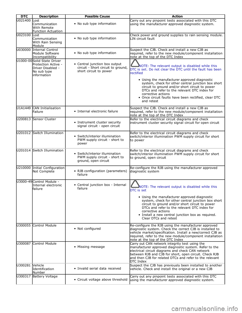
DTC Description Possible Cause Action U021400
Lost
Communication
With Remote
Function Actuation
No sub type information Carry out any pinpoint tests associated with this DTC
using the manufacturer approved diagnostic system. U023100
Lost
Communication
With Rain Sensing
Module
No sub type information Check power and ground supplies to rain sensing module.
LIN circuit fault U030000
Internal Control
Module Software Incompatibility
No sub type information Suspect the CJB. Check and install a new CJB as
required, refer to the new module/component installation
note at the top of the DTC Index U1000-00
Solid State Driver
Protection Active -
Driver Disabled -
No sub type
information
Central junction box output
circuit - Short circuit to ground,
short circuit to power
NOTE: The relevant output is disabled while this
DTC is set. Do not clear the DTC until the fault has been
rectified
Using the manufacturer approved diagnostic
system, check for other central junction box short
circuit to ground and/or short circuit to power
DTCs and refer to the relevant DTC index for
corrective actions
Once circuit faults have been rectified, clear DTC
and retest U1A1449
CAN Initialisation
Failure
Internal electronic failure Suspect the CJB. Check and install a new CJB as
required, refer to the new module/component installation
note at the top of the DTC Index U200813 Sensor Cluster
Instrument cluster security
signal circuit - open circuit Refer to the electrical circuit diagrams and check
instrument cluster security signal circuit for open circuit U201012 Switch Illumination
Switch/interior illumination
PWM supply circuit - short to
power Refer to the electrical circuit diagrams and check
switch/interior illumination PWM supply circuit for short
to power U201014 Switch Illumination
Switch/interior illumination
PWM supply circuit - short to
ground, open circuit Refer to the electrical circuit diagrams and check
switch/interior illumination PWM supply circuit for short
to ground, open circuit U210000
Initial Configuration
Not Complete
RJB configuration (parameters)
failure Re-configure the RJB using the manufacturer approved
diagnostic system U3000-49
Control Module -
Internal electronic
failure
Central junction box - Internal
failure
NOTE: The relevant output is disabled while this
DTC is set
Using the manufacturer approved diagnostic
system, check for other central junction box short
circuit to ground and/or short circuit to power
DTCs and refer to the relevant DTC index for
corrective actions
Install a new central junction box as required.
Clear DTCs and retest U300055 Control Module
Not configured Re-configure the RJB using the manufacturer approved
diagnostic system. Check the correct CJB is installed to
vehicle market/specification. Install a new/correct CJB as
required, refer to the new module/component installation
note at the top of the DTC Index U300087 Control Module
Missing message Carry out CAN network integrity test using the
manufacturer approved diagnostic system. Refer to the
electrical circuit diagrams and check CAN network
between RJB and CJB for short, open circuit. Check RJB
and then CJB for related DTCs and refer to the relevant
DTC Index U300281
Vehicle
Identification
Number
Invalid serial data received Suspect the CJB has previously been installed to another
vehicle. Check and install the original or a new CJB U300317 Battery Voltage
Circuit voltage above threshold Carry out any pinpoint tests associated with this DTC
using the manufacturer approved diagnostic system.