2010 JAGUAR XFR Electrical
[x] Cancel search: ElectricalPage 1649 of 3039

DTC Description Possible Causes Action U0401-00
Invalid Data Received
From ECM/PCM A - No
sub type information
ECM did not respond
properly to speed control
cancel or auto brake
cancel request
Check ECM for related DTCs and refer to relevant
DTC Index U0401-67
Invalid Data Received
From ECM/PCM A -
Signal incorrect after
event
ECM did not respond
properly to speed control
resume request
Check ECM for related DTCs and refer to relevant
DTC Index U0401-81
Invalid Data Received
From ECM/PCM A -
Invalid serial data
received
Invalid data received
from engine control
module
Bus signal/message
failure
Speed control inhibited
by ECM
Check the Engine Control Module for related DTCs
and refer to relevant DTC Index. If U040181 is
logged as historic but no other DTCs have logged in
the engine control module at the same time and
distance, it may be caused by cranking with low
voltage conditions. Check battery and charging
system according to instructions in the battery care
manual. Install the latest Engine Control Module
software using the manufacturer approved diagnostic
system, contact Dealer Technical Support before
replacing components U0415-53
Invalid Data Received
From Anti-Lock Braking
System (ABS) Control
Module - De-activated
Event information
Deactivated
Check the Anti-Lock Braking System Module for
related DTCs and refer to the relevant DTC index U0415-81
Invalid Data Received
From Anti-lock Brake
System (ABS) Control
Module - Invalid serial
data received
Stability assist fault
Check ABS module for related DTCs and refer to
relevant DTC Index U0417-67
Invalid Data Received
From Park Brake
Control Module - Signal
incorrect after event
Parking brake module did
not respond properly to
apply request
Check parking brake module for related DTCs and
refer to relevant DTC Index U0417-81
Invalid Data Received
From Park Brake
Control Module -
Invalid serial data
received
Speed control inhibited
by parking brake module
Check parking brake module for related DTCs and
refer to relevant DTC Index U0418-68
Invalid Data Received
From Brake System
Control Module - Event
information
Event information
Check the Anti-Lock Braking System Module for
related DTCs and refer to the relevant DTC index U0421-81
Invalid Data Received
From Suspension
Control Module 'A' -
Invalid serial data
received
Invalid serial data
received
Check the Suspension Control Module for related
DTCs and refer to the relevant DTC index U0423-81
Invalid Data Received
From Instrument Panel
Control Module -
Invalid serial data
received
Speed control inhibited
by instrument cluster
Check instrument cluster, CJB and RJB for related
DTCs and refer to relevant DTC Index U1A00-88
Private Communication
Network - Bus off
Bus off
The module setting this code has disabled CAN
transmission. Check for other bus off codes. Check
the module and circuits. Refer to the electrical circuit
diagrams. Clear all DTCs and road test the vehicle. If
the concern reoccurs contact Dealer Technical
Support for further advice. Under no circumstance
should any parts be replaced to overcome this issue U1A14-49
CAN Initialisation
Failure - Internal
electronic failure
Internal electronic failure
Suspect the speed control module. Check and install
a new module as required, refer to the new
module/component installation note at the top of
the DTC Index U2101-00
Control Module
Configuration
Incompatible - No sub
type information
Data sent from RJB is
invalid
Check/amend Car Configuration File using the
manufacturer approved diagnostic system, clear DTC
and re-test. If DTC remains, re-configure RJB using
manufacturer approved diagnostic system, clear DTC
and re-test. If DTC remains check RJB for DTCs and
Page 1650 of 3039
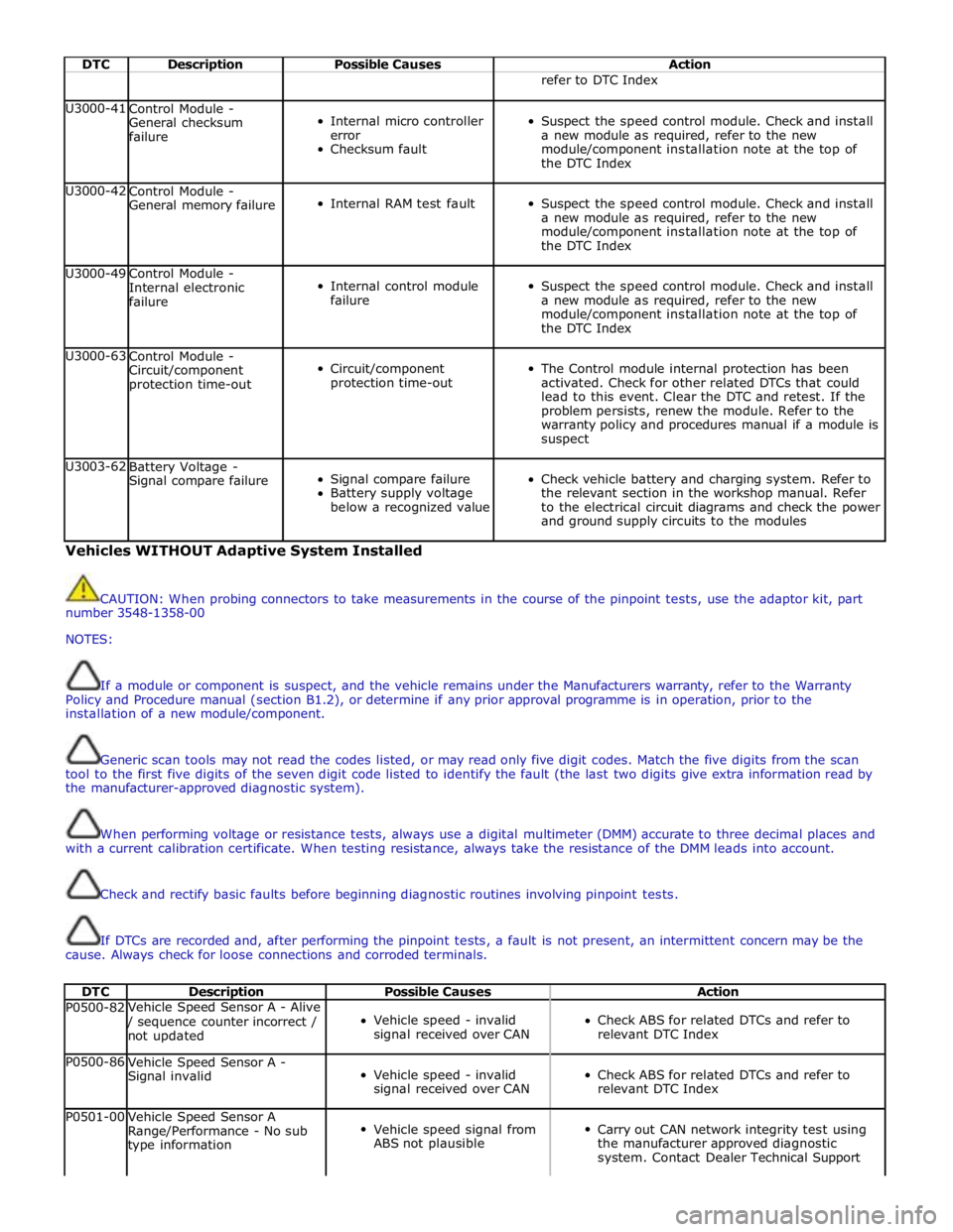
DTC Description Possible Causes Action refer to DTC Index U3000-41
Control Module -
General checksum
failure
Internal micro controller
error
Checksum fault
Suspect the speed control module. Check and install
a new module as required, refer to the new
module/component installation note at the top of
the DTC Index U3000-42
Control Module -
General memory failure
Internal RAM test fault
Suspect the speed control module. Check and install
a new module as required, refer to the new
module/component installation note at the top of
the DTC Index U3000-49
Control Module -
Internal electronic
failure
Internal control module
failure
Suspect the speed control module. Check and install
a new module as required, refer to the new
module/component installation note at the top of
the DTC Index U3000-63
Control Module -
Circuit/component
protection time-out
Circuit/component
protection time-out
The Control module internal protection has been
activated. Check for other related DTCs that could
lead to this event. Clear the DTC and retest. If the
problem persists, renew the module. Refer to the
warranty policy and procedures manual if a module is
suspect U3003-62
Battery Voltage -
Signal compare failure
Signal compare failure
Battery supply voltage
below a recognized value
Check vehicle battery and charging system. Refer to
the relevant section in the workshop manual. Refer
to the electrical circuit diagrams and check the power
and ground supply circuits to the modules Vehicles WITHOUT Adaptive System Installed
CAUTION: When probing connectors to take measurements in the course of the pinpoint tests, use the adaptor kit, part
number 3548-1358-00
NOTES:
If a module or component is suspect, and the vehicle remains under the Manufacturers warranty, refer to the Warranty
Policy and Procedure manual (section B1.2), or determine if any prior approval programme is in operation, prior to the
installation of a new module/component.
Generic scan tools may not read the codes listed, or may read only five digit codes. Match the five digits from the scan
tool to the first five digits of the seven digit code listed to identify the fault (the last two digits give extra information read by
the manufacturer-approved diagnostic system).
When performing voltage or resistance tests, always use a digital multimeter (DMM) accurate to three decimal places and
with a current calibration certificate. When testing resistance, always take the resistance of the DMM leads into account.
Check and rectify basic faults before beginning diagnostic routines involving pinpoint tests.
If DTCs are recorded and, after performing the pinpoint tests, a fault is not present, an intermittent concern may be the
cause. Always check for loose connections and corroded terminals.
DTC Description Possible Causes Action P0500-82 Vehicle Speed Sensor A - Alive / sequence counter incorrect /
not updated
Vehicle speed - invalid
signal received over CAN
Check ABS for related DTCs and refer to
relevant DTC Index P0500-86
Vehicle Speed Sensor A -
Signal invalid
Vehicle speed - invalid
signal received over CAN
Check ABS for related DTCs and refer to
relevant DTC Index P0501-00
Vehicle Speed Sensor A
Range/Performance - No sub
type information
Vehicle speed signal from
ABS not plausible
Carry out CAN network integrity test using
the manufacturer approved diagnostic
system. Contact Dealer Technical Support
Page 1651 of 3039

DTC Description Possible Causes Action for further assistance P0501-62
Vehicle Speed Sensor A
Range/Performance - Signal
compare failure
Vehicle speed - range
performance
Check ABS/TCM for related DTCs and refer
to relevant DTC Index P0504-00 Brake Switch A / B Correlation
- No sub type information
The brake pressure reading
does not agree with the
brake light switch value
Carry out any pinpoint tests associated with
this DTC using the manufacturer approved
diagnostic system. Refer to the electrical
circuit diagrams and check brake switch
circuits for short, open circuit, high
resistance P0504-01 Brake Switch A / B Correlation
- General electrical failure
Brake switch high fault:
- Brake lights stuck
on
- Gearshift interlock
inoperative
- Speed control
inoperative
Brake switch low fault:
- Brake lights
inoperative
- Gearshift stuck in
Park
- Reduced engine
braking
Carry out any pinpoint tests associated with
this DTC using the manufacturer approved
diagnostic system. Refer to the electrical
circuit diagrams and check brake switch
circuits for short, open circuit, high
resistance P0566-00
Cruise Control OFF Signal - No
sub type information
Speed control Cancel
switch 2 stuck closed
Refer to the electrical circuit diagrams and
check speed control switch circuits for short,
open circuit. Check for stuck switch. Check
and install a new speed control switch as
required P0567-00
Cruise Control DECREASE
DISTANCE Signal - No sub
type information
Speed control Resume
switch 7 stuck closed
Refer to the electrical circuit diagrams and
check speed control switch circuits for short,
open circuit. Check for stuck switch. Check
and install a new speed control switch as
required P0568-00
Cruise Control INCREASE
DISTANCE Signal - No sub
type information
Speed control Accel Set
Plus Switch 6 stuck closed
Check and install a new speed control
switch as required P0569-00
Cruise Control COAST Signal -
No sub type information
Speed control Coast Set
Minus switch 3 stuck
closed
Refer to the electrical circuit diagrams and
check speed control switch circuits for short,
open circuit. Check for stuck switch. Check
and install a new speed control switch as
required P056A-00
Cruise Control INCREASE
DISTANCE Signal - No sub
type information
Speed control Headway
Plus switch 4 stuck closed
Refer to the electrical circuit diagrams and
check speed control switch circuits for short,
open circuit. Check for stuck switch. Check
and install a new speed control switch as
required P056B-00
Cruise Control DECREASE
DISTANCE Signal - No sub
type information
Speed control Headway
Minus switch 5 stuck
closed
Refer to the electrical circuit diagrams and
check speed control switch circuits for short,
open circuit. Check for stuck switch. Check
and install a new speed control switch as
required P0571-62
Brake Switch A Circuit - Signal
compare failure
Plausibility error
Refer to the electrical circuit diagrams and
check brake light switch signal circuits for
short, open circuit. Check and install a new
brake light switch as required P0575-01
Cruise Control Input Circuit -
General electrical failure
General electrical failure
Check speed control system for related
DTCs and refer to relevant DTC Index. Carry
out CAN network integrity tests using the
Page 1652 of 3039

DTC Description Possible Causes Action manufacturer approved diagnostic system P0576-16
Cruise Control Input Circuit
Low - Circuit voltage below
threshold
Circuit voltage below
threshold
Check speed control system for related
DTCs and refer to relevant DTC Index. Carry
out CAN network integrity tests using the
manufacturer approved diagnostic system P0577-17
Cruise Control Input Circuit
High - Circuit voltage above
threshold
Circuit voltage above
threshold
Check speed control system for related
DTCs and refer to relevant DTC Index. Carry
out CAN network integrity tests using the
manufacturer approved diagnostic system P0578-00
Cruise Control Multi-Function
Input A Circuit Stuck - No sub
type information
One of speed control
switches stuck
Check for stuck speed control switch, install
a new switch pack as required P0578-1C
Cruise Control Multi-Function
Input A Circuit Stuck - Circuit
voltage out of range
Circuit voltage out of range
Refer to the electrical circuit diagrams and
check speed control switch circuits for short,
open circuit. Check for stuck switch. Check
and install a new speed control switch as
required P0579-1C
Cruise Control Multi-Function
Input A Circuit
Range/Performance - Circuit voltage out of range
Speed control switch pack
internal failure
Check and install a new speed control
switch pack as required P0579-29
Cruise Control Multi-Function
Input A Circuit
Range/Performance - Signal
invalid
Signal invalid
Refer to the electrical circuit diagrams and
check speed control switch circuits for short,
open circuit. Check for stuck switch. Check
and install a new speed control switch as
required P0590-00
Cruise Control Multi-Function
Input B Circuit Stuck - No sub
type information
Active speed limiter fault
Check for active speed limiter fault, install a
new transmission shift module as required
Page 1664 of 3039
Published: 11-Jul-2014
Climate Control System - General Information - Climate Control System
Diagnosis and Testing
Principles of Operation
For a detailed description of the Climate Control System, refer to the relevant Description and Operation sections in the
Workshop Manual. REFER to:
Air Distribution and Filtering (412-01 Climate Control, Description and Operation), Air Distribution and Filtering (412-01 Climate Control, Description and Operation), Air Distribution and Filtering (412-01 Climate Control, Description and Operation), Heating and Ventilation (412-01 Climate Control, Description and Operation), Heating and Ventilation (412-01 Climate Control, Description and Operation), Heating and Ventilation (412-01 Climate Control, Description and Operation), Air Conditioning (412-01 Climate Control, Description and Operation), Air Conditioning (412-01 Climate Control, Description and Operation), Air Conditioning (412-01 Climate Control, Description and Operation), Control Components (412-01 Climate Control, Description and Operation), Control Components (412-01 Climate Control, Description and Operation), Control Components (412-01 Climate Control, Description and Operation), Electric Booster Heater (412-02 Auxiliary Climate Control, Description and Operation), Electric Booster Heater (412-02 Auxiliary Climate Control, Description and Operation), Electric Booster Heater (412-02 Auxiliary Climate Control, Description and Operation).
Inspection and Verification
WARNING: Servicing must be carried out by personnel familiar with both vehicle system and the charging and testing
equipment. All operations must be carried out in a well ventilated area away from open flame and heat sources.
CAUTION: Diagnosis by substitution from a donor vehicle is NOT acceptable. Substitution of control modules does not
guarantee confirmation of a fault, and may also cause additional faults in the vehicle being tested and/or the donor vehicle.
NOTE: Check and rectify basic faults before beginning diagnostic routines involving pinpoint tests.
1. Verify the customer concern
2. Visually inspect for obvious signs of damage and system integrity
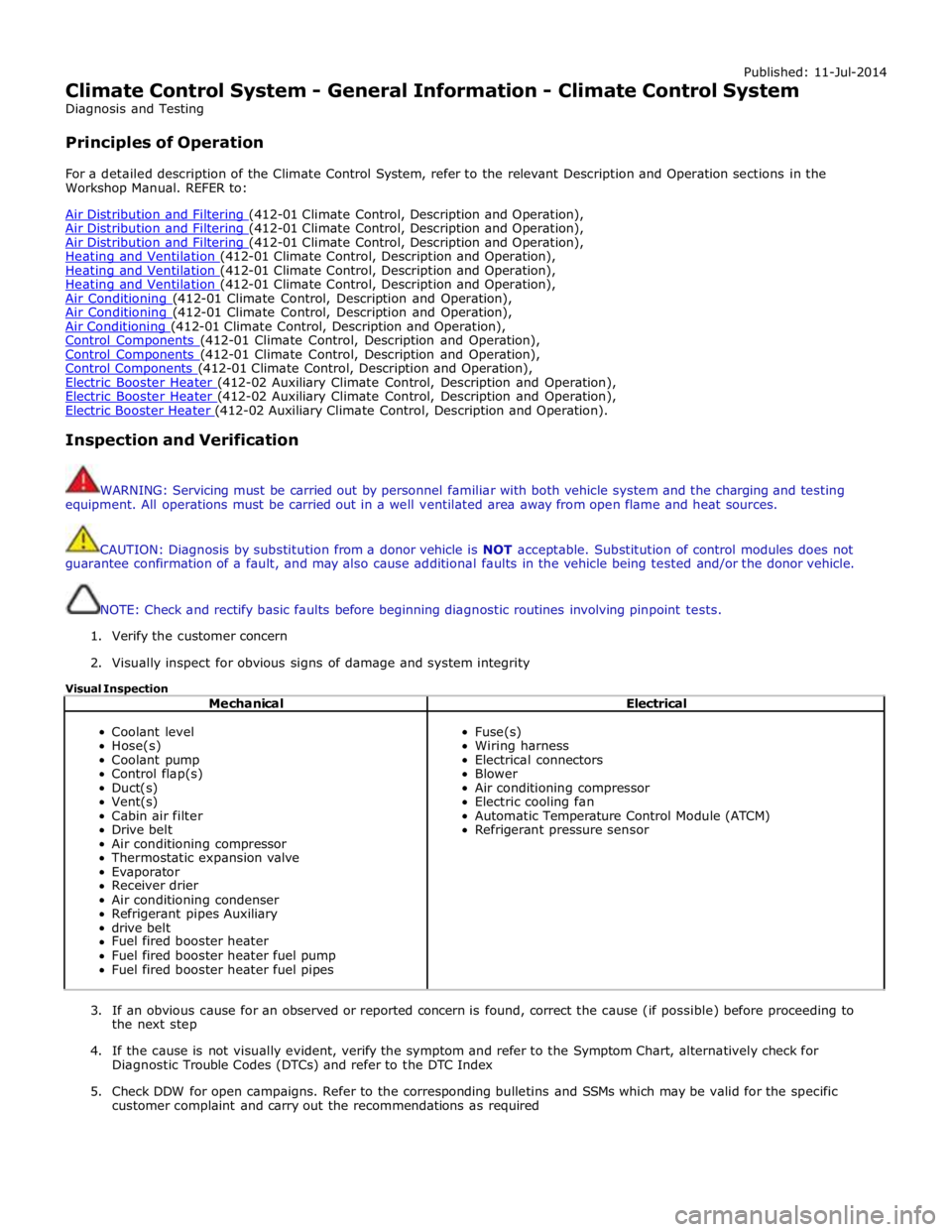
Visual Inspection
Mechanical Electrical
Coolant level
Hose(s)
Coolant pump
Control flap(s)
Duct(s)
Vent(s)
Cabin air filter
Drive belt
Air conditioning compressor
Thermostatic expansion valve
Evaporator
Receiver drier
Air conditioning condenser
Refrigerant pipes Auxiliary
drive belt
Fuel fired booster heater
Fuel fired booster heater fuel pump
Fuel fired booster heater fuel pipes
Fuse(s)
Wiring harness
Electrical connectors
Blower
Air conditioning compressor
Electric cooling fan
Automatic Temperature Control Module (ATCM)
Refrigerant pressure sensor
3. If an obvious cause for an observed or reported concern is found, correct the cause (if possible) before proceeding to
the next step
4. If the cause is not visually evident, verify the symptom and refer to the Symptom Chart, alternatively check for
Diagnostic Trouble Codes (DTCs) and refer to the DTC Index
5. Check DDW for open campaigns. Refer to the corresponding bulletins and SSMs which may be valid for the specific
customer complaint and carry out the recommendations as required
Page 1700 of 3039
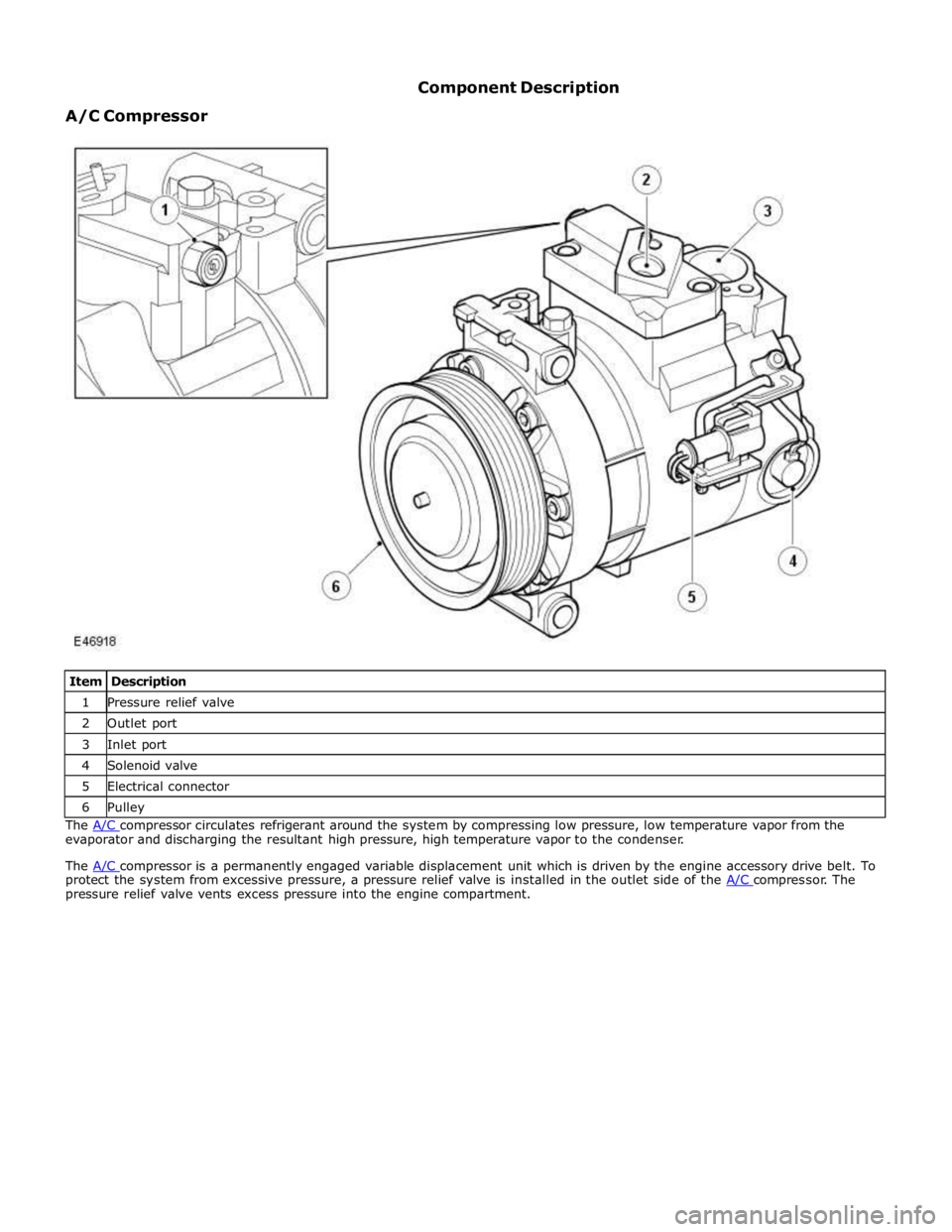
1 Pressure relief valve 2 Outlet port 3 Inlet port 4 Solenoid valve 5 Electrical connector 6 Pulley The A/C compressor circulates refrigerant around the system by compressing low pressure, low temperature vapor from the evaporator and discharging the resultant high pressure, high temperature vapor to the condenser.
The A/C compressor is a permanently engaged variable displacement unit which is driven by the engine accessory drive belt. To protect the system from excessive pressure, a pressure relief valve is installed in the outlet side of the A/C compressor. The pressure relief valve vents excess pressure into the engine compartment.
Page 1712 of 3039
bus. Temperature control for the heater element is provided by the steering wheel heater control module which receives a
temperature feedback signal from a NTC (negative temperature coefficient) thermistor located within the steering wheel.
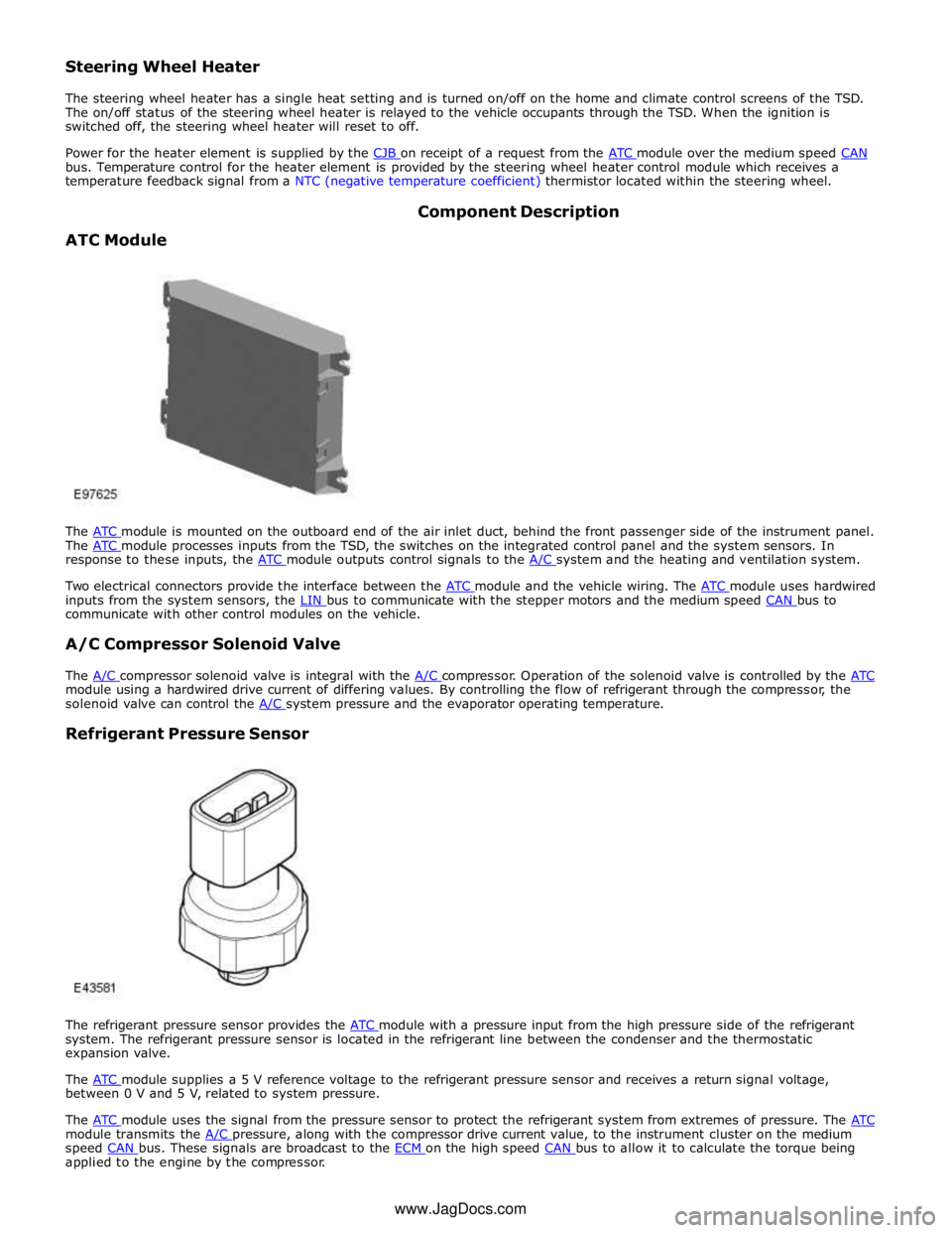
ATC Module Component Description
The ATC module is mounted on the outboard end of the air inlet duct, behind the front passenger side of the instrument panel. The ATC module processes inputs from the TSD, the switches on the integrated control panel and the system sensors. In response to these inputs, the ATC module outputs control signals to the A/C system and the heating and ventilation system.
Two electrical connectors provide the interface between the ATC module and the vehicle wiring. The ATC module uses hardwired inputs from the system sensors, the LIN bus to communicate with the stepper motors and the medium speed CAN bus to communicate with other control modules on the vehicle.
A/C Compressor Solenoid Valve
The A/C compressor solenoid valve is integral with the A/C compressor. Operation of the solenoid valve is controlled by the ATC module using a hardwired drive current of differing values. By controlling the flow of refrigerant through the compressor, the
solenoid valve can control the A/C system pressure and the evaporator operating temperature.
Refrigerant Pressure Sensor
The refrigerant pressure sensor provides the ATC module with a pressure input from the high pressure side of the refrigerant system. The refrigerant pressure sensor is located in the refrigerant line between the condenser and the thermostatic
expansion valve.
The ATC module supplies a 5 V reference voltage to the refrigerant pressure sensor and receives a return signal voltage, between 0 V and 5 V, related to system pressure.
The ATC module uses the signal from the pressure sensor to protect the refrigerant system from extremes of pressure. The ATC module transmits the A/C pressure, along with the compressor drive current value, to the instrument cluster on the medium speed CAN bus. These signals are broadcast to the ECM on the high speed CAN bus to allow it to calculate the torque being applied to the engine by the compressor. www.JagDocs.com
Page 1767 of 3039
7 ECT (engine coolant temperature) sensor 8 Ambient temperature sensor 9 Electric booster heater 10 Face/Feet distribution stepper motor 11 RH (right-hand) temperature blend stepper motor 12 LH (left-hand) temperature blend stepper motor 13 Windshield (defrost) distribution stepper motor 14 ATC (automatic temperature control) module 15 150 A megafuse
General System Operation
Operation of the electric booster heater is controlled by the ATC module, which communicates with the micro-controller in the booster heater using the LIN bus. The temperature requested by the ATC module is based on:
The ambient air temperature.
The engine coolant temperature.
The temperatures selected on the integrated control panel.
The blower must be running for the electric booster heater to operate.
If electrical load management is in force, electric booster heater performance is reduced. For additional information, refer to:
Electronic Engine Controls (303-14A, Description and Operation),
Electronic Engine Controls (303-14B Electronic Engine Controls - V6 3.0L Petrol, Description and Operation), Electronic Engine Controls (303-14C, Description and Operation).
Electric Booster Heater Component Description
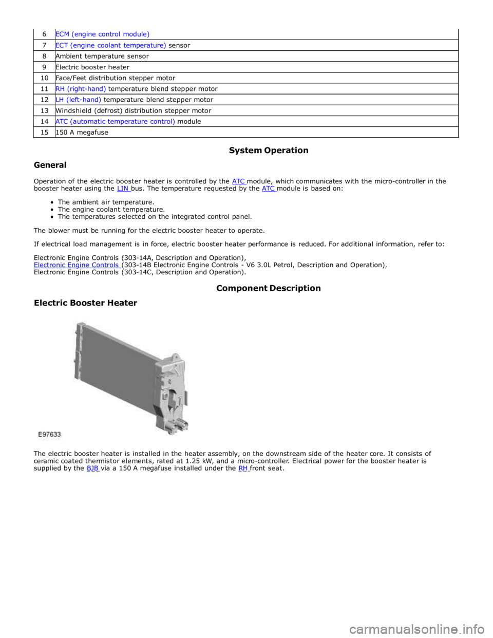
The electric booster heater is installed in the heater assembly, on the downstream side of the heater core. It consists of
ceramic coated thermistor elements, rated at 1.25 kW, and a micro-controller. Electrical power for the booster heater is
supplied by the BJB via a 150 A megafuse installed under the RH front seat.