2010 JAGUAR XFR warning
[x] Cancel search: warningPage 1577 of 3039
Fuel System - General Information - Quick Release Coupling
General Procedures
Disconnect Published: 11-May-2011
1. WARNINGS:
Place the vehicle in a quarantined area and arrange "No
Smoking/Petrol Fumes" signs about the vehicle.
Before any work is carried out on the fuel system, ground the
vehicle to earth and maintain the ground connection until the work is
complete.
Do not smoke or carry lighted tobacco or open flame of any type
when working on or near any fuel related components. Highly flammable
vapors are always present and may ignite. Failure to follow these
instructions may result in personal injury.
The fuel system remains pressurized for a long time after the
ignition is switched off. The fuel pressure must be relieved before
attempting any repairs. Failure to follow these instructions may result in
personal injury.
After carrying out repairs, the fuel system must be checked visually
for leaks. Failure to follow these instructions may result in personal
injury.
This procedure involves fuel handling. Be prepared for fuel spillage
at all times and always observe fuel handling precautions. Failure to
follow these instructions may result in personal injury.
If taken internally do not induce vomiting, seek immediate medical
attention. Failure to follow these instructions may result in personal
injury.
If fuel contacts the eyes, flush the eyes with cold water or
eyewash solution and seek medical attention.
Wash hands thoroughly after handling, as prolonged contact may
cause irritation. Should irritation develop, seek medical attention.
Relieve the fuel system pressure. For additional information, refer to the
procedure in this section: Pressure Relief.
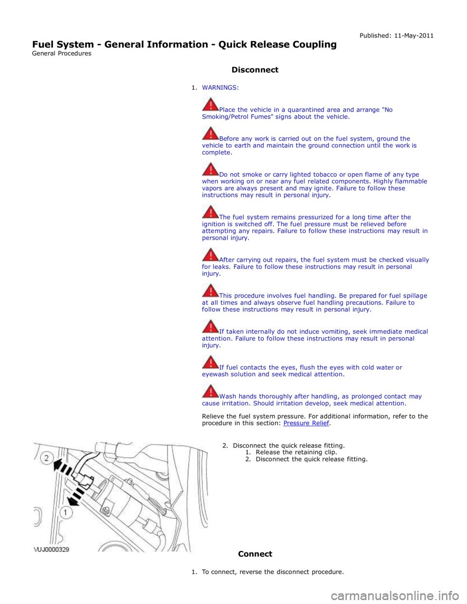
2. Disconnect the quick release fitting.
1. Release the retaining clip.
2. Disconnect the quick release fitting.
Connect
1. To connect, reverse the disconnect procedure.
Page 1578 of 3039
Published: 11-May-2011
Fuel System - General Information - Quick Release Coupling - Push Connect
General Procedures
Disconnect
1. WARNINGS:
Place the vehicle in a quarantined area and arrange "No
Smoking/Petrol Fumes" signs about the vehicle.
Before any work is carried out on the fuel system, ground the
vehicle to earth and maintain the ground connection until the work is
complete.
Do not smoke or carry lighted tobacco or open flame of any type
when working on or near any fuel related components. Highly flammable
vapors are always present and may ignite. Failure to follow these
instructions may result in personal injury.
The fuel system remains pressurized for a long time after the
ignition is switched off. The fuel pressure must be relieved before
attempting any repairs. Failure to follow these instructions may result in
personal injury.
After carrying out repairs, the fuel system must be checked visually
for leaks. Failure to follow these instructions may result in personal
injury.
This procedure involves fuel handling. Be prepared for fuel spillage
at all times and always observe fuel handling precautions. Failure to
follow these instructions may result in personal injury.
If taken internally do not induce vomiting, seek immediate medical
attention. Failure to follow these instructions may result in personal
injury.
If fuel contacts the eyes, flush the eyes with cold water or
eyewash solution and seek medical attention.
Wash hands thoroughly after handling, as prolonged contact may
cause irritation. Should irritation develop, seek medical attention.
Relieve the fuel system pressure. For additional information, refer to the
procedure in this section:
For additional information, refer to: Fuel System Pressure Release
(310-00 Fuel System - General Information, General Procedures).
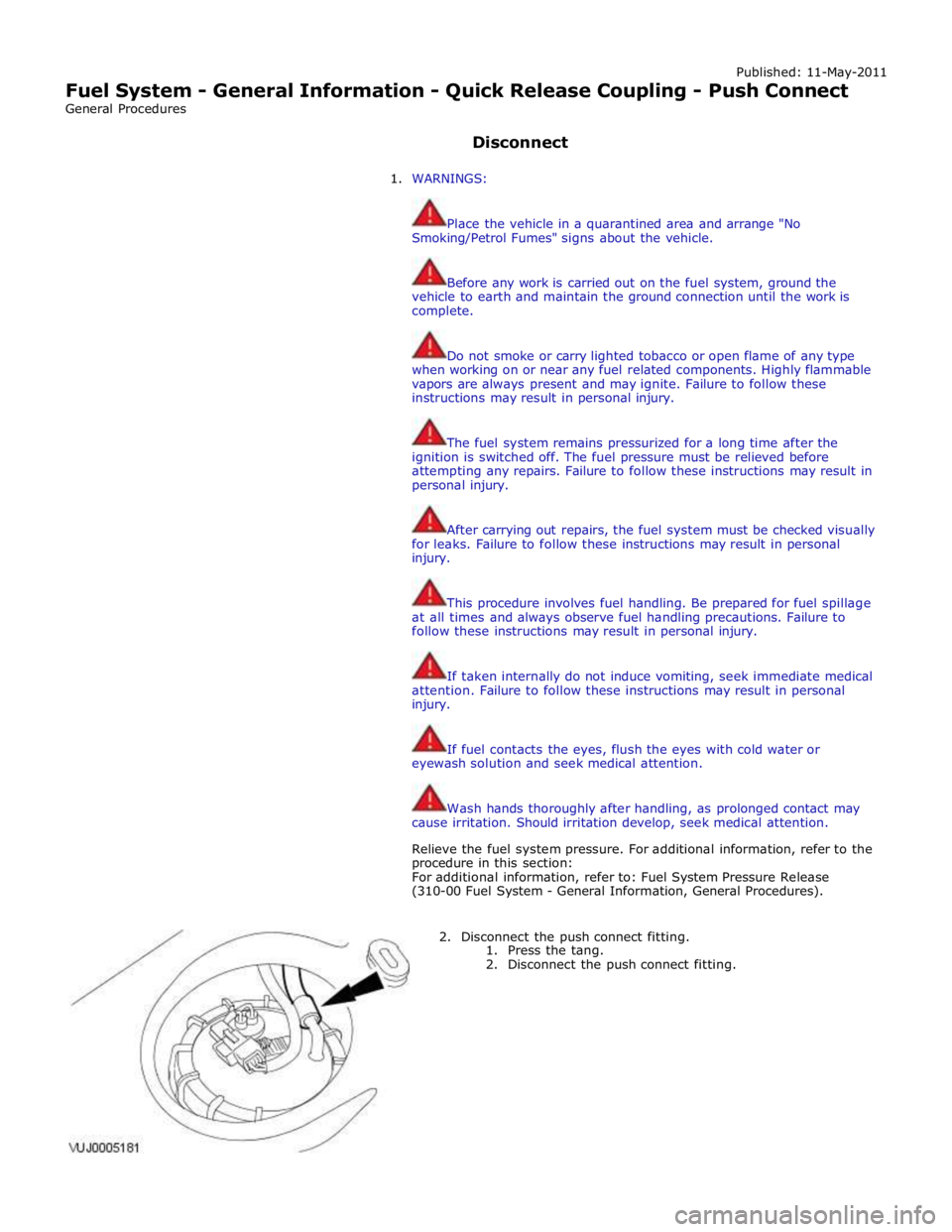
2. Disconnect the push connect fitting.
1. Press the tang.
2. Disconnect the push connect fitting.
Page 1591 of 3039
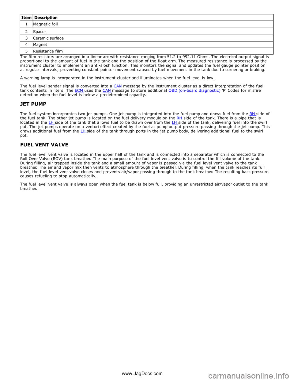
1 Magnetic foil 2 Spacer 3 Ceramic surface 4 Magnet 5 Resistance film The film resistors are arranged in a linear arc with resistance ranging from 51.2 to 992.11 Ohms. The electrical output signal is
proportional to the amount of fuel in the tank and the position of the float arm. The measured resistance is processed by the
instrument cluster to implement an anti-slosh function. This monitors the signal and updates the fuel gauge pointer position
at regular intervals, preventing constant pointer movement caused by fuel movement in the tank due to cornering or braking.
A warning lamp is incorporated in the instrument cluster and illuminates when the fuel level is low.
The fuel level sender signal is converted into a CAN message by the instrument cluster as a direct interpretation of the fuel tank contents in liters. The ECM uses the CAN message to store additional OBD (on-board diagnostic) 'P' Codes for misfire detection when the fuel level is below a predetermined capacity.
JET PUMP
The fuel system incorporates two jet pumps. One jet pump is integrated into the fuel pump and draws fuel from the RH side of the fuel tank. The other jet pump is located on the fuel delivery module on the RH side of the tank. There is a pipe that is located in the LH side of the tank that allows fuel to be drawn over from the LH side of the tank, delivering fuel into the swirl pot. The jet pumps operate on a venturi effect created by the fuel at pump output pressure passing through the jet pump. This
draws additional fuel from the LH side of the tank through ports in the jet pump body, delivering additional fuel to the swirl pot.
FUEL VENT VALVE
The fuel level vent valve is located in the upper half of the tank and is connected into a separator which is connected to the
Roll Over Valve (ROV) tank breather. The main purpose of the fuel level vent valve is to control the fill volume of the tank.
During filling, air trapped inside the tank and a small amount of vapor is passed via the fuel level vent valve to the tank
breather. The air and vapor mix then vents to atmosphere through the breather. During filling, when the tank reaches its full
level, the fuel level vent valve closes and prevents air/vapor passing through to the tank breather. The resulting back pressure
causes refueling to stop automatically.
The fuel level vent valve is always open when the fuel tank is below full, providing an unrestricted air/vapor outlet to the tank
breather.
www.JagDocs.com
Page 1595 of 3039
Published: 28-Jul-2014
Fuel Tank and Lines - V8 5.0L Petrol/V8 S/C 5.0L Petrol - Fuel Tank and
Lines
Diagnosis and Testing
Principle of Operation
For a detailed description of the fuel tank and lines system and operation, refer to the relevant Description and Operation
section of the workshop manual. REFER to: (310-01C Fuel Tank and Lines - V8 5.0L Petrol/V8 S/C 5.0L Petrol)
Fuel Tank and Lines (Description and Operation), Fuel Tank and Lines (Description and Operation), Fuel Tank and Lines (Description and Operation).
Inspection and Verification
WARNINGS:
Eye protection must be worn at all times when working on or near any fuel related components. Failure to follow this
instruction may result in personal injury.
This procedure involves fuel handling. Be prepared for fuel spillage at all times and always observe fuel handling
precautions. Failure to follow this instruction may result in personal injury.
After carrying out repairs, the fuel system must be checked visually for leaks. This should be done after the engine has
been run, but with the engine switched OFF. Failure to follow this instruction may result in personal injury.
If taken internally, DO NOT induce vomiting. Seek immediate medical attention. Failure to follow this instruction may
result in personal injury.
If fuel contacts the eyes, flush the eyes with cold water or eyewash solution and seek medical attention. Failure to follow
this instruction may result in personal injury.
Wash hands thoroughly after handling, as prolonged contact may cause irritation. Should irritation develop, seek medical
attention. Failure to follow this instruction may result in personal injury.
CAUTIONS:
Before disconnecting any part of the system, it is imperative that all dust, dirt and debris is removed from around
components to prevent ingress of foreign matter into the fuel system. Failure to follow this instruction may result in damage to
the vehicle.
It is essential that absolute cleanliness is observed when working with these components. Always install blanking plugs
to any open orifices or lines. Failure to follow this instruction may result in damage to the vehicle.
Diagnosis by substitution from a donor vehicle is NOT acceptable. Substitution of control modules does not guarantee
confirmation of a fault, and may also cause additional faults in the vehicle being tested and/or the donor vehicle.
NOTES:
Check and rectify basic faults before beginning diagnostic routines involving pinpoint tests.
When measuring fuel sender resistance values with a multimeter, it is critical to use the correct multimeter setting. The
multimeter should not be on the 'Auto' setting and must be set to 'Manual'. This will help prevent incorrect diagnosis and
unnecessary replacement of fuel senders. If the multimeter range is set at 'Auto' then, during a sweep of the sender from 50
Ohms to 998 Ohms, the multimeter has to change its measurement range. For approximately 1 second, during the range switch
over point, the multimeter display indicates an open circuit. This can lead to a mis-diagnosis of a fuel sender fault.
1. Verify the customer concern
2. Visually inspect for obvious signs of damage and system integrity
Page 1600 of 3039
Published: 09-Dec-2012
Fuel Tank and Lines - V8 5.0L Petrol/V8 S/C 5.0L Petrol - Fuel Pump and
Sender Unit
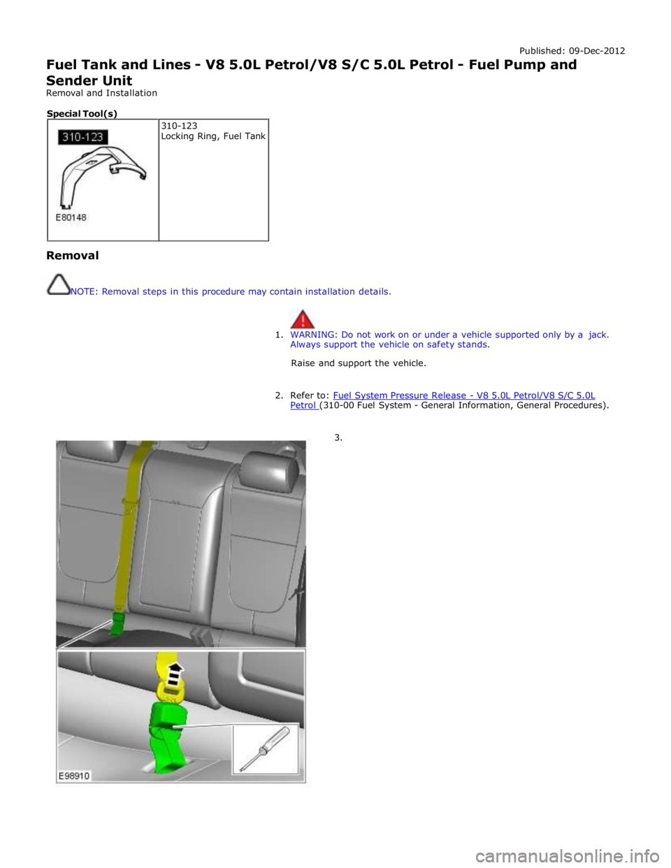
Removal and Installation
Removal
NOTE: Removal steps in this procedure may contain installation details.
1. WARNING: Do not work on or under a vehicle supported only by a jack.
Always support the vehicle on safety stands.
Raise and support the vehicle.
2. Refer to: Fuel System Pressure Release - V8 5.0L Petrol/V8 S/C 5.0L Petrol (310-00 Fuel System - General Information, General Procedures).
3. 310-123
Locking Ring, Fuel Tank Special Tool(s)
Page 1605 of 3039
Published: 11-May-2011
Fuel Tank and Lines - V8 5.0L Petrol/V8 S/C 5.0L Petrol - Fuel Tank
Removal and Installation
Removal
NOTE: Removal steps in this procedure may contain installation details.
1. Refer to: Petrol and Petrol-Ethanol Fuel Systems Health and Safety Precautions (100-00 General Information, Description and Operation).
2. Refer to: Battery Disconnect and Connect (414-01 Battery, Mounting and Cables, General Procedures).
3. Refer to: Fuel Tank Draining (310-00 Fuel System - General Information, General Procedures).
4. WARNING: Do not work on or under a vehicle supported only by a jack.
Always support the vehicle on safety stands.
Raise and support the vehicle.
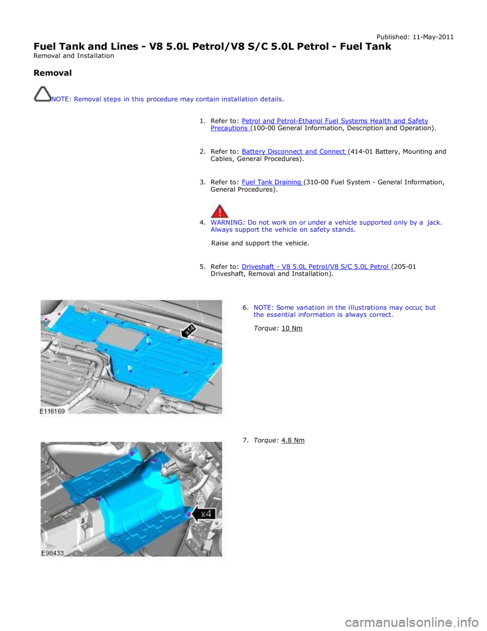
5. Refer to: Driveshaft - V8 5.0L Petrol/V8 S/C 5.0L Petrol (205-01 Driveshaft, Removal and Installation).
6. NOTE: Some variation in the illustrations may occur, but
the essential information is always correct.
Torque: 10 Nm
7. Torque: 4.8 Nm
Page 1606 of 3039
8.
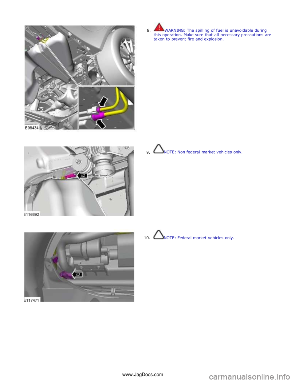
9.
10. WARNING: The spilling of fuel is unavoidable during
this operation. Make sure that all necessary precautions are
taken to prevent fire and explosion.
NOTE: Non federal market vehicles only.
NOTE: Federal market vehicles only. www.JagDocs.com
Page 1607 of 3039
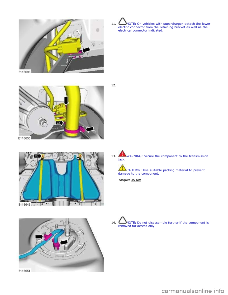
11.
12. NOTE: On vehicles with supercharger, detach the lower
electric connector from the retaining bracket as well as the
electrical connector indicated.
13.
jack.
WARNING: Secure the component to the transmission
CAUTION: Use suitable packing material to prevent
damage to the component.
Torque: 35 Nm
14. NOTE: Do not disassemble further if the component is
removed for access only.