2010 JAGUAR XFR stop start
[x] Cancel search: stop startPage 1080 of 3039
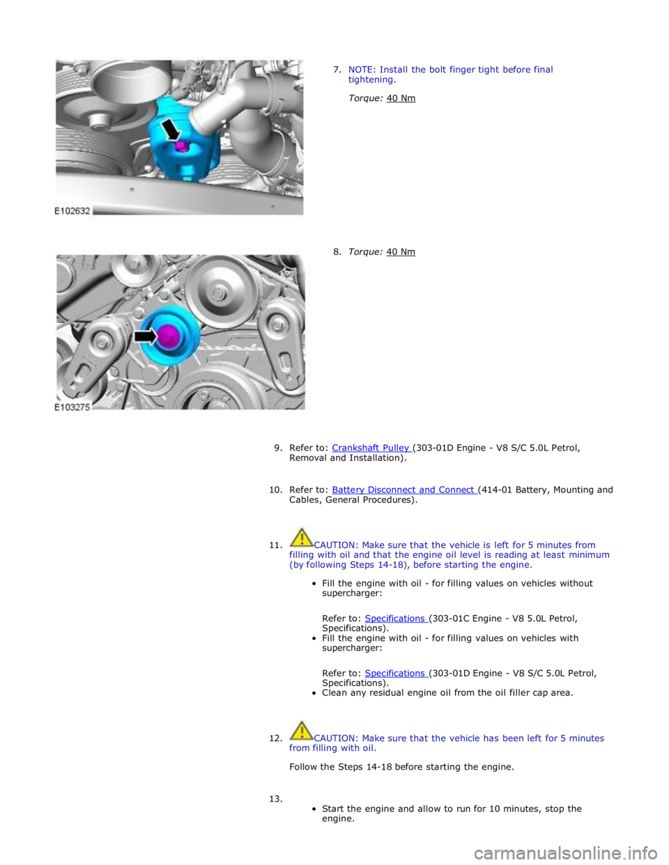
7. NOTE: Install the bolt finger tight before final
tightening.
Torque: 40 Nm
8. Torque: 40 Nm
9. Refer to: Crankshaft Pulley (303-01D Engine - V8 S/C 5.0L Petrol, Removal and Installation).
10. Refer to: Battery Disconnect and Connect (414-01 Battery, Mounting and Cables, General Procedures).
11. CAUTION: Make sure that the vehicle is left for 5 minutes from
filling with oil and that the engine oil level is reading at least minimum
(by following Steps 14-18), before starting the engine.
Fill the engine with oil - for filling values on vehicles without
supercharger:
Refer to: Specifications (303-01C Engine - V8 5.0L Petrol, Specifications).
Fill the engine with oil - for filling values on vehicles with
supercharger:
Refer to: Specifications (303-01D Engine - V8 S/C 5.0L Petrol, Specifications).
Clean any residual engine oil from the oil filler cap area.
12. CAUTION: Make sure that the vehicle has been left for 5 minutes
from filling with oil.
Follow the Steps 14-18 before starting the engine.
13.
Start the engine and allow to run for 10 minutes, stop the
engine.
Page 1124 of 3039
Proceed to the next step. A3 'Cooling fan is operating permanently' A3: COOLING FAN IS OPERATING PERMANENTLY 1 The cooling fan is operating permanently Is the customer reported symptom that the cooling fan is operating permanently at maximum speed?
Yes
The cooling fan is operating permanently
Proceed to the test step A5 'Cooling fan is operating permanently'
No
The cooling fan is NOT operating permanently
Proceed to the next step. A4 'Cooling fan is NOT operating' A4: COOLING FAN IS NOT OPERATING 1 The cooling fan is NOT operating Is the cooling fan NOT operating?
Yes
The cooling fan is NOT operating
Proceed to the test step A6 'Cooling fan is NOT operating'
No
No fault found. Verify customer concern of cooling fan operation A5: COOLING FAN IS OPERATING PERMANENTLY
WARNING: Moving parts can cause severe injury, keep clear of moving parts, never place your hands or any part of your
body near to moving parts 1 Using the manufacturer approved diagnostic system check datalogger signal – Electric Fan PWM Control - Commanded (0X03F9) - 2 Record the value of the datalogger signal – Electric Fan PWM Control - Commanded (0X03F9) - Is the value of the datalogger signal – Electric Fan PWM Control - Commanded (0X03F9) -between 5% &
16% whilst the cooling fan is operating?
Yes
The cooling fan should not be rotating in this PWM range
Refer to the electrical circuit diagrams and check the following circuit's for short circuit to ground, short
circuit to power, open circuit, high resistanceRefer to the electrical circuit diagrams and check the following
connectors for signs of water ingress, and pins for damage and/or corrosionEngine control module,
connector and wiringCircuit reference - ECFC -Cooling fan motor control unit connector and wiringCircuit
reference - VBATT -Circuit reference - IGN -Circuit reference - PWM -Circuit reference - GND -Battery
junction box, connector and wiringEngine junction box, connector and wiringCheck and install a new cooling
fan
No
Proceed to the next step. A6 'Cooling fan is NOT operating' A6: COOLING FAN IS NOT OPERATING
CAUTION: Ensure hood is closed and there are not any loose objects in front of the vehicle 1 Using the manufacturer approved diagnostic system command datalogger signal – Electric Fan PWM Control - Commanded (0X03F9) -to 30% Did the cooling fan start rotating?
Yes
Proceed to the next step. A7 'Electric Fan PWM Control'
No
Proceed to the step. A8 'Wiring check' A7: ELECTRIC FAN PWM CONTROL 1 Using the manufacturer approved diagnostic system command datalogger signal – Electric Fan PWM Control - Commanded (0X03F9) -to 90% Did the cooling fan rotating speed increase?
Yes
Using the manufacturer approved diagnostic system disable output state control function for this signal
and allow the cooling fan to stop rotating
No fault found. Verify customer concern of cooling fan operation
Proceed to the test step A9 'Cooling fan validation procedure'
No
Proceed to the step. A8 'Wiring check' A8: WIRING CHECK 1 Refer to the electrical circuit diagrams and check the following circuit's for short circuit to ground, short circuit to power, open circuit, high resistance 2 Refer to the electrical circuit diagrams and check the following connectors for signs of water ingress, and pins for damage and/or corrosion
Engine control module, connector and wiring
- Circuit reference - ECFC -
Cooling fan motor control unit connector and wiring
- Circuit reference - VBATT -
- Circuit reference - IGN -
- Circuit reference - PWM -
- Circuit reference - GND -
Battery junction box, connector and wiring
- Megafuses
Page 1344 of 3039
Published: 11-May-2011
Evaporative Emissions - V8 5.0L Petrol/V8 S/C 5.0L Petrol - Evaporative Emissions - System Operation and Component Description
Description and Operation
System Operation DIAGNOSTIC MODULE - TANK LEAKAGE PUMP (NAS ONLY)
To check the fuel tank and the EVAP (evaporative emission) system for leaks, the ECM (engine control module) operates the
DMTL pump and monitors the current draw. Initially, the ECM establishes a reference current by pumping air through the reference orifice and back to atmosphere. Once the reference current is determined, the ECM closes the change-over valve, which seals the EVAP system. The EVAP canister purge valve remains de-energized and is therefore closed. The output from the air pump is diverted from the reference orifice and into the EVAP system.
When the change-over valve is closed, the load on the air pump falls to zero. Providing there are no leaks, the air pump will
begin to pressurize the EVAP system and the load and current draw in the pump increases. By monitoring the rate and level of the current increase, the ECM can determine if there is a leak in the EVAP system.
During normal vehicle operation, 15 seconds after the engine has started, the ECM energizes the heating element in the pump to prevent condensation formation and possible incorrect readings. The heater remains energized until either the engine and
ignition are off (if no DMTL test is running) or until after the DMTL test is completed.
Leaks are classified as:
Minor - equivalent to a hole diameter of 0.5 to 1.0 mm (0.02 to 0.04 in.).
Major - equivalent to a hole diameter of 1.0 mm (0.04 in.) or greater.
The ECM performs a check for major leaks each time the ignition is switched off, providing the following conditions are met: The vehicle speed is zero.
The engine speed is zero.
The atmospheric pressure is above 70 kPa (10.15 lbf/in2
), i.e. the altitude is less than approximately 3047 m (10000
feet).
The ambient temperature is between 0 and 40 °C (32 and 104 °F).
The EVAP canister vapor concentration factor is 5 or less (where 0 is no fuel vapor, 1 is stoichiometric fuel vapor and greater than 1 is rich fuel vapor).
The fuel tank level is valid and between 15 and 85% of nominal capacity.
The engine running time during the previous cycle was more than 10 minutes.
The battery voltage is between 10 and 15 volts.
The last engine off time was more than 180 minutes.
No errors are detected with the EVAP components, the ambient air temperature and the fuel level.
NOTE: A leak test can be performed using a Jaguar recognized diagnostic tool. This overrides the above conditions and is
useful for checking correct system and component operation.
The ECM performs a check for minor leaks after every 2nd major leak check.
When the leak check is complete, the ECM stops the DMTL pump and opens (de-energizes) the change-over valve.
If the fuel filler cap is opened or refueling is detected during the leak check, by a sudden drop in the current draw or a rise in
the fuel level, the ECM aborts the leak check.
If a leak is detected during the check, the ECM stores an appropriate fault code in its memory. If a leak is detected on two consecutive checks, the ECM illuminates the MIL (malfunction indicator lamp) in the instrument cluster on the next drive cycle. The duration of a leak check can be between 60 and 900 seconds depending on the results and fuel tank level.
EVAP CANISTER PURGE VALVE
The ECM waits until the engine is running above 55 °C (131 °F) coolant temperature with closed loop fuel operational before the purging process is activated. Under these conditions the engine should be running smoothly with no warm up enrichment.
The EVAP canister purge valve duty (and flow) is initially ramped slowly because the vapor concentration is unknown (a sudden increase in purge could cause unstable engine running or cause it to stall due to an extremely "rich" air/fuel mixture). The
concentration is then determined from the amount of adjustment that the closed loop fueling is required to make to achieve
the target AFR (air fuel ratio). Once the concentration has been determined, the purge flow can be increased rapidly and the
injected fuel can be pro-actively adjusted to compensate for the known purge vapor and the target AIR control is maintained.
When the purging process is active, fresh air is drawn into the EVAP canister via the DMTL filter and pump on NAS vehicles, or via the vent port on the EVAP canister of non NAS vehicles.
Page 1345 of 3039
Component Description DIAGNOSTIC MODULE - TANK LEAKAGE PUMP (NAS ONLY)
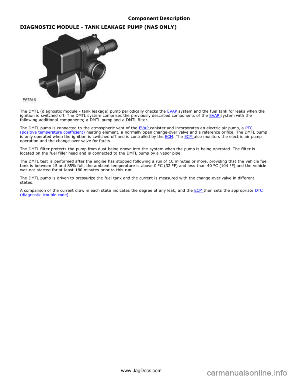
The DMTL (diagnostic module - tank leakage) pump periodically checks the EVAP system and the fuel tank for leaks when the ignition is switched off. The DMTL system comprises the previously described components of the EVAP system with the following additional components; a DMTL pump and a DMTL filter.
The DMTL pump is connected to the atmospheric vent of the EVAP canister and incorporates an electric air pump, a PTC (positive temperature coefficient) heating element, a normally open change-over valve and a reference orifice. The DMTL pump
is only operated when the ignition is switched off and is controlled by the ECM. The ECM also monitors the electric air pump operation and the change-over valve for faults.
The DMTL filter protects the pump from dust being drawn into the system when the pump is being operated. The filter is
located on the fuel filler head and is connected to the DMTL pump by a vapor pipe.
The DMTL test is performed after the engine has stopped following a run of 10 minutes or more, providing that the vehicle fuel
tank is between 15 and 85% full, the ambient temperature is above 0 °C (32 °F) and less than 40 °C (104 °F) and the vehicle
was not started for at least 180 minutes prior to this run.
The DMTL pump is driven to pressurize the fuel tank and the current is measured with the change-over valve in different
states.
A comparison of the current draw in each state indicates the degree of any leak, and the ECM then sets the appropriate DTC (diagnostic trouble code).
www.JagDocs.com
Page 1423 of 3039

The TCM can be reprogrammed using a Jaguar approved diagnostic system using a flash code. The TCM processor has a 440 kb internal flash memory. Of this capacity, approximately 370 kb are used by the basic transmission program. The remainder,
approximately 70 kb is used to store vehicle-specific application data.
Engine Stall
If the vehicle stalls it will coast down in gear, with the transmission providing drive to the engine. A restart can be attempted
at this point and the engine may start and the driver can continue.
If the coast down speed reduces such that the speed of the engine is less than 600 rev/min, the transmission will go to
neutral, D illumination will flash in the instrument cluster. The driver needs to select neutral or park and then press the brake
pedal to restart the engine.
If the start/stop button is pressed when driving, the message ENGINE STOP BUTTON PRESSED is displayed in the message
center but there will be no change to the ignition state. If the driver requires to switch off the engine, the start/stop button
must be pressed for a second time. The engine will be stopped and will be back driven by the transmission as the vehicle
coasts down. When the engine speed is less than 600 rev/min the transmission engages neutral (flashing D illumination in the
instrument cluster). When vehicle speed is less than 2 km/h (1.2 mph) Park is engaged. The JaguarDrive selector automatically
rotates back to its lowered P position and the vehicle ignition is switched off.
The park engagement is prevented in a stall case as the ignition power is on and D was the last selected gear. The park
engagement speed at ignition off is from the least value of the wheel speeds (CAN signal) and transmission output speed (internal signal).
TRANSMISSION Component Description
The transmission comprises the main casing which houses all of the transmission components. The main casing also
incorporates an integral bell housing.
A fluid pan is attached to the lower face of the main casing and is secured with bolts. The fluid pan is sealed to the main
casing with a gasket. Removal of the fluid pan allows access to the Mechatronic valve block. The fluid pan has a magnet
located around the drain plug which collects any metallic particles present in the transmission fluid.
A fluid filter is located inside the fluid pan. If the transmission fluid becomes contaminated or after any service work, the fluid
pan with integral filter must be replaced.
The integral bell housing provides protection for the torque converter assembly and also provides the attachment for the
gearbox to the engine cylinder block. The torque converter is a non-serviceable assembly which also contains the lock-up clutch
mechanism. The torque converter drives a crescent type pump via drive tangs. The fluid pump is located in the main casing,
behind the torque converter.
The main casing contains the following major components:
Input shaft
Output shaft
Mechatronic valve block which contains the solenoids, speed sensors and the TCM Three rotating multiplate drive clutches
Two fixed multiplate brake clutches
A single planetary gear train and a double planetary gear train.
Page 1531 of 3039
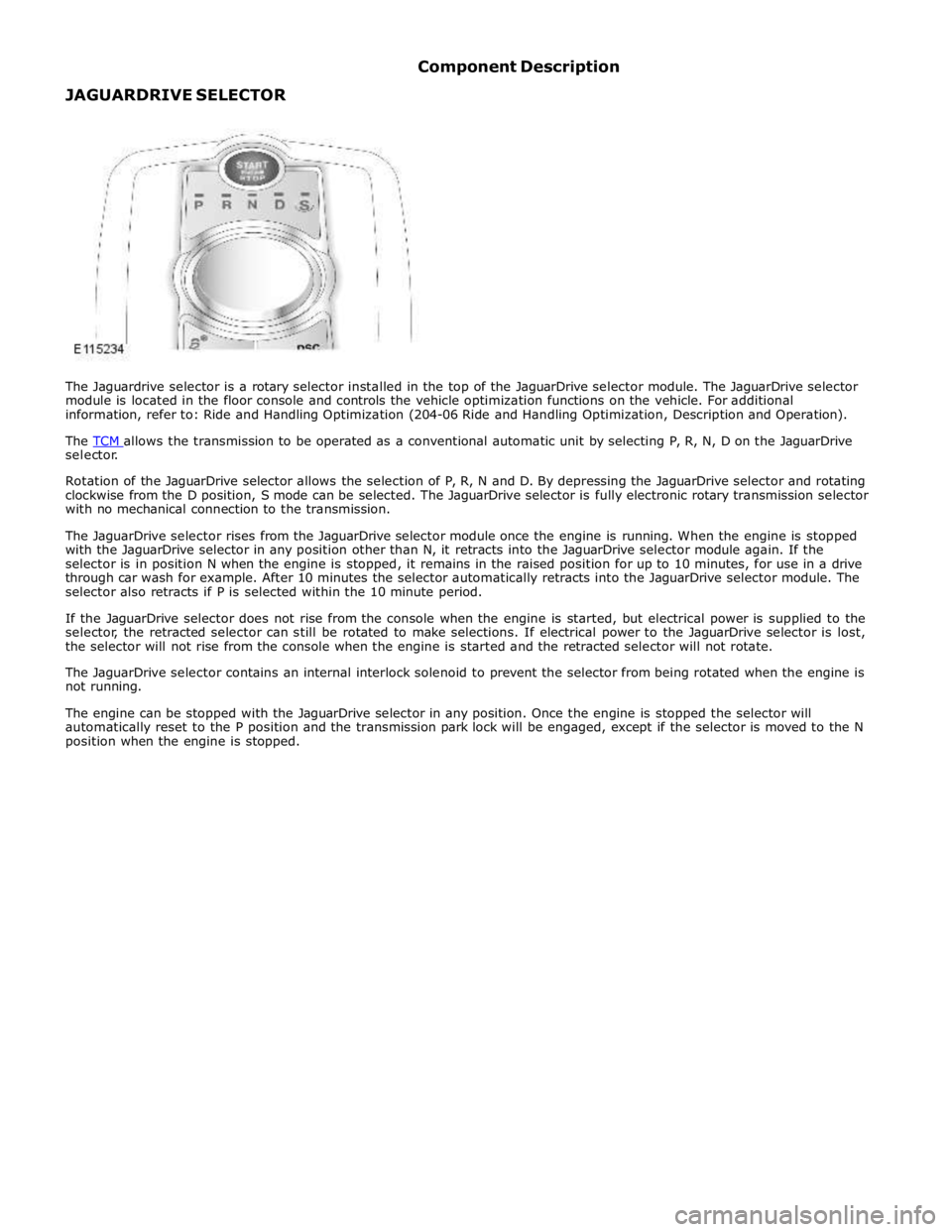
selector.
Rotation of the JaguarDrive selector allows the selection of P, R, N and D. By depressing the JaguarDrive selector and rotating
clockwise from the D position, S mode can be selected. The JaguarDrive selector is fully electronic rotary transmission selector
with no mechanical connection to the transmission.
The JaguarDrive selector rises from the JaguarDrive selector module once the engine is running. When the engine is stopped
with the JaguarDrive selector in any position other than N, it retracts into the JaguarDrive selector module again. If the
selector is in position N when the engine is stopped, it remains in the raised position for up to 10 minutes, for use in a drive
through car wash for example. After 10 minutes the selector automatically retracts into the JaguarDrive selector module. The
selector also retracts if P is selected within the 10 minute period.
If the JaguarDrive selector does not rise from the console when the engine is started, but electrical power is supplied to the
selector, the retracted selector can still be rotated to make selections. If electrical power to the JaguarDrive selector is lost,
the selector will not rise from the console when the engine is started and the retracted selector will not rotate.
The JaguarDrive selector contains an internal interlock solenoid to prevent the selector from being rotated when the engine is
not running.
The engine can be stopped with the JaguarDrive selector in any position. Once the engine is stopped the selector will
automatically reset to the P position and the transmission park lock will be engaged, except if the selector is moved to the N
position when the engine is stopped.
Page 1589 of 3039
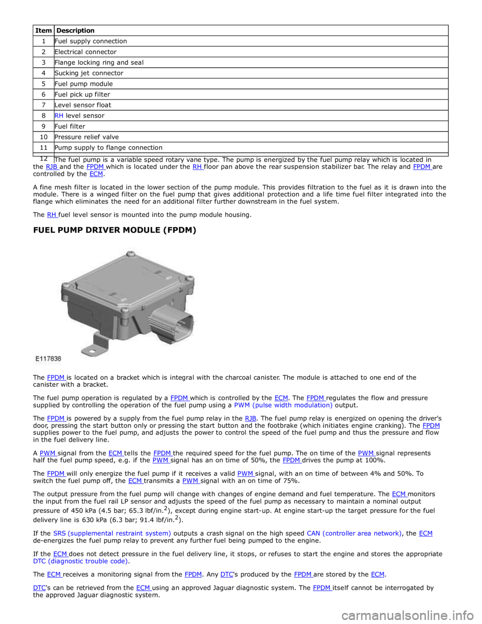
1 Fuel supply connection 2 Electrical connector 3 Flange locking ring and seal 4 Sucking jet connector 5 Fuel pump module 6 Fuel pick up filter 7 Level sensor float 8 RH level sensor 9 Fuel filter 10 Pressure relief valve 11 Pump supply to flange connection 12 The fuel pump is a variable speed rotary vane type. The pump is energized by the fuel pump relay which is located in the RJB and the FPDM which is located under the RH floor pan above the rear suspension stabilizer bar. The relay and FPDM are controlled by the ECM.
A fine mesh filter is located in the lower section of the pump module. This provides filtration to the fuel as it is drawn into the
module. There is a winged filter on the fuel pump that gives additional protection and a life time fuel filter integrated into the
flange which eliminates the need for an additional filter further downstream in the fuel system.
The RH fuel level sensor is mounted into the pump module housing.
FUEL PUMP DRIVER MODULE (FPDM)
The FPDM is located on a bracket which is integral with the charcoal canister. The module is attached to one end of the canister with a bracket.
The fuel pump operation is regulated by a FPDM which is controlled by the ECM. The FPDM regulates the flow and pressure supplied by controlling the operation of the fuel pump using a PWM (pulse width modulation) output.
The FPDM is powered by a supply from the fuel pump relay in the RJB. The fuel pump relay is energized on opening the driver's door, pressing the start button only or pressing the start button and the footbrake (which initiates engine cranking). The FPDM supplies power to the fuel pump, and adjusts the power to control the speed of the fuel pump and thus the pressure and flow
in the fuel delivery line.
A PWM signal from the ECM tells the FPDM the required speed for the fuel pump. The on time of the PWM signal represents half the fuel pump speed, e.g. if the PWM signal has an on time of 50%, the FPDM drives the pump at 100%.
The FPDM will only energize the fuel pump if it receives a valid PWM signal, with an on time of between 4% and 50%. To switch the fuel pump off, the ECM transmits a PWM signal with an on time of 75%.
The output pressure from the fuel pump will change with changes of engine demand and fuel temperature. The ECM monitors the input from the fuel rail LP sensor and adjusts the speed of the fuel pump as necessary to maintain a nominal output
pressure of 450 kPa (4.5 bar; 65.3 lbf/in.2
), except during engine start-up. At engine start-up the target pressure for the fuel
delivery line is 630 kPa (6.3 bar; 91.4 lbf/in.2
).
If the SRS (supplemental restraint system) outputs a crash signal on the high speed CAN (controller area network), the ECM de-energizes the fuel pump relay to prevent any further fuel being pumped to the engine.
If the ECM does not detect pressure in the fuel delivery line, it stops, or refuses to start the engine and stores the appropriate DTC (diagnostic trouble code).
The ECM receives a monitoring signal from the FPDM. Any DTC's produced by the FPDM are stored by the ECM.
DTC's can be retrieved from the ECM using an approved Jaguar diagnostic system. The FPDM itself cannot be interrogated by the approved Jaguar diagnostic system.
Page 1687 of 3039
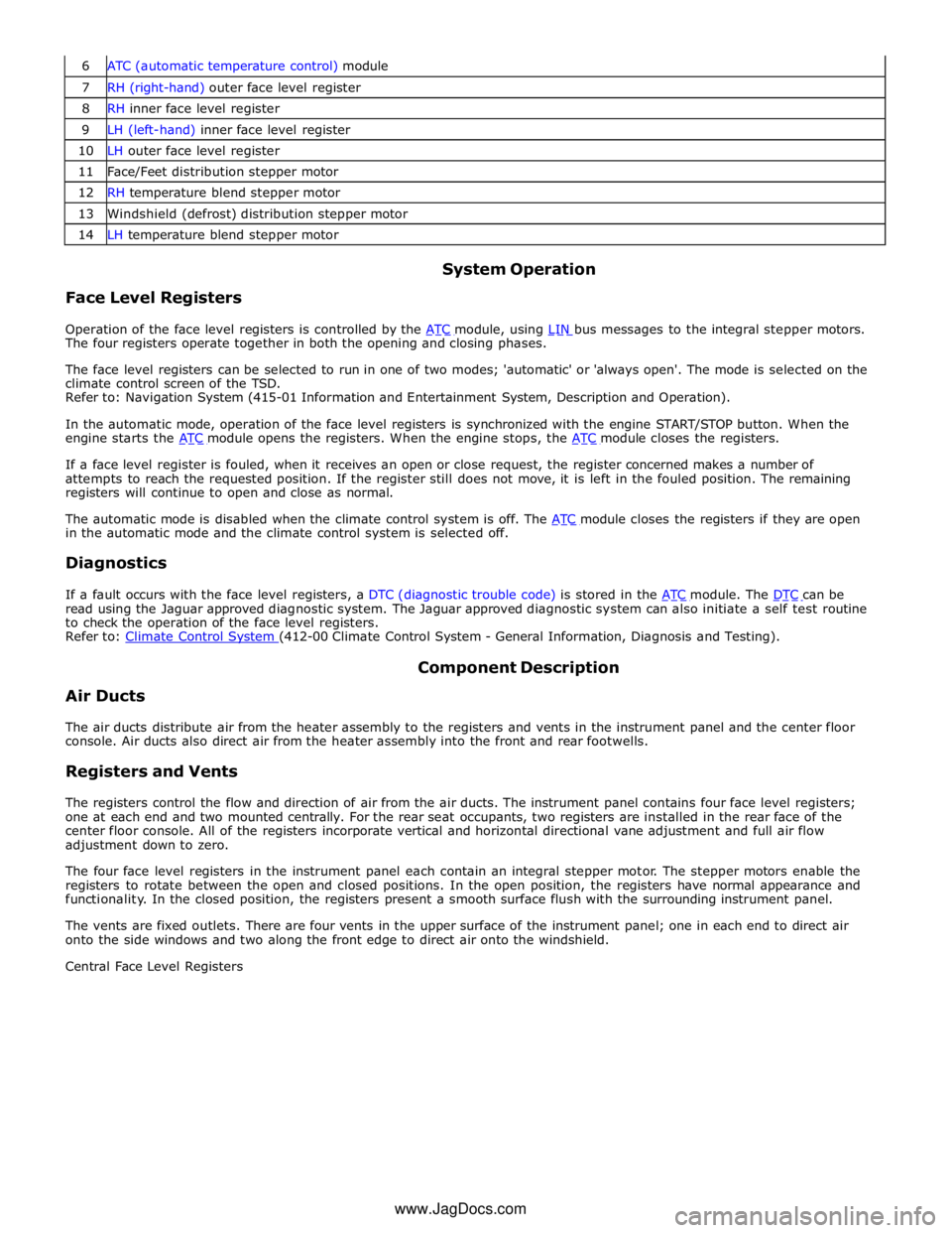
7 RH (right-hand) outer face level register 8 RH inner face level register 9 LH (left-hand) inner face level register 10 LH outer face level register 11 Face/Feet distribution stepper motor 12 RH temperature blend stepper motor 13 Windshield (defrost) distribution stepper motor 14 LH temperature blend stepper motor
Face Level Registers System Operation
Operation of the face level registers is controlled by the ATC module, using LIN bus messages to the integral stepper motors. The four registers operate together in both the opening and closing phases.
The face level registers can be selected to run in one of two modes; 'automatic' or 'always open'. The mode is selected on the
climate control screen of the TSD.
Refer to: Navigation System (415-01 Information and Entertainment System, Description and Operation).
In the automatic mode, operation of the face level registers is synchronized with the engine START/STOP button. When the
engine starts the ATC module opens the registers. When the engine stops, the ATC module closes the registers.
If a face level register is fouled, when it receives an open or close request, the register concerned makes a number of
attempts to reach the requested position. If the register still does not move, it is left in the fouled position. The remaining
registers will continue to open and close as normal.
The automatic mode is disabled when the climate control system is off. The ATC module closes the registers if they are open in the automatic mode and the climate control system is selected off.
Diagnostics
If a fault occurs with the face level registers, a DTC (diagnostic trouble code) is stored in the ATC module. The DTC can be read using the Jaguar approved diagnostic system. The Jaguar approved diagnostic system can also initiate a self test routine
to check the operation of the face level registers.
Refer to: Climate Control System (412-00 Climate Control System - General Information, Diagnosis and Testing).
Air Ducts Component Description
The air ducts distribute air from the heater assembly to the registers and vents in the instrument panel and the center floor
console. Air ducts also direct air from the heater assembly into the front and rear footwells.
Registers and Vents
The registers control the flow and direction of air from the air ducts. The instrument panel contains four face level registers;
one at each end and two mounted centrally. For the rear seat occupants, two registers are installed in the rear face of the
center floor console. All of the registers incorporate vertical and horizontal directional vane adjustment and full air flow
adjustment down to zero.
The four face level registers in the instrument panel each contain an integral stepper motor. The stepper motors enable the
registers to rotate between the open and closed positions. In the open position, the registers have normal appearance and
functionality. In the closed position, the registers present a smooth surface flush with the surrounding instrument panel.
The vents are fixed outlets. There are four vents in the upper surface of the instrument panel; one in each end to direct air
onto the side windows and two along the front edge to direct air onto the windshield.
Central Face Level Registers
www.JagDocs.com