2010 JAGUAR XFR park assist
[x] Cancel search: park assistPage 1651 of 3039

DTC Description Possible Causes Action for further assistance P0501-62
Vehicle Speed Sensor A
Range/Performance - Signal
compare failure
Vehicle speed - range
performance
Check ABS/TCM for related DTCs and refer
to relevant DTC Index P0504-00 Brake Switch A / B Correlation
- No sub type information
The brake pressure reading
does not agree with the
brake light switch value
Carry out any pinpoint tests associated with
this DTC using the manufacturer approved
diagnostic system. Refer to the electrical
circuit diagrams and check brake switch
circuits for short, open circuit, high
resistance P0504-01 Brake Switch A / B Correlation
- General electrical failure
Brake switch high fault:
- Brake lights stuck
on
- Gearshift interlock
inoperative
- Speed control
inoperative
Brake switch low fault:
- Brake lights
inoperative
- Gearshift stuck in
Park
- Reduced engine
braking
Carry out any pinpoint tests associated with
this DTC using the manufacturer approved
diagnostic system. Refer to the electrical
circuit diagrams and check brake switch
circuits for short, open circuit, high
resistance P0566-00
Cruise Control OFF Signal - No
sub type information
Speed control Cancel
switch 2 stuck closed
Refer to the electrical circuit diagrams and
check speed control switch circuits for short,
open circuit. Check for stuck switch. Check
and install a new speed control switch as
required P0567-00
Cruise Control DECREASE
DISTANCE Signal - No sub
type information
Speed control Resume
switch 7 stuck closed
Refer to the electrical circuit diagrams and
check speed control switch circuits for short,
open circuit. Check for stuck switch. Check
and install a new speed control switch as
required P0568-00
Cruise Control INCREASE
DISTANCE Signal - No sub
type information
Speed control Accel Set
Plus Switch 6 stuck closed
Check and install a new speed control
switch as required P0569-00
Cruise Control COAST Signal -
No sub type information
Speed control Coast Set
Minus switch 3 stuck
closed
Refer to the electrical circuit diagrams and
check speed control switch circuits for short,
open circuit. Check for stuck switch. Check
and install a new speed control switch as
required P056A-00
Cruise Control INCREASE
DISTANCE Signal - No sub
type information
Speed control Headway
Plus switch 4 stuck closed
Refer to the electrical circuit diagrams and
check speed control switch circuits for short,
open circuit. Check for stuck switch. Check
and install a new speed control switch as
required P056B-00
Cruise Control DECREASE
DISTANCE Signal - No sub
type information
Speed control Headway
Minus switch 5 stuck
closed
Refer to the electrical circuit diagrams and
check speed control switch circuits for short,
open circuit. Check for stuck switch. Check
and install a new speed control switch as
required P0571-62
Brake Switch A Circuit - Signal
compare failure
Plausibility error
Refer to the electrical circuit diagrams and
check brake light switch signal circuits for
short, open circuit. Check and install a new
brake light switch as required P0575-01
Cruise Control Input Circuit -
General electrical failure
General electrical failure
Check speed control system for related
DTCs and refer to relevant DTC Index. Carry
out CAN network integrity tests using the
Page 1786 of 3039
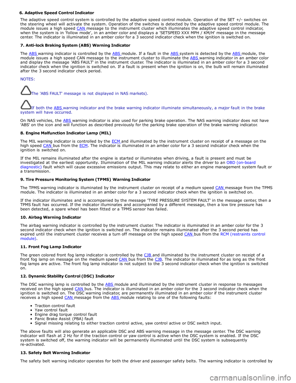
6. Adaptive Speed Control Indicator
The adaptive speed control system is controlled by the adaptive speed control module. Operation of the SET +/- switches on
the steering wheel will activate the system. Operation of the switches is detected by the adaptive speed control module. The
module issues a high speed CAN message to the instrument cluster which illuminates the adaptive speed control indicator, when the system is in 'follow mode', in an amber color and displays a 'SETSPEED XXX MPH / KM/H' message in the message
center. The indicator is illuminated in an amber color for a 3 second indicator check when the ignition is switched on.
7. Anti-lock Braking System (ABS) Warning Indicator
The ABS warning indicator is controlled by the ABS module. If a fault in the ABS system is detected by the ABS module, the module issues a high speed CAN message to the instrument cluster to illuminate the ABS warning indicator in an amber color and display the message 'ABS FAULT' in the instrument cluster. The indicator is illuminated in an amber color for a 3 second
indicator check when the ignition is switched on. If a fault is present when the ignition is on, the bulb will remain illuminated
after the 3 second indicator check period.
NOTES:
The 'ABS FAULT' message is not displayed in NAS markets).
If both the ABS warning indicator and the brake warning indicator illuminate simultaneously, a major fault in the brake system will have occurred.
On NAS vehicles, the ABS warning indicator is also used for parking brake operation. The NAS warning indicator does not have 'ABS' on the icon and will function as described previously for the parking brake operation of the brake warning indicator.
8. Engine Malfunction Indicator Lamp (MIL)
The MIL warning indicator is controlled by the ECM and illuminated by the instrument cluster on receipt of a message on the high speed CAN bus from the ECM. The indicator is illuminated in an amber color for a 3 second indicator check when the ignition is switched on.
If the MIL remains illuminated after the engine is started or illuminates when driving, a fault is present and must be
investigated at the earliest opportunity. Illumination of the MIL warning indicator alerts the driver to an OBD (on-board
diagnostic) fault which will cause excessive emissions output. This may relate to either an engine management system fault or
a transmission.
9. Tire Pressure Monitoring System (TPMS) Warning Indicator
The TPMS warning indicator is illuminated by the instrument cluster on receipt of a medium speed CAN message from the TPMS module. The indicator is illuminated in an amber color for a 3 second indicator check when the ignition is switched on.
If the indicator illuminates and is accompanied by the message 'TYRE PRESSURE SYSTEM FAULT' in the message center, then a
TPMS fault has occurred. If the indicator illuminates and accompanied by a different message, then a low tire pressure has
been detected, a spare wheel has been fitted or a TPMS sensor has failed.
10. Airbag Warning Indicator
The airbag warning indicator is controlled by the instrument cluster. The indicator is illuminated in an amber color for the 3
second indicator check when the ignition is switched on. The indicator remains illuminated after the 3 second period has
expired until the instrument cluster receives a turn off message on the high speed CAN bus from the RCM (restraints control module).
11. Front Fog Lamp Indicator
The green colored front fog lamp indicator is controlled by the CJB and illuminated by the instrument cluster on receipt of a front fog lamp on message on the medium speed CAN bus from the CJB. The indicator is illuminated for as long as the front fog lamps are active. The front fog lamp indicator is not subject to the 3 second indicator check when the ignition is switched
on.
12. Dynamic Stability Control (DSC) Indicator
The DSC warning lamp is controlled by the ABS module and illuminated by the instrument cluster in response to messages received on the high speed CAN bus. The indicator is illuminated in an amber color for the 3 second indicator check when the ignition is switched on. The DSC warning indicator, are permanently illuminated in an amber color if the instrument cluster
receives a high speed CAN message from the ABS module relating to one of the following faults:
Traction control fault
Yaw control fault
Engine drag torque control fault
Panic Brake Assist (PBA) fault
Signal missing relating to either traction control active, yaw control active or DSC switch input.
The above faults will also generate an applicable DSC and ABS warning message in the message center. The DSC warning
indicator will flash at 2 Hz for if the traction control or yaw control is active when the DSC system is enabled. If the DSC
system is switched off, the warning indicator will be permanently illuminated until the DSC system is subsequently
re-activated.
13. Safety Belt Warning Indicator
The safety belt warning indicator operates for both the driver and passenger safety belts. The warning indicator is controlled by
Page 1796 of 3039

ETM Test/no. Message Center Display Gauge/Indicator/Display
Tested.
Range
Description 25:XXX -
XXXX
26:XXX -
XXXX
27.XXX -
XXXX 25 - Passenger seat belt
26 - Not used
27 - On-board temp ref 18 - Analogue
Inputs.
ANALOG
INPUTS.
#: RAW -
Ratio
28:XXX -
XXXX
29:XXX -
XXXX
30:XXX -
XXXX
31.XXX -
XXXX Cluster inputs. TDB.
Displays Hex coding of inputs 28 -
31.
28 - On-board temp
29 - Not used
30 - Not used
31 - Not used 19 -
Speedometer. SPEEDOMETER.
RAW:
MPH:
KMH:
DRIVER: Speedometer inputs. .
Displays present .
Speedometer inputs values;
Speedometer will indicate
present road speed. 20 -
Tachometer. TACHOMETER.
RAW:
ACTUAL:
DRIVER: Tachometer inputs. .
Displays present received
Tachometer input values,
tachometer will indicate present
engine RPM. 21 - Fuel
system. FUEL SYSTEM.
(A) (B)
RAW: X X
FILT: X X
PERCENT: X X Fuel indication system. .
Displays present received fuel level
A/D inputs in decimal, fuel gauge
will indicate present filtered level. 22 - Battery
voltage. BATTERY VOLTAGE.
LOCAL:
VEHICLE:
RAW:
A/D: Battery voltage. .
Displays present received battery
input voltage values. If message not
received or invalid display will be '_
_ _'. 23 - Rolling
counts. ROLLING COUNTS.
ODO:
FUEL: Odometer and fuel gauge. 0 - 255.
Displays present received odometer
and fuel level input values in
decimal, value is a rolling count. If
either message not received or
invalid respective display will be ' _
_ _' . 24 - VAPS. VAPS.
CURRENT:
COMMAND:
STATUS: Variable assistance power
steering (VAPS) status. .
CURRENT is displayed in mA.
COMMAND is last command sent to
VAPS chip. STATUS is last status
returned from VAPS chip. 25 - Module MODULE STATUS. Provides status of; Ignition
CONNECTED
Communication (Coms) ok status. (IGN), Dynamic Stability Control IGN
(DSC), Adaptive Cruise Control WAITING Coms not received, not an DSC
(ACC) and Adaptive damping MISSING issue ACC
control module (ADCM) modules. FAULTY. Coms never received ADCM Coms error . 26 - Module MODULE STATUS. Provides status of; Electronic
CONNECTED
Communication (Coms) ok status. park brake (EPB), Pedestrian EPB
Impact ECU (PIE), Restraints WAITING Coms not received, not an PIE
control module (RCM) and MISSING issue RCM
Traction control module (TCM), FAULTY. Coms never received TCM
modules.. Coms error . 27 - Module
status. MODULE STATUS.
ECM
RCC Provides status of; Engine
control module (ECM), Rear
Climate Control (RCC), Driver
Door Control (DDC) and
CONNECTED
WAITING
MISSING
Communication (Coms) ok
Coms not received, not an
issue
Page 1823 of 3039
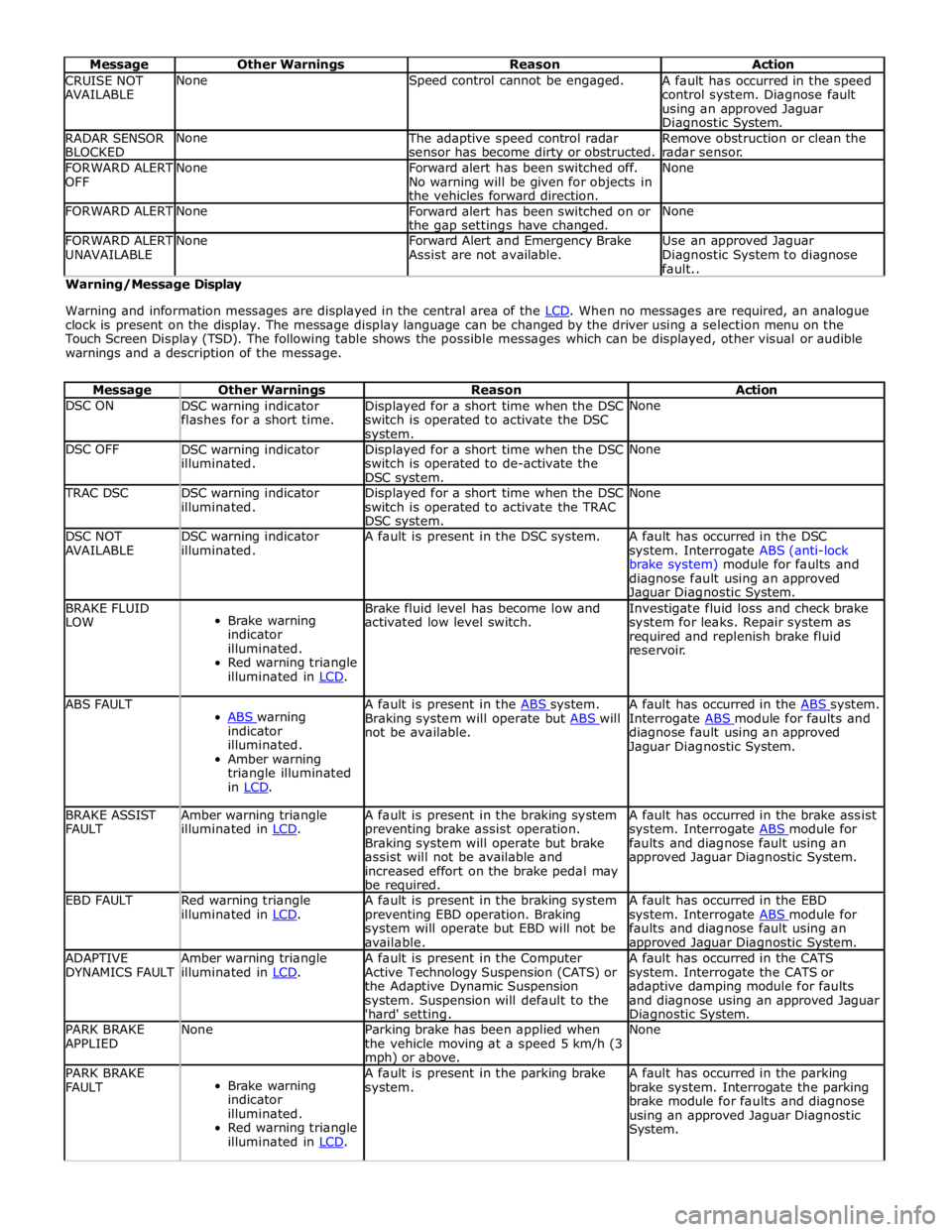
Message Other Warnings Reason Action CRUISE NOT
AVAILABLE None Speed control cannot be engaged.
A fault has occurred in the speed
control system. Diagnose fault
using an approved Jaguar Diagnostic System. RADAR SENSOR
BLOCKED None
The adaptive speed control radar
sensor has become dirty or obstructed. Remove obstruction or clean the
radar sensor. FORWARD ALERT
OFF None
Forward alert has been switched off.
No warning will be given for objects in
the vehicles forward direction. None FORWARD ALERT None
Forward alert has been switched on or
the gap settings have changed. None FORWARD ALERT
UNAVAILABLE None
Forward Alert and Emergency Brake
Assist are not available. Use an approved Jaguar
Diagnostic System to diagnose
fault.. Warning/Message Display
Warning and information messages are displayed in the central area of the LCD. When no messages are required, an analogue clock is present on the display. The message display language can be changed by the driver using a selection menu on the
Touch Screen Display (TSD). The following table shows the possible messages which can be displayed, other visual or audible
warnings and a description of the message.
Message Other Warnings Reason Action DSC ON
DSC warning indicator
flashes for a short time. Displayed for a short time when the DSC
switch is operated to activate the DSC system. None DSC OFF
DSC warning indicator
illuminated. Displayed for a short time when the DSC
switch is operated to de-activate the
DSC system. None TRAC DSC
DSC warning indicator
illuminated. Displayed for a short time when the DSC
switch is operated to activate the TRAC
DSC system. None DSC NOT
AVAILABLE DSC warning indicator
illuminated. A fault is present in the DSC system.
A fault has occurred in the DSC
system. Interrogate ABS (anti-lock
brake system) module for faults and
diagnose fault using an approved Jaguar Diagnostic System. BRAKE FLUID
LOW
Brake warning
indicator
illuminated.
Red warning triangle
illuminated in LCD. Brake fluid level has become low and
activated low level switch. Investigate fluid loss and check brake
system for leaks. Repair system as
required and replenish brake fluid
reservoir. ABS FAULT
ABS warning indicator
illuminated.
Amber warning
triangle illuminated
in LCD. A fault is present in the ABS system. Braking system will operate but ABS will not be available. A fault has occurred in the ABS system. Interrogate ABS module for faults and diagnose fault using an approved
Jaguar Diagnostic System. BRAKE ASSIST
FAULT Amber warning triangle
illuminated in LCD. A fault is present in the braking system
preventing brake assist operation.
Braking system will operate but brake
assist will not be available and
increased effort on the brake pedal may
be required. A fault has occurred in the brake assist
system. Interrogate ABS module for faults and diagnose fault using an
approved Jaguar Diagnostic System. EBD FAULT
Red warning triangle
illuminated in LCD. A fault is present in the braking system
preventing EBD operation. Braking
system will operate but EBD will not be
available. A fault has occurred in the EBD
system. Interrogate ABS module for faults and diagnose fault using an approved Jaguar Diagnostic System. ADAPTIVE
DYNAMICS FAULT Amber warning triangle
illuminated in LCD. A fault is present in the Computer
Active Technology Suspension (CATS) or
the Adaptive Dynamic Suspension
system. Suspension will default to the
'hard' setting. A fault has occurred in the CATS
system. Interrogate the CATS or
adaptive damping module for faults
and diagnose using an approved Jaguar Diagnostic System. PARK BRAKE
APPLIED None
Parking brake has been applied when
the vehicle moving at a speed 5 km/h (3 mph) or above. None PARK BRAKE
FAULT
Brake warning
indicator
illuminated.
Red warning triangle
illuminated in LCD. A fault is present in the parking brake
system. A fault has occurred in the parking
brake system. Interrogate the parking
brake module for faults and diagnose
using an approved Jaguar Diagnostic
System.
Page 1842 of 3039
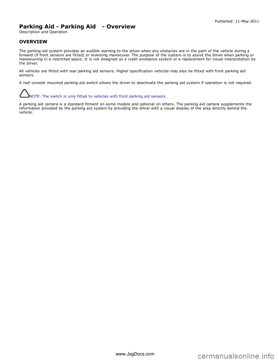
Parking Aid - Parking Aid - Overview
Description and Operation
OVERVIEW Published: 11-May-2011
The parking aid system provides an audible warning to the driver when any obstacles are in the path of the vehicle during a
forward (if front sensors are fitted) or reversing manoeuver. The purpose of the system is to assist the driver when parking or
manoeuvring in a restricted space. It is not designed as a crash avoidance system or a replacement for visual interpretation by
the driver.
All vehicles are fitted with rear parking aid sensors. Higher specification vehicles may also be fitted with front parking aid
sensors.
A roof console mounted parking aid switch allows the driver to deactivate the parking aid system if operation is not required.
NOTE: The switch is only fitted to vehicles with front parking aid sensors.
A parking aid camera is a standard fitment on some models and optional on others. The parking aid camera supplements the
information provided by the parking aid system by providing the driver with a visual display of the area directly behind the
vehicle.
www.JagDocs.com
Page 1938 of 3039
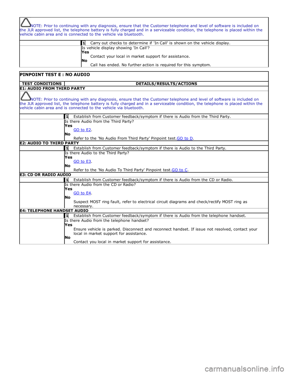
NOTE: Prior to continuing with any diagnosis, ensure that the Customer telephone and level of software is included on
the JLR approved list, the telephone battery is fully charged and in a serviceable condition, the telephone is placed within the
vehicle cabin area and is connected to the vehicle via bluetooth. 1 Carry out checks to determine if 'In Call' is shown on the vehicle display. Is vehicle display showing 'In Call'?
Yes
Contact your local in market support for assistance.
No
Call has ended. No further action is required for this symptom.
PINPOINT TEST E : NO AUDIO TEST CONDITIONS DETAILS/RESULTS/ACTIONS E1: AUDIO FROM THIRD PARTY
NOTE: Prior to continuing with any diagnosis, ensure that the Customer telephone and level of software is included on
the JLR approved list, the telephone battery is fully charged and in a serviceable condition, the telephone is placed within the
vehicle cabin area and is connected to the vehicle via bluetooth. 1 Establish from Customer feedback/symptom if there is Audio from the Third Party. Is there Audio from the Third Party? Yes
GO to E2. No
Refer to the 'No Audio From Third Party' Pinpoint test.GO to D. E2: AUDIO TO THIRD PARTY 1 Establish from Customer feedback/symptom if there is Audio to the Third Party. Is there Audio to the Third Party? Yes
GO to E3. No
Refer to the 'No Audio To Third Party' Pinpoint test.GO to C. E3: CD OR RADIO AUDIO 1 Establish from Customer feedback/symptom if there is Audio from the CD or Radio. Is there Audio from the CD or Radio? Yes
GO to E4. No
Suspect MOST ring fault, refer to electrical circuit diagrams and check/rectify MOST ring as necessary. E4: TELEPHONE HANDSET AUDIO 1 Establish from Customer feedback/symptom if there is Audio from the telephone handset. Is there Audio from the telephone handset? Yes
Ensure vehicle is parked. Disconnect and reconnect handset. If issue not resolved, contact your
local in market support for assistance.
No
Contact you local in market support for assistance.
Page 2034 of 3039
dependant on a particular ignition mode status. The side lamps will also be illuminated when the lighting control switch is in
the AUTO position and a 'lights on' signal is received by the CJB from the rain/light sensor Side Marker Lamps (NAS only)
The side marker lamp is located in the outer part of the headlamp assembly. The side marker lamp uses a W5W wedge fitting
bulb. The bulb is fitted into a holder which connects with contacts in the headlamp housing. The holder is fitted into an
aperture which connects with contacts in the headlamp housing. The side marker lamp is active at all times when the side
lamps are active.
AUTOMATIC HEADLAMP OPERATION
The automatic headlamp function is a driver assistance system. The driver can override the system operation by selection of
side lamp or headlamp on if the ambient light conditions require front and rear lighting to be active. The automatic headlamp
system uses a light sensor and the CJB, which are connected via a LIN (local interconnect network) bus to control the headlamp functionality. The light sensor is incorporated in the rain/light sensor located on the inside of the windshield, below
the rear view mirror. The wiper system also uses the rain/light sensor for automatic wiper operation.
The light sensor measures the ambient light around the vehicle in a vertical direction and also the angular light level from the
front of the vehicle. The rain/light sensor uses vehicle speed signals, wiper switch position and the park position of the front
wipers to control the system. The automatic headlamp operation uses ambient light levels which are monitored by photodiode
incorporated in the rain/light sensor. The rain/light sensor sends a lights on/off request to the CJB on the LIN bus, which responds by switching on the low beam headlamps, front side lamps and rear tail lamps. The automatic headlamps are
activated under the following conditions:
Twilight
Darkness
Rain
Snow
Tunnels
Underground or multistoried car parks.
Operation of the automatic headlamps requires the ignition to be in ignition mode 6, the lighting control switch to be in the
'AUTO' position and a lights on request signal from the light sensor. If the rain sensor signal activates the fast speed wipers,
the low beam headlamps are activated, providing the lighting control switch is in the 'AUTO' position.
HEADLAMP LEVELING
Headlamp leveling provides for the adjustment of the vertical aim of the headlamps. The leveling system is primarily required
to minimise glare to other road users when a heavy load is in the rear of the vehicle. Two systems of headlamp leveling are
available; manual and static dynamic.
Manual Headlamp Leveling
The manual system uses a thumbwheel rheostat to adjust the vertical alignment of the headlamps to compensate for differing
vehicle loading. The rotary thumbwheel is located on the auxiliary lighting switch, adjacent to the illumination dimmer
thumbwheel. Three positions are available to adjust the headlamps to a position to prevent glare to other road users.
Static Dynamic Headlamp Leveling
The static dynamic headlamp leveling system uses the following components:
Front and rear vehicle height sensors
Two headlamp leveling, vertical adjustment motors
Headlamp leveling module
Ignition in mode 6
Vehicle speed information from ABS module.
The static dynamic system uses height sensors fitted to the front and rear suspension and a headlamp leveling module which
periodically monitors the vehicle attitude and adjusts the headlamp vertical alignment accordingly.
Static dynamic headlamp leveling is controlled by a headlamp leveling module located in the lower instrument panel, behind
the glovebox.
The height sensors are both located on the RH side of the vehicle. The front sensor is attached to the front suspension lower arm with a strap and to the front sub frame with a bracket and 2 bolts. The rear sensor is attached to the rear suspension
upper control arm with a cable tied clip and to the rear sub frame with a bracket and 2 bolts. Each sensor has 3 connections to
the headlamp leveling module; power, ground and signal.
DAYTIME RUNNING LAMPS (DRL)
Refer to DRL section for details. Refer to: Daytime Running Lamps (DRL) (417-04 Daytime Running Lamps (DRL), Description and Operation).
REAR LAMP ASSEMBLY
The rear lamp assembly is a 2 piece unit, with one part located in the rear quarter panel and the second part attached to the
luggage compartment lid. The outer rear lamp assembly is located in a recess in the vehicle body. The lamp is secured with 2
studs inboard studs on the lamp body which are secured to the vehicle body with 2 nuts. A third outboard stud and nut secures
Page 2100 of 3039

DTC Description Possible Causes Action B1D3523 Hazard Switch
Hazard warning lamp
switch digital input circuit
- signal stuck low Carry out any pinpoint test associated with this DTC using the
manufacturer approved diagnostic system. Refer to the electrical
circuit diagrams and check hazard warning lamp switch digital
input circuit for short to ground U001988
Low Speed CAN
Communication
Bus
Bus off Carry out any pinpoint test associated with this DTC using the
manufacturer approved diagnostic system U014000
Lost
Communication
With Body
Control Module
No sub type information Carry out any pinpoint test associated with this DTC using the
manufacturer approved diagnostic system U015500
Lost
Communication
With Instrument
Panel Cluster
(IPC) Control
Module
No sub type information Carry out any pinpoint test associated with this DTC using the
manufacturer approved diagnostic system U015900
Lost
Communication
With Parking
Assist Control
Module "A"
No sub type information Carry out any pinpoint test associated with this DTC using the
manufacturer approved diagnostic system U016400
Lost
Communication
With HVAC
Control Module
No sub type information Carry out any pinpoint test associated with this DTC using the
manufacturer approved diagnostic system U021400
Lost
Communication
With Remote
Function
Actuation
No sub type information Carry out any pinpoint test associated with this DTC using the
manufacturer approved diagnostic system U030046
Internal Control
Module Software
Incompatibility
Calibration/parameter
memory failure Suspect the RJB. Check and install a new RJB as required, refer
to the new module/component installation note at the top of the
DTC Index U100000
Solid State Driver
Protection Active
-Driver Disabled
No sub type information Carry out any pinpoint test associated with this DTC using the
manufacturer approved diagnostic system U1A1449
CAN Initialisation
Failure
Internal electronic failure Suspect the RJB. Check and install a new RJB as required, refer
to the new module/component installation note at the top of the
DTC Index U300049 Control Module
Internal electronic failure Suspect the RJB. Check and install a new RJB as required, refer
to the new module/component installation note at the top of the
DTC Index U300055 Control Module
Not configured Re-configure the RJB using the manufacturer approved diagnostic
system www.JagDocs.com