2010 JAGUAR XFR auxiliary battery
[x] Cancel search: auxiliary batteryPage 2013 of 3039
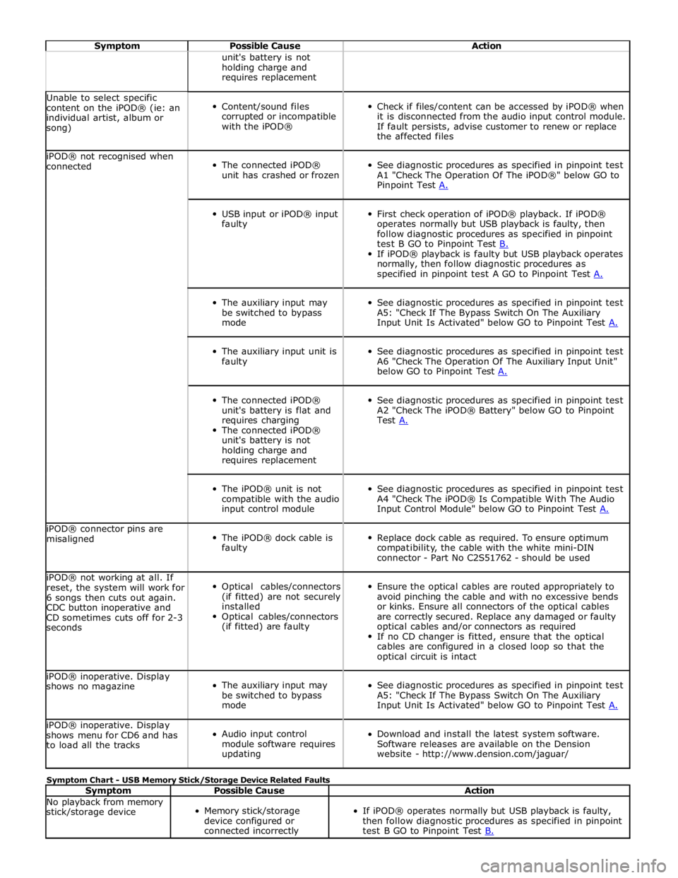
Symptom Possible Cause Action unit's battery is not
holding charge and
requires replacement Unable to select specific
content on the iPOD® (ie: an
individual artist, album or
song)
Content/sound files
corrupted or incompatible
with the iPOD®
Check if files/content can be accessed by iPOD® when
it is disconnected from the audio input control module.
If fault persists, advise customer to renew or replace
the affected files iPOD® not recognised when
connected
The connected iPOD®
unit has crashed or frozen
See diagnostic procedures as specified in pinpoint test
A1 "Check The Operation Of The iPOD®" below GO to
Pinpoint Test A.
USB input or iPOD® input
faulty
First check operation of iPOD® playback. If iPOD®
operates normally but USB playback is faulty, then
follow diagnostic procedures as specified in pinpoint
test B GO to Pinpoint Test B. If iPOD® playback is faulty but USB playback operates
normally, then follow diagnostic procedures as
specified in pinpoint test A GO to Pinpoint Test A.
The auxiliary input may
be switched to bypass
mode
See diagnostic procedures as specified in pinpoint test
A5: "Check If The Bypass Switch On The Auxiliary
Input Unit Is Activated" below GO to Pinpoint Test A.
The auxiliary input unit is
faulty
See diagnostic procedures as specified in pinpoint test
A6 "Check The Operation Of The Auxiliary Input Unit"
below GO to Pinpoint Test A.
The connected iPOD®
unit's battery is flat and
requires charging
The connected iPOD®
unit's battery is not
holding charge and
requires replacement
See diagnostic procedures as specified in pinpoint test
A2 "Check The iPOD® Battery" below GO to Pinpoint
Test A.
The iPOD® unit is not
compatible with the audio
input control module
See diagnostic procedures as specified in pinpoint test
A4 "Check The iPOD® Is Compatible With The Audio
Input Control Module" below GO to Pinpoint Test A. iPOD® connector pins are
misaligned
The iPOD® dock cable is
faulty
Replace dock cable as required. To ensure optimum
compatibility, the cable with the white mini-DIN
connector - Part No C2S51762 - should be used iPOD® not working at all. If
reset, the system will work for
6 songs then cuts out again.
CDC button inoperative and
CD sometimes cuts off for 2-3
seconds
Optical cables/connectors
(if fitted) are not securely
installed
Optical cables/connectors
(if fitted) are faulty
Ensure the optical cables are routed appropriately to
avoid pinching the cable and with no excessive bends
or kinks. Ensure all connectors of the optical cables
are correctly secured. Replace any damaged or faulty
optical cables and/or connectors as required
If no CD changer is fitted, ensure that the optical
cables are configured in a closed loop so that the
optical circuit is intact iPOD® inoperative. Display
shows no magazine
The auxiliary input may
be switched to bypass
mode
See diagnostic procedures as specified in pinpoint test
A5: "Check If The Bypass Switch On The Auxiliary
Input Unit Is Activated" below GO to Pinpoint Test A. iPOD® inoperative. Display
shows menu for CD6 and has
to load all the tracks
Audio input control
module software requires
updating
Download and install the latest system software.
Software releases are available on the Dension
website - http://www.dension.com/jaguar/ Symptom Chart - USB Memory Stick/Storage Device Related Faults
Symptom Possible Cause Action No playback from memory
stick/storage device
Memory stick/storage
device configured or
connected incorrectly
If iPOD® operates normally but USB playback is faulty,
then follow diagnostic procedures as specified in pinpoint
test B GO to Pinpoint Test B.
Page 2014 of 3039
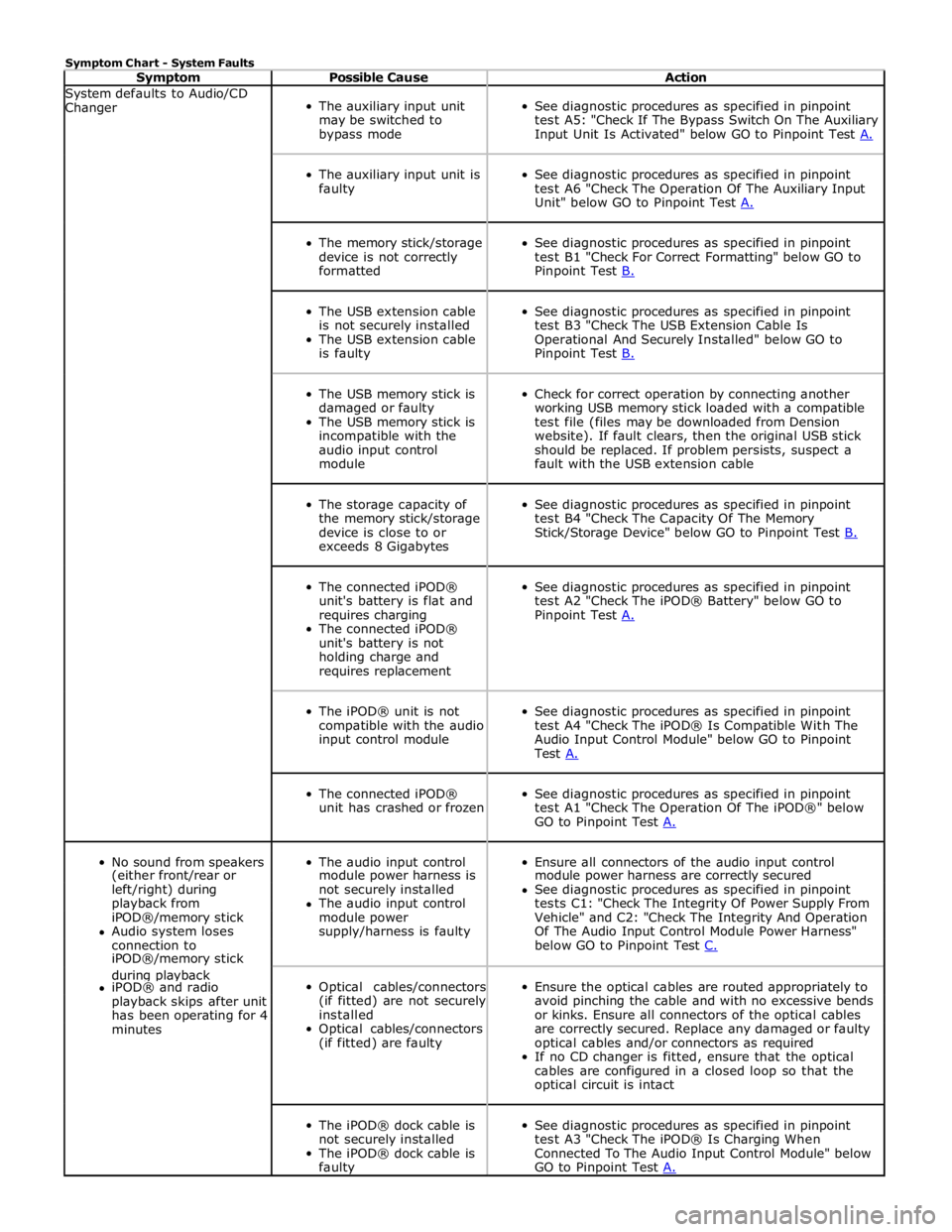
Symptom Chart - System Faults
Symptom Possible Cause Action System defaults to Audio/CD
Changer
The auxiliary input unit
may be switched to
bypass mode
See diagnostic procedures as specified in pinpoint
test A5: "Check If The Bypass Switch On The Auxiliary
Input Unit Is Activated" below GO to Pinpoint Test A.
The auxiliary input unit is
faulty
See diagnostic procedures as specified in pinpoint
test A6 "Check The Operation Of The Auxiliary Input
Unit" below GO to Pinpoint Test A.
The memory stick/storage
device is not correctly
formatted
See diagnostic procedures as specified in pinpoint
test B1 "Check For Correct Formatting" below GO to
Pinpoint Test B.
The USB extension cable
is not securely installed
The USB extension cable
is faulty
See diagnostic procedures as specified in pinpoint
test B3 "Check The USB Extension Cable Is
Operational And Securely Installed" below GO to
Pinpoint Test B.
The USB memory stick is
damaged or faulty
The USB memory stick is
incompatible with the
audio input control
module
Check for correct operation by connecting another
working USB memory stick loaded with a compatible
test file (files may be downloaded from Dension
website). If fault clears, then the original USB stick
should be replaced. If problem persists, suspect a
fault with the USB extension cable
The storage capacity of
the memory stick/storage
device is close to or
exceeds 8 Gigabytes
See diagnostic procedures as specified in pinpoint
test B4 "Check The Capacity Of The Memory
Stick/Storage Device" below GO to Pinpoint Test B.
The connected iPOD®
unit's battery is flat and
requires charging
The connected iPOD®
unit's battery is not
holding charge and
requires replacement
See diagnostic procedures as specified in pinpoint
test A2 "Check The iPOD® Battery" below GO to
Pinpoint Test A.
The iPOD® unit is not
compatible with the audio
input control module
See diagnostic procedures as specified in pinpoint
test A4 "Check The iPOD® Is Compatible With The
Audio Input Control Module" below GO to Pinpoint
Test A.
The connected iPOD®
unit has crashed or frozen
See diagnostic procedures as specified in pinpoint
test A1 "Check The Operation Of The iPOD®" below
GO to Pinpoint Test A.
No sound from speakers
The audio input control
Ensure all connectors of the audio input control (either front/rear or module power harness is module power harness are correctly secured left/right) during not securely installed See diagnostic procedures as specified in pinpoint playback from The audio input control tests C1: "Check The Integrity Of Power Supply From iPOD®/memory stick module power Vehicle" and C2: "Check The Integrity And Operation Audio system loses supply/harness is faulty Of The Audio Input Control Module Power Harness" connection to below GO to Pinpoint Test C. iPOD®/memory stick during playback
Optical cables/connectors
(if fitted) are not securely
installed
Optical cables/connectors
(if fitted) are faulty
Ensure the optical cables are routed appropriately to
avoid pinching the cable and with no excessive bends
or kinks. Ensure all connectors of the optical cables
are correctly secured. Replace any damaged or faulty
optical cables and/or connectors as required
If no CD changer is fitted, ensure that the optical
cables are configured in a closed loop so that the
optical circuit is intact iPOD® and radio playback skips after unit has been operating for 4 minutes
The iPOD® dock cable is
not securely installed
The iPOD® dock cable is
faulty
See diagnostic procedures as specified in pinpoint
test A3 "Check The iPOD® Is Charging When
Connected To The Audio Input Control Module" below
GO to Pinpoint Test A.
Page 2017 of 3039
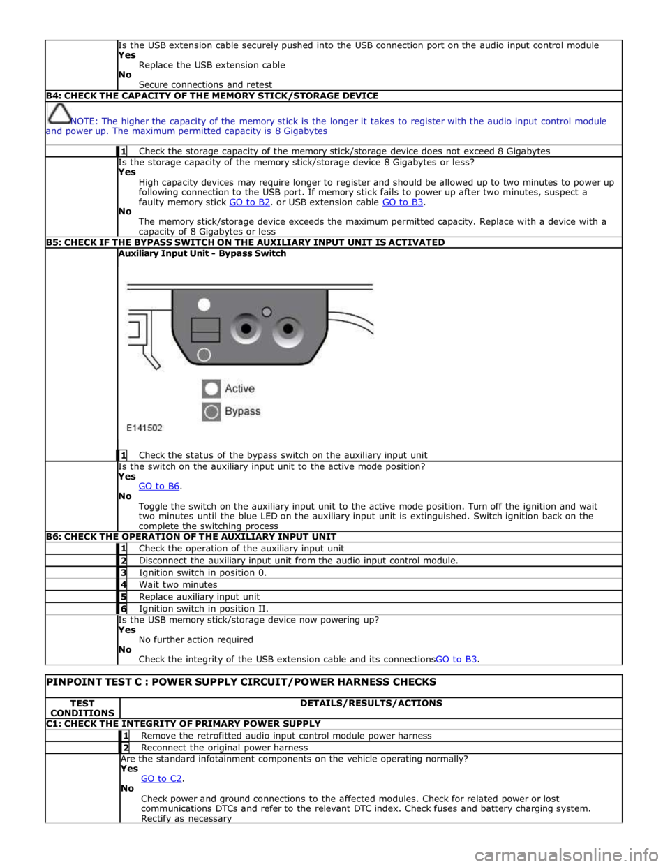
Is the USB extension cable securely pushed into the USB connection port on the audio input control module
Yes
Replace the USB extension cable
No
Secure connections and retest B4: CHECK THE CAPACITY OF THE MEMORY STICK/STORAGE DEVICE
NOTE: The higher the capacity of the memory stick is the longer it takes to register with the audio input control module
and power up. The maximum permitted capacity is 8 Gigabytes 1 Check the storage capacity of the memory stick/storage device does not exceed 8 Gigabytes Is the storage capacity of the memory stick/storage device 8 Gigabytes or less?
Yes
High capacity devices may require longer to register and should be allowed up to two minutes to power up
following connection to the USB port. If memory stick fails to power up after two minutes, suspect a
faulty memory stick GO to B2. or USB extension cable GO to B3. No
The memory stick/storage device exceeds the maximum permitted capacity. Replace with a device with a capacity of 8 Gigabytes or less B5: CHECK IF THE BYPASS SWITCH ON THE AUXILIARY INPUT UNIT IS ACTIVATED Auxiliary Input Unit - Bypass Switch
1 Check the status of the bypass switch on the auxiliary input unit Is the switch on the auxiliary input unit to the active mode position?
Yes
GO to B6. No
Toggle the switch on the auxiliary input unit to the active mode position. Turn off the ignition and wait
two minutes until the blue LED on the auxiliary input unit is extinguished. Switch ignition back on the complete the switching process B6: CHECK THE OPERATION OF THE AUXILIARY INPUT UNIT 1 Check the operation of the auxiliary input unit 2 Disconnect the auxiliary input unit from the audio input control module. 3 Ignition switch in position 0. 4 Wait two minutes 5 Replace auxiliary input unit 6 Ignition switch in position II. Is the USB memory stick/storage device now powering up?
Yes
No further action required
No
Check the integrity of the USB extension cable and its connectionsGO to B3.
PINPOINT TEST C : POWER SUPPLY CIRCUIT/POWER HARNESS CHECKS TEST
CONDITIONS DETAILS/RESULTS/ACTIONS C1: CHECK THE INTEGRITY OF PRIMARY POWER SUPPLY 1 Remove the retrofitted audio input control module power harness 2 Reconnect the original power harness Are the standard infotainment components on the vehicle operating normally?
Yes
GO to C2. No
Check power and ground connections to the affected modules. Check for related power or lost
communications DTCs and refer to the relevant DTC index. Check fuses and battery charging system. Rectify as necessary
Page 2024 of 3039
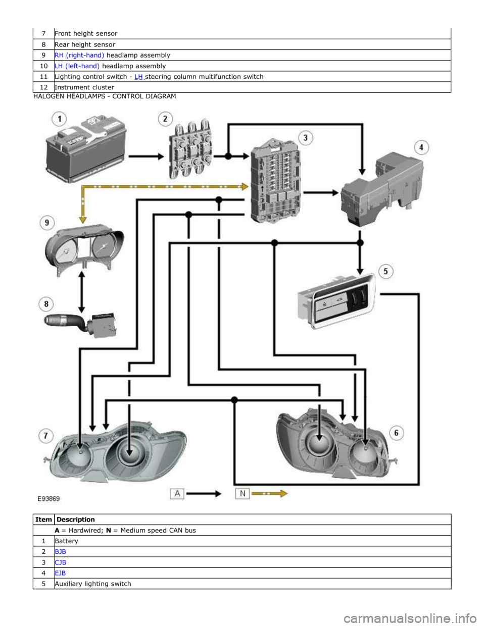
8 Rear height sensor 9 RH (right-hand) headlamp assembly 10 LH (left-hand) headlamp assembly 11 Lighting control switch - LH steering column multifunction switch 12 Instrument cluster HALOGEN HEADLAMPS - CONTROL DIAGRAM
Item Description A = Hardwired; N = Medium speed CAN bus 1 Battery 2 BJB 3 CJB 4 EJB 5 Auxiliary lighting switch
Page 2101 of 3039
Published: 11-May-2011
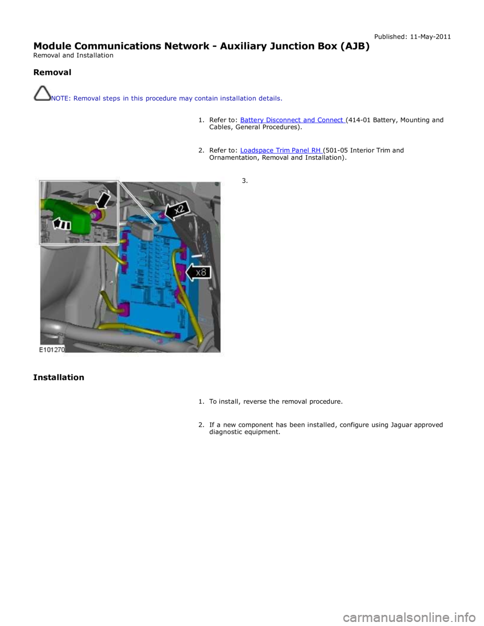
Module Communications Network - Auxiliary Junction Box (AJB)
Removal and Installation
Removal
NOTE: Removal steps in this procedure may contain installation details.
1. Refer to: Battery Disconnect and Connect (414-01 Battery, Mounting and Cables, General Procedures).
2. Refer to: Loadspace Trim Panel RH (501-05 Interior Trim and Ornamentation, Removal and Installation).
3.
Installation
1. To install, reverse the removal procedure.
2. If a new component has been installed, configure using Jaguar approved
diagnostic equipment.
Page 2172 of 3039
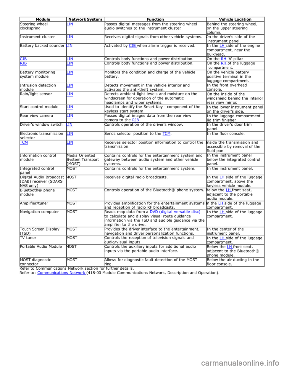
Module Network System Function Vehicle Location
Steering wheel
clockspring LIN Passes digital messages from the steering wheel
audio switches to the instrument cluster. Behind the steering wheel,
on the upper steering
column.
Instrument cluster LIN Receives digital signals from other vehicle systems. On the driver's side of the
instrument panel.
Battery backed sounder LIN Activated by CJB when alarm trigger is received. In the LH side of the engine compartment, near the
bulkhead.
CJB LIN Controls body functions and power distribution. On the RH 'A' pillar.
RJB LIN Controls body functions and power distribution. On the RH of the luggage compartment.
Battery monitoring
system module
Intrusion detection
module LIN Monitors the condition and charge of the vehicle
battery.
LIN Detects movement in the vehicle interior and
activates the anti-theft system. On the vehicle battery
positive terminal in the
luggage compartment.
In the front overhead
console.
Rain/light sensor LIN Detects ambient light levels and moisture on the
windscreen for operation of the automatic
headlamps and wiper systems.
Start control module LIN Used to identify the Smart Key - component of the
keyless start system.
Rear view camera LIN Passes digital images data from the rear view
camera to the RJB On the inside of the
windshield behind the interior
rear view mirror.
In the lower instrument panel
on the driver's side.
In the luggage compartment
lid trim finisher.
Driver's window switch LIN Controls operation of the driver's window. In the driver's door trim
panel.
Electronic transmission
selector LIN Sends selector position to the TCM. In the floor console. TCM LIN Receives selector position information to control the Inside the transmission and
Information control
module
Media Oriented
System Transport
(MOST) transmission.
Contains controls for the entertainment system and
gateway between audio system and other vehicle
systems. accessible by removal of the
fluid pan.
In the instrument panel
below the integrated control
panel.
Integrated control
panel MOST Contains controls for the entertainment system. In the instrument panel.
Digital Audio Broadcast MOST Receives digital radio broadcasts. In the LH side of the luggage (DAB) receiver (SDARS
NAS only)
Bluetooth® phone
module compartment, above the
keyless vehicle module.
MOST Controls operation of the Bluetooth® phone system. Below the LH front seat, adjacent to the portable
audio module.
Amplifier/tuner MOST Provides amplification for the entertainment systems In the LH side of the luggage and reception of radio RF broadcasts.
Navigation computer MOST Reads map data from a DVD (digital versatile disc)
to calculate and display visual route guidance
information via the TSD and audible guidance via the
amplifier to the driver. compartment.
In the LH side of the luggage compartment.
Touch Screen Display
(TSD) MOST Provides the driver interface to the entertainment,
navigation and driver personalization functions. In the center of the
instrument panel.
TV tuner MOST Controls the reception of television signals and
audio/visual inputs.
Portable Audio Module MOST Controls the auxiliary inputs for additional audio
inputs via the portable audio interface. In the LH side of the luggage compartment.
Below the LH front seat, adjacent to the Bluetooth®
phone module.
MOST diagnostic
connector MOST Allows for diagnostic fault detection of the MOST
ring. Below the air ducting in the
floor console.
Refer to Communications Network section for further details.
Refer to: Communications Network (418-00 Module Communications Network, Description and Operation).
Page 2177 of 3039

DTC Description Possible Cause Action C1B1415 Sensor Supply #1
Window position hall sensors
supply circuit - short to power,
open circuit Carry out any pinpoint tests associated with this DTC
using the manufacturer approved diagnostic system.
Refer to the electrical circuit diagrams and test window
position hall sensors supply circuit for short to power, open circuit C1B1511 Sensor Supply #2
Hall sensor supply circuit - short
to ground Refer to the electrical circuit diagrams and test window
position hall sensors supply circuit for short to ground C1B1515 Sensor Supply #2
Hall sensor supply circuit - short
to power, open circuit Carry out any pinpoint tests associated with this DTC
using the manufacturer approved diagnostic system.
Refer to the electrical circuit diagrams and test window
position hall sensors supply circuit for short to power, open circuit U001000
Medium Speed CAN
Communication Bus
Bus off Carry out any pinpoint tests associated with this DTC
using the manufacturer approved diagnostic system U014000
Lost Communication
With Body Control
Module
Missing message from CJB Carry out any pinpoint tests associated with this DTC
using the manufacturer approved diagnostic system U020800
Lost Communication
With Seat Control
Module "A"
Missing message from driver
seat module Carry out any pinpoint tests associated with this DTC
using the manufacturer approved diagnostic system U030000
Internal Control
Module Software
Incompatibility
Invalid configuration message is
received Re-configure the RJB using the manufacturer approved
diagnostic system. Clear the DTC and retest. If the DTC
remains suspect the DDM. Check and install a new
module as required, refer to the new module/component
installation note at the top of the DTC Index U200224 Switch
Signal stuck high Clear DTC and re-test. If DTC remains, suspect the
passenger side window switch. Check and install a new passenger side window switch U200424
Auxiliary Switch
Pack
Left or right rear door local
switch - signal stuck high Check for stuck rear window switch. Refer to the
electrical circuit diagrams and check left or right rear
door local switch circuit for short circuit U201011 Switch illumination
Rear window switch illumination
circuit - short to ground Refer to the electrical circuit diagrams and check rear
window switch illumination circuit for short to ground U201208
Car Configuration
Parameter(s)
Bus signal/message failures Cycle the ignition status and re-test. If DTC remains,
re-configure the RJB using the manufacturer approved diagnostic system U201324 Switch Pack
Signal stuck high Clear DTC and re-test. If DTC remains, install a new
driver door switch pack U201444
Control Module
Hardware
Data memory failure Suspect the DDM. Check and install a new DDM as
required, refer to the new module/component
installation note at the top of the DTC Index U210000
Initial Configuration
Not Complete
No sub type information Re-configure the DDM using the manufacturer approved
diagnostic system U300049 Control Module
Internal electronic failure Suspect the DDM. Check and install a new DDM as
required, refer to the new module/component
installation note at the top of the DTC Index U300255
Vehicle
Identification
Number
Not configured Re-configure the DDM as new using the manufacturer
approved diagnostic system and re-test. If DTC remains
install a new module, refer to the new
module/component installation note at the top of the
DTC Index U300281
Vehicle
Identification
Number (VIN)
Vehicle/component mis-match.
Corrupt VIN data being
transmitted, module previously
installed to other vehicle Check and install correct/new module as required, refer
to the new module/component installation note at the
top of the DTC Index U300362 Battery voltage
Mis-match in battery voltage, of
2 volts or more, between DDM
and RJB Carry out any pinpoint tests associated with this DTC
using the manufacturer approved diagnostic system
Page 2186 of 3039

DTC Description Possible Cause Action C1B1415 Sensor Supply #1
Front window position hall
sensor supply circuit - short to
power, open circuit Carry out any pinpoint tests associated with this DTC
using the manufacturer approved diagnostic system.
Refer to the electrical circuit diagrams and test front
window position hall sensor supply circuit for short to power, open circuit C1B1511 Sensor Supply #2
Hall sensor supply circuit - short
to ground Refer to the electrical circuit diagrams and test window
position hall sensors supply circuit for short to ground C1B1515 Sensor Supply #2
Hall sensor supply circuit - short
to power, open circuit Carry out any pinpoint tests associated with this DTC
using the manufacturer approved diagnostic system.
Refer to the electrical circuit diagrams and test window
position hall sensors supply circuit for short to power, open circuit U001000
Medium Speed CAN
Communication Bus
Bus off Carry out any pinpoint tests associated with this DTC
using the manufacturer approved diagnostic system U014000
Lost Communication
With Body Control
Module
Missing message from CJB Carry out any pinpoint tests associated with this DTC
using the manufacturer approved diagnostic system U020800
Lost Communication
With Seat Control
Module "A"
Missing message from driver
seat module Carry out any pinpoint tests associated with this DTC
using the manufacturer approved diagnostic system U030000
Internal Control
Module Software
Incompatibility
Invalid configuration message is
received Re-configure the RJB using the manufacturer approved
diagnostic system. Clear the DTC and retest. If the DTC
remains suspect the PDM. Check and install a new
module as required, refer to the new module/component
installation note at the top of the DTC Index U200224 Switch
Signal stuck high Clear DTC and re-test. If DTC remains, suspect the
passenger side window switch. Check and install a new passenger side window switch U200424
Auxiliary Switch
Pack
Left or right rear door local
switch - signal stuck high Check for stuck rear window switch. Refer to the
electrical circuit diagrams and check left or right rear
door local switch circuit for short circuit U201011 Switch illumination
Rear window switch illumination
circuit - short to ground Refer to the electrical circuit diagrams and check rear
window switch illumination circuit for short to ground U201208
Car Configuration
Parameter(s)
Bus signal/message failures Cycle the ignition status and re-test. If DTC remains,
re-configure the RJB using the manufacturer approved diagnostic system U201324 Switch Pack
Signal stuck high Clear DTC and re-test. If DTC remains, install a new
driver door switch pack U201444
Control Module
Hardware
Data memory failure Suspect the PDM. Check and install a new PDM as
required, refer to the new module/component
installation note at the top of the DTC Index U210000
Initial Configuration
Not Complete
No sub type information Re-configure the PDM using the manufacturer approved
diagnostic system U300049 Control Module
Internal electronic failure Suspect the PDM. Check and install a new PDM as
required, refer to the new module/component
installation note at the top of the DTC Index U300255
Vehicle
Identification
Number
Not configured Re-configure the PDM as new using the manufacturer
approved diagnostic system and re-test. If DTC remains
install a new module, refer to the new
module/component installation note at the top of the
DTC Index U300281
Vehicle
Identification
Number (VIN)
Vehicle/component mis-match.
Corrupt VIN data being
transmitted, module previously
installed to other vehicle Check and install correct/new module as required, refer
to the new module/component installation note at the
top of the DTC Index U300362 Battery voltage
Mis-match in battery voltage, of
2 volts or more, between PDM
and RJB Carry out any pinpoint tests associated with this DTC
using the manufacturer approved diagnostic system