2010 JAGUAR XFR auxiliary battery
[x] Cancel search: auxiliary batteryPage 1708 of 3039
Published: 11-May-2011
Climate Control - Control Components - System Operation and Component Description
Description and Operation
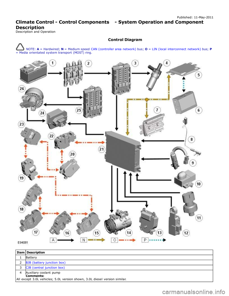
Control Diagram
NOTE: A = Hardwired; N = Medium speed CAN (controller area network) bus; O = LIN (local interconnect network) bus; P
= Media orientated system transport (MOST) ring.
Item Description 1 Battery 2 BJB (battery junction box) 3 CJB (central junction box) 4 Auxiliary coolant pump Comments:
All except 3.0L vehicles; 5.0L version shown, 3.0L diesel version similar.
Page 1766 of 3039
Published: 11-May-2011
Auxiliary Climate Control - Electric Booster Heater - System Operation and
Component Description
Description and Operation
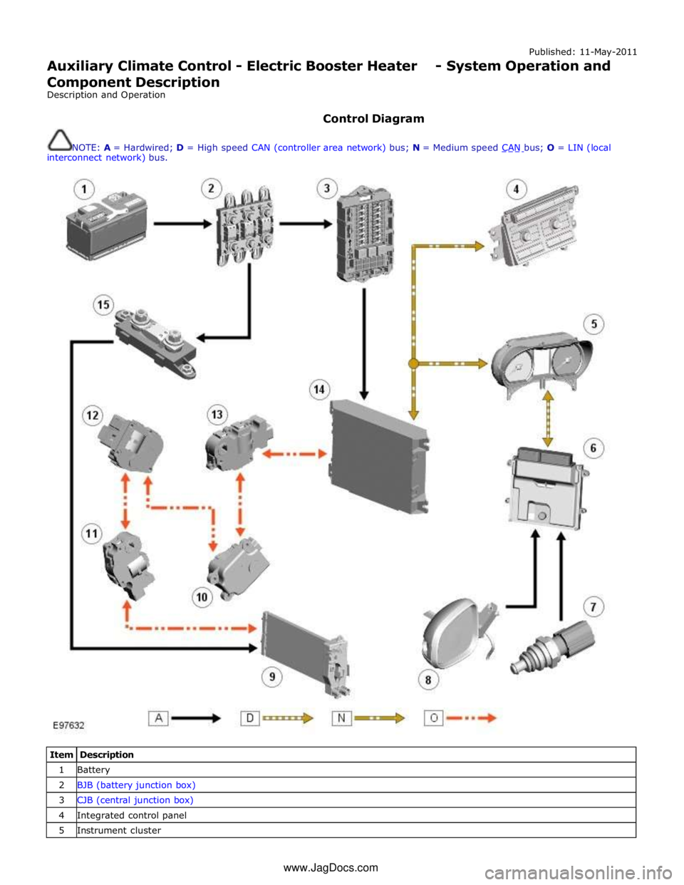
Control Diagram
NOTE: A = Hardwired; D = High speed CAN (controller area network) bus; N = Medium speed CAN bus; O = LIN (local interconnect network) bus.
Item Description 1 Battery 2 BJB (battery junction box) 3 CJB (central junction box) 4 Integrated control panel 5 Instrument cluster www.JagDocs.com
Page 1772 of 3039
Auxiliary Climate Control - Electric Booster Heater
Removal and Installation
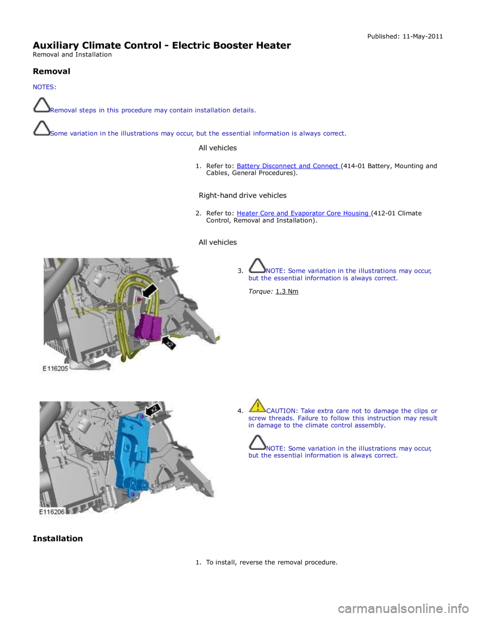
Removal
NOTES:
Removal steps in this procedure may contain installation details.
Some variation in the illustrations may occur, but the essential information is always correct.
All vehicles Published: 11-May-2011
1. Refer to: Battery Disconnect and Connect (414-01 Battery, Mounting and Cables, General Procedures).
Right-hand drive vehicles
2. Refer to: Heater Core and Evaporator Core Housing (412-01 Climate Control, Removal and Installation).
All vehicles
Installation
3. NOTE: Some variation in the illustrations may occur,
but the essential information is always correct.
Torque: 1.3 Nm
4. CAUTION: Take extra care not to damage the clips or
screw threads. Failure to follow this instruction may result
in damage to the climate control assembly.
NOTE: Some variation in the illustrations may occur,
but the essential information is always correct.
1. To install, reverse the removal procedure.
Page 1787 of 3039
the RCM and illuminated by the instrument cluster on receipt of high speed CAN bus messages. The safety belt warning indicator is not subject to the 3 second indicator check when the ignition is switched on.
The operation of the passenger seat buckle switch is as described below with the exception that the instrument cluster must
receive a hardwired signal from the belt minder control module to indicate that a passenger is occupying the seat.
The safety belt warning indicator is subject to a timer. The warning indicator is activated when the following conditions exist:
Ignition is switched on
One of the front seat belts is unbuckled
USA market only - 75 seconds has elapsed after ignition on mode is selected
Vehicle is not in reverse gear
Vehicle speed is more than 8 km/h (5 mph).
Once the above parameters are met, the instrument cluster flashes the warning indicator at 2 Hz for 10 seconds accompanied
by a simultaneous chime. After 10 seconds the chime ceases and the warning indicator is permanently illuminated for 20
seconds. This sequence is repeated every 30 seconds until one of the following events occurs:
300 seconds has elapsed
The safety belt of the occupied front seats is fastened
The ignition is switched to off mode
The vehicle speed decreases to below 5 km/h (3 mph).
NOTE: On USA market vehicles, the warning indicator in not permanently illuminated.
The safety belt minder function cannot be disabled. The seat belt minder function can be disabled.
Refer to: Safety Belt System (501-20A Safety Belt System, Description and Operation). 14. Side Lamp Indicator
The instrument cluster controls the green colored side lamp indicator on receipt of a side lamp status message on the medium
speed CAN bus from the CJB and the auxiliary junction box. The lighting switch on the LH steering column multifunction switch is connected to the instrument cluster. Selections using this switch are detected by the cluster which requests the side or
headlamp operation via a message to the CJB and the RJB. The CJB and the RJB responds with a side lamp active message and the cluster illuminates the side lamp indicator. The side lamp indicator is not subject to the 3 second indicator check when
the ignition is switched on.
15. High Beam Indicator
The instrument cluster controls the blue colored high beam indicator on receipt of a high beam status message on the medium
speed CAN bus from the CJB. The lighting switch on the LH steering column multifunction switch is connected to the instrument cluster. High beam or flash selections using this switch are detected by the cluster which requests the light
operation via a CAN message to the CJB. The CJB responds with a high beam active message and the cluster illuminates the high beam indicator. The high beam indicator is not subject to the 3 second indicator check when the ignition is switched on.
16. Rear Fog Lamp Indicator
The amber colored rear fog lamp indicator is controlled by the auxiliary junction box and illuminated by the instrument cluster
on receipt of a rear fog lamp on message on the medium speed CAN bus from the RJB. The indicator is illuminated for as long as the rear fog lamps are active. The rear fog lamp indicator is not subject to the 3 second indicator check when the ignition is
switched on.
SPEEDOMETER
The speedometer is driven by high speed CAN signals transmitted by the ABS module. The wheel speeds are measured by sensors reading the rotational speed of the rear wheels from toothed targets on the hubs. An average of the two wheel speeds
are passed from the sensors to the ABS module in the form of pulsed signals. The ABS module converts these signals into a speed output on the high speed CAN to the instrument cluster. The same speed outputs from the wheel speed sensors are also used to calculate the distance the vehicle has travelled.
TACHOMETER
The tachometer is driven by an engine speed signal transmitted on the high speed CAN from the ECM. The signal is derived from the CKP (crankshaft position) sensor. The signal is received by the instrument cluster microprocessor and the output from
the microprocessor drives the tachometer.
FUEL GAGE
The fuel gage is controlled by CAN messages from the RJB. The RJB reads the values output by the fuel level sensors every 131 ms and transmits a fuel tank contents value, corrected for battery voltage, in a CAN message to the instrument cluster. A fuel pump symbol is displayed to the left of the linear gage. An arrow above the symbol shows the driver on which side of the
vehicle the fuel filler cap is located. Above the linear fuel gage, is a LCD (liquid crystal display) area which displays odometer
and trip readouts. When a trip computer function is selected, these are replaced by a trip computer display for the trip function
selected.
LIQUID CRYSTAL DISPLAY
In the area above and below the message center is a LCD display. The area below the message center displays a linear fuel www.JagDocs.com
Page 1795 of 3039
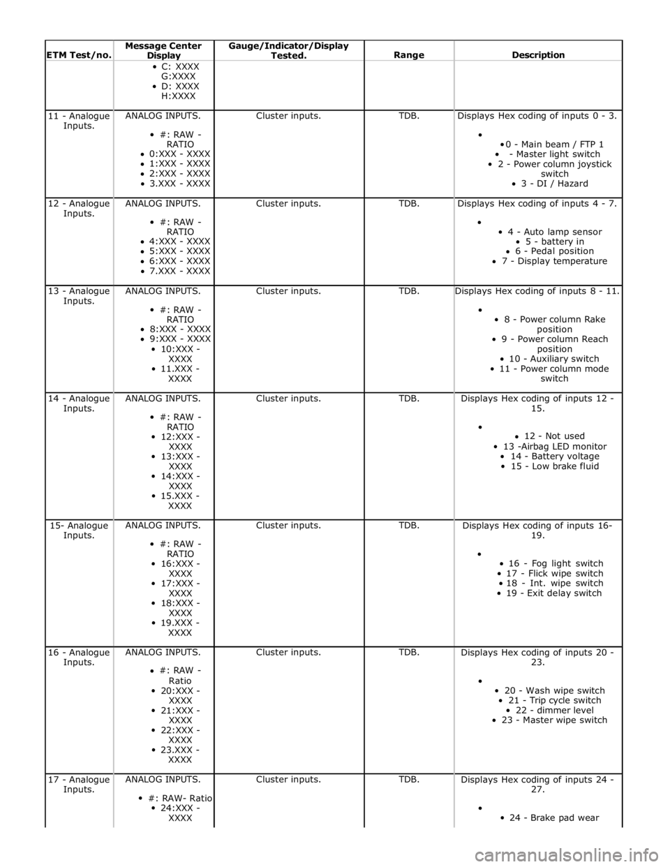
ETM Test/no. Message Center Display Gauge/Indicator/Display
Tested.
Range
Description C: XXXX
G:XXXX
D: XXXX
H:XXXX 11 - Analogue
Inputs. ANALOG INPUTS.
#: RAW -
RATIO
0:XXX - XXXX
1:XXX - XXXX
2:XXX - XXXX
3.XXX - XXXX Cluster inputs. TDB. Displays Hex coding of inputs 0 - 3.
0 - Main beam / FTP 1
- Master light switch
2 - Power column joystick
switch
3 - DI / Hazard 12 - Analogue
Inputs. ANALOG INPUTS.
#: RAW -
RATIO
4:XXX - XXXX
5:XXX - XXXX
6:XXX - XXXX
7.XXX - XXXX Cluster inputs. TDB. Displays Hex coding of inputs 4 - 7.
4 - Auto lamp sensor
5 - battery in
6 - Pedal position
7 - Display temperature 13 - Analogue
Inputs. ANALOG INPUTS.
#: RAW -
RATIO
8:XXX - XXXX
9:XXX - XXXX
10:XXX -
XXXX
11.XXX -
XXXX Cluster inputs. TDB. Displays Hex coding of inputs 8 - 11.
8 - Power column Rake
position
9 - Power column Reach
position
10 - Auxiliary switch
11 - Power column mode
switch 14 - Analogue
Inputs. ANALOG INPUTS.
#: RAW -
RATIO
12:XXX -
XXXX
13:XXX -
XXXX
14:XXX -
XXXX
15.XXX -
XXXX Cluster inputs. TDB.
Displays Hex coding of inputs 12 -
15.
12 - Not used
13 -Airbag LED monitor
14 - Battery voltage
15 - Low brake fluid 15- Analogue
Inputs. ANALOG INPUTS.
#: RAW -
RATIO
16:XXX -
XXXX
17:XXX -
XXXX
18:XXX -
XXXX
19.XXX -
XXXX Cluster inputs. TDB.
Displays Hex coding of inputs 16-
19.
16 - Fog light switch
17 - Flick wipe switch
18 - Int. wipe switch
19 - Exit delay switch 16 - Analogue
Inputs. ANALOG INPUTS.
#: RAW -
Ratio
20:XXX -
XXXX
21:XXX -
XXXX
22:XXX -
XXXX
23.XXX -
XXXX Cluster inputs. TDB.
Displays Hex coding of inputs 20 -
23.
20 - Wash wipe switch
21 - Trip cycle switch
22 - dimmer level
23 - Master wipe switch 17 - Analogue
Inputs. ANALOG INPUTS.
#: RAW- Ratio
24:XXX -
XXXX Cluster inputs. TDB.
Displays Hex coding of inputs 24 -
27.
24 - Brake pad wear
Page 1866 of 3039
Published: 07-Aug-2014
Battery and Charging System - General Information - Battery Care
Requirements
Description and Operation
1. INTRODUCTION
This document defines the requirements for care and maintenance of batteries, and the standard of battery care at dealers and
retailers for new vehicles.
This applies to all types of 12 Volt Lead Acid Batteries used in Jaguar and Land Rover vehicles whether they are conventional
flooded technology or Absorbed Glass Mat (AGM – also known as Valve Regulated Lead Acid (VRLA)) technology and also
applies to both Primary, Secondary and Auxiliary Batteries. AGM batteries offer improved resistance to cycling as seen in stop
start applications.
In order to prevent damage to the battery and ensure a satisfactory service life, all processes detailed within this document
must be rigorously adhered to.
It is equally important therefore to note the following key points:
All new vehicles leave the factory with either a transit relay installed and/or have a transit mode programmed into the
vehicle control modules. The transit relay must be removed and the transit mode disabled (where applicable) using an
approved diagnostic system, NOT MORE THAN 72 HOURS before the customer takes delivery.
The battery can be discharged by the following mechanisms:
- Self Discharge: - A lead acid battery will very slowly discharge itself due to its own internal chemical processes
whether it is connected to a vehicle or not.
- Quiescent Discharge: - The vehicle electrical systems when connected to the battery will draw charge from the
battery.
12 Volt Lead Acid Batteries rely on internal chemical processes to create a voltage and deliver current. These processes and
the internal chemical structure of the battery can be damaged if the battery is allowed to discharge over a number of weeks /
months, or is left in a discharged state for a lengthy time period.
On vehicles with conventional ignition keys, these must not be left in the ignition lock barrel when the transit relay
has been removed, otherwise quiescent current will increase and the battery will discharge more rapidly.
For keyless vehicles, the Smart Key must be stored at least 5m (16 ft) away from the vehicle when the vehicle is
parked or stored.
AGM Batteries are fully sealed and cannot have the electrolyte level topped up.
NOTE: Dealers and retailers involved in the storage / handling of vehicles and replacement batteries have a responsibility
to ensure that only a fully charged battery may be processed through the distribution selling chain.
2. GENERAL RULES FOR BATTERY CARE
2.1 Dealer Demonstration Vehicles
Vehicles used as dealer demonstrator(s), in a showroom, must be connected to a JLR approved showroom conditioner capable
of delivering 50 Amps. This will prevent the battery from being damaged.
2.2 Software Reflash, SDD work or Ignition On related workshop activities
Due to the high electrical current demand and high depth of discharge that can occur during vehicle software re-flash activities,
SDD work or ignition on (power mode 6) related work in the workshop, vehicles that are undergoing such activities MUST have a
JLR approved power supply capable of delivering 50 Amps or more.
2.3 Extended Vehicle Rework
For any extended vehicle rework that results in consuming vehicle power, either the battery should be disconnected or a JLR
approved power supply connected.
2.4 Jump Starting New vehicles before they have been delivered to the customer
It is the dealer / retailers responsibility to make sure the battery is not allowed to discharge by following the
instructions and processes defined in this manual.
However, if circumstances dictate that a new vehicle must be jump started due to a discharged battery whilst the
vehicle is in the dealer / retailers care, the battery on this vehicle must be replaced with a new one prior to delivery
to the customer at the dealer / retailers liability.
The vehicle should also undergo investigation as to why the battery became discharged.
Do not connect the jump starting cable to the negative (-) terminal of the battery. Always connect to the recommended
earth point. As defined in the owners handbook or service documentation for that vehicle. 2.5 AGM Batteries
AGM batteries must not be charged above 14.8 Volts. Doing so will damage them.
AGM Batteries must be tested with a capable battery tester as detailed in the Equipment section (Section 5) of this
Page 2011 of 3039
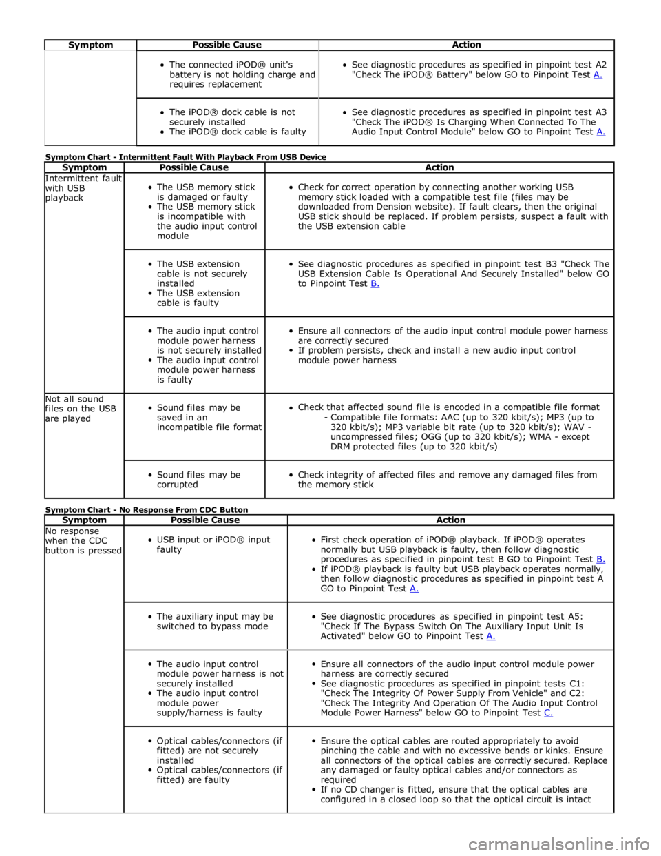
Symptom Possible Cause Action
The connected iPOD® unit's
battery is not holding charge and
requires replacement
See diagnostic procedures as specified in pinpoint test A2
"Check The iPOD® Battery" below GO to Pinpoint Test A.
The iPOD® dock cable is not
securely installed
The iPOD® dock cable is faulty
See diagnostic procedures as specified in pinpoint test A3
"Check The iPOD® Is Charging When Connected To The
Audio Input Control Module" below GO to Pinpoint Test A. Symptom Chart - Intermittent Fault With Playback From USB Device
Symptom Possible Cause Action Intermittent fault
with USB
playback
The USB memory stick
is damaged or faulty
The USB memory stick
is incompatible with
the audio input control
module
Check for correct operation by connecting another working USB
memory stick loaded with a compatible test file (files may be
downloaded from Dension website). If fault clears, then the original
USB stick should be replaced. If problem persists, suspect a fault with
the USB extension cable
The USB extension
cable is not securely
installed
The USB extension
cable is faulty
See diagnostic procedures as specified in pinpoint test B3 "Check The
USB Extension Cable Is Operational And Securely Installed" below GO
to Pinpoint Test B.
The audio input control
module power harness
is not securely installed
The audio input control
module power harness
is faulty
Ensure all connectors of the audio input control module power harness
are correctly secured
If problem persists, check and install a new audio input control
module power harness Not all sound
files on the USB
are played
Sound files may be
saved in an
incompatible file format
Check that affected sound file is encoded in a compatible file format
- Compatible file formats: AAC (up to 320 kbit/s); MP3 (up to
320 kbit/s); MP3 variable bit rate (up to 320 kbit/s); WAV -
uncompressed files; OGG (up to 320 kbit/s); WMA - except
DRM protected files (up to 320 kbit/s)
Sound files may be
corrupted
Check integrity of affected files and remove any damaged files from
the memory stick Symptom Chart - No Response From CDC Button
Symptom Possible Cause Action No response
when the CDC
button is pressed
USB input or iPOD® input
faulty
First check operation of iPOD® playback. If iPOD® operates
normally but USB playback is faulty, then follow diagnostic
procedures as specified in pinpoint test B GO to Pinpoint Test B. If iPOD® playback is faulty but USB playback operates normally,
then follow diagnostic procedures as specified in pinpoint test A
GO to Pinpoint Test A.
The auxiliary input may be
switched to bypass mode
See diagnostic procedures as specified in pinpoint test A5:
"Check If The Bypass Switch On The Auxiliary Input Unit Is
Activated" below GO to Pinpoint Test A.
The audio input control
module power harness is not
securely installed
The audio input control
module power
supply/harness is faulty
Ensure all connectors of the audio input control module power
harness are correctly secured
See diagnostic procedures as specified in pinpoint tests C1:
"Check The Integrity Of Power Supply From Vehicle" and C2:
"Check The Integrity And Operation Of The Audio Input Control
Module Power Harness" below GO to Pinpoint Test C.
Optical cables/connectors (if
fitted) are not securely
installed
Optical cables/connectors (if
fitted) are faulty
Ensure the optical cables are routed appropriately to avoid
pinching the cable and with no excessive bends or kinks. Ensure
all connectors of the optical cables are correctly secured. Replace
any damaged or faulty optical cables and/or connectors as
required
If no CD changer is fitted, ensure that the optical cables are
configured in a closed loop so that the optical circuit is intact
Page 2012 of 3039
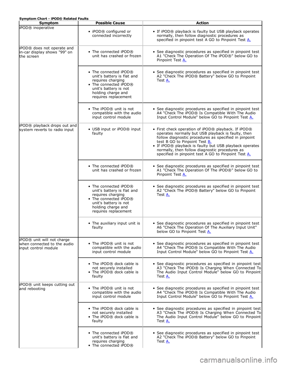
Symptom Chart - iPOD® Related Faults
Symptom Possible Cause Action iPOD® inoperative
iPOD® configured or
connected incorrectly
If iPOD® playback is faulty but USB playback operates
normally, then follow diagnostic procedures as
specified in pinpoint test A GO to Pinpoint Test A. iPOD® does not operate and
in-car display shows "99" on
the screen
The connected iPOD®
unit has crashed or frozen
See diagnostic procedures as specified in pinpoint test
A1 "Check The Operation Of The iPOD®" below GO to
Pinpoint Test A.
The connected iPOD®
unit's battery is flat and
requires charging
The connected iPOD®
unit's battery is not
holding charge and
requires replacement
See diagnostic procedures as specified in pinpoint test
A2 "Check The iPOD® Battery" below GO to Pinpoint
Test A.
The iPOD® unit is not
compatible with the audio
input control module
See diagnostic procedures as specified in pinpoint test
A4 "Check The iPOD® Is Compatible With The Audio
Input Control Module" below GO to Pinpoint Test A. iPOD® playback drops out and
system reverts to radio input
USB input or iPOD® input
faulty
First check operation of iPOD® playback. If iPOD®
operates normally but USB playback is faulty, then
follow diagnostic procedures as specified in pinpoint
test B GO to Pinpoint Test B. If iPOD® playback is faulty but USB playback operates
normally, then follow diagnostic procedures as
specified in pinpoint test A GO to Pinpoint Test A.
The connected iPOD®
unit has crashed or frozen
See diagnostic procedures as specified in pinpoint test
A1 "Check The Operation Of The iPOD®" below GO to
Pinpoint Test A.
The connected iPOD®
unit's battery is flat and
requires charging
The connected iPOD®
unit's battery is not
holding charge and
requires replacement
See diagnostic procedures as specified in pinpoint test
A2 "Check The iPOD® Battery" below GO to Pinpoint
Test A.
The auxiliary input unit is
faulty
See diagnostic procedures as specified in pinpoint test
A6 "Check The Operation Of The Auxiliary Input Unit"
below GO to Pinpoint Test A. iPOD® unit will not charge
when connected to the audio
input control module
The iPOD® unit is not
compatible with the audio
input control module
See diagnostic procedures as specified in pinpoint test
A4 "Check The iPOD® Is Compatible With The Audio
Input Control Module" below GO to Pinpoint Test A.
The iPOD® dock cable is
not securely installed
The iPOD® dock cable is
faulty
See diagnostic procedures as specified in pinpoint test
A3 "Check The iPOD® Is Charging When Connected To
The Audio Input Control Module" below GO to Pinpoint
Test A. iPOD® unit keeps cutting out
and rebooting
The iPOD® unit is not
compatible with the audio
input control module
See diagnostic procedures as specified in pinpoint test
A4 "Check The iPOD® Is Compatible With The Audio
Input Control Module" below GO to Pinpoint Test A.
The iPOD® dock cable is
not securely installed
The iPOD® dock cable is
faulty
See diagnostic procedures as specified in pinpoint test
A3 "Check The iPOD® Is Charging When Connected To
The Audio Input Control Module" below GO to Pinpoint
Test A.
The connected iPOD®
unit's battery is flat and
requires charging
The connected iPOD®
See diagnostic procedures as specified in pinpoint test
A2 "Check The iPOD® Battery" below GO to Pinpoint
Test A.