2010 JAGUAR XFR airbag
[x] Cancel search: airbagPage 1829 of 3039
module and fuel injector operating data from the ECM.
A 'Trip' button is located on the end of the LH (left-hand) multifunction switch and allows the driver to access, in sequence, the
available trip information by repeatedly pressing the button. The trip information is displayed in the following order:
Trip distance – The trip distance since the last reset is displayed
Average speed – The average speed since the last reset is displayed
Average fuel consumption – The average fuel consumption since the last reset is displayed
Range – The range is displayed showing the distance which can be travelled until the fuel gage reads empty. If the
range display shows dashes (-), this indicates a failure with one or both of the fuel level sensors.
The trip computer has three independent memories; A, B and Auto. Memories A and B can be set independently. The Auto
memory is reset after each ignition cycle and therefore only contains information relating the current journey.
The trip information can also be accessed from the TSD located in the center console. The TSD allows the same information
available with the trip button on the multifunction switch to be displayed on the TSD, with the addition of the option to reset
the values in the A and B memories.
If the battery is disconnected, all trip data in memories A, B and Auto are erased.
Fuel Level Display
The fuel level display is a linear LCD display to show the usable fuel tank contents. The level display is active at all times when the ignition is on. Low fuel level is displayed as a LOW FUEL LEVEL message and an amber warning triangle in the
message center.
The fuel level is obtained by fuel level sensors in the fuel tank. These are monitored by the RJB software and their output resistance values, corresponding fuel quantity, are transmitted to the instrument cluster on the medium speed CAN bus. The instrument cluster uses the two level sensor signals to calculate the fuel tank contents. This calculation takes into account
fuel movement in the tank to display a steady fuel quantity in the LCD.
The fuel level information is transmitted on the medium speed and high speed CAN bus for use by other vehicle system modules.
AUDIBLE WARNINGS
The instrument cluster can generate audible warnings to alert the driver to a displayed message and change of vehicle
operating condition. The audible warning is generated by a sounder located within the instrument cluster. The audible warnings
can be generated for the warnings below and are listed in order of priority, with the first being the highest priority:
Seatbelt reminder
EPB (High Pitch)
ACC Driver Intervene 1
Airbag fault
Key in ignition switch
ASL overspeed
ACC Driver Intervene 2
EPB (Low Pitch)
Vehicle armed (entry delay)
JaguarDrive selector not in park
Valet mode
Lights on reminder
Hood operation
Passive Entry / Passive Start (PEPS)
Memory set
Turn signal indicators
Seat Belt Minder.
The audible warnings can take the form of a single chime, a number of chimes or a continuous chime. The audible warnings are
initiated by a CAN message request from the requesting sub-system control module or by the instrument cluster software.
Page 2095 of 3039

DTC Description Possible Causes Action Write target SID
synchronisation error
following re-programming
Noise/EMC related error B100A63
Fuel Pump
Authorisation
RJB fault
Low speed CAN fault
Instrument cluster fault
Low battery voltage <9V Check power and ground supplies to RJB and instrument cluster.
Check CAN communications between RJB and instrument cluster.
Check battery is in fully charged and serviceable condition, refer
to the battery care manual B102612
Steering Column
Lock
Steering column lock
ground circuit - short to
power Refer to the electrical circuit diagrams and check steering column
lock ground circuit for short to power B108783 LIN Bus "A"
The checksum of the
received LIN frame is
incorrect Check the battery monitoring system and rear parking aid system
for DTCs and refer to relevant DTC Index B108786 LIN Bus "A"
The header of the LIN
message received is
incorrect Carry out any pinpoint test associated with this DTC using the
manufacturer approved diagnostic system. Check the battery
monitoring system and rear parking aid system for DTCs and
refer to relevant DTC Index B108788 LIN Bus "A"
Battery monitoring
system LIN circuit - short
to ground, power Carry out any pinpoint test associated with this DTC using the
manufacturer approved diagnostic system. Refer to the electrical
circuit diagrams and check battery monitoring system LIN circuit
for short to ground, power B108A23 Start Button
Start/Stop switch digital
input signal circuit -
stuck low Carry out any pinpoint test associated with this DTC using the
manufacturer approved diagnostic system. Refer to the electrical
circuit diagrams and check Start/Stop switch digital input signal
circuit for short to ground B10A111 Trailer Tow
Detection
Trailer tow detection
digital input circuit -
short to ground Carry out any pinpoint test associated with this DTC using the
manufacturer approved diagnostic system. Refer to the electrical
circuit diagrams and check trailer tow detection digital input
circuit for short to ground B10AF12 Blower Fan Relay
High Side output not
driven - Diagnosis
feedback indicates output
is short to power Refer to the electrical circuit diagrams and check blower motor
supply circuit for short to power B10AF14 Blower Fan Relay
High Side output not
driven - Diagnosis
feedback indicates output
is short to ground, open
circuit Refer to the electrical circuit diagrams and check blower motor
supply circuit for short to ground, open circuit B10AF93 Blower Fan Relay
High Side output not
driven - Diagnosis
feedback indicates output
is at open load or short
to power Carry out any pinpoint test associated with this DTC using the
manufacturer approved diagnostic system. Refer to the electrical
circuit diagrams and check blower motor supply circuit for short
to power, open circuit B10DD11 Airbag Deployed
Airbag deployed digital
input signal circuit - short
to ground Carry out any pinpoint test associated with this DTC using the
manufacturer approved diagnostic system. Refer to the electrical
circuit diagrams and check airbag deployed digital input signal
circuit for short to ground B10DD15 Airbag Deployed
Airbag deployed digital
input signal circuit - short
to power, open circuit Carry out any pinpoint test associated with this DTC using the
manufacturer approved diagnostic system. Refer to the electrical
circuit diagrams and check airbag deployed digital input signal
circuit for short to power, open circuit B10DD38 Airbag Deployed
Signal frequency incorrect Check the RCM for related DTCs and refer to the relevant DTC
Index B10DE11
Low Fuel Warning
Switch
Diesel run-dry switch
analogue input circuit -
short to ground Carry out any pinpoint test associated with this DTC using the
manufacturer approved diagnostic system. Refer to the electrical
circuit diagrams and check diesel run-dry switch analogue input
circuit for short to ground www.JagDocs.com
Page 2311 of 3039
Seating - Seats - Overview
Description and Operation
OVERVIEW
Leather Seat Covers Published: 20-Nov-2013
Leather is a natural product, therefore it bears natural characteristics, such as grain variations, growth & bush marks. These
non-weakening marks show the true nature of the hide and are the hallmarks of Leather. In order to maintain the beauty of the
vehicles natural Leather upholstery it requires regular cleaning, which if neglected, may cause deterioration. Where dust and
dirt are allowed to accumulate and become ingrained in the surface of the Leather, the upholstery may become permanently
damaged.
Light coloured upholstery can be particularly susceptible to soiling and staining and care should be taken to ensure that where
there is evidence of any soiling or staining on the upholstery then this should be cleaned immediately using the Jaguar/Land
Rover approved products, failure to do this could lead to the stain becoming permanent, this applies to all leather upholstery
and is not colour specific.
Leather trimmed seats will naturally exhibit areas of creasing and wrinkling over a period of time and is a normal characteristic
as the Leather ages.
Particular care should be taken where there is evidence of soiling or staining on the leather, this should be cleaned
immediately. Failure to do this could lead to the stain becoming permanent.
Particular care should be taken to prevent damage from studs, zips and buckles.
NOTES:
Please refer to Leather care label attached to seats for more information.
Creasing and wrinkling does not represent a manufacturing defect.
Damage from studs, zips and buckles do not represent manufacturing defects.
Use only Jaguar/Land Rover approved products in accordance with the instructions for use.
General
A number of front seating options are available. An 8-way electrically adjustable driver's seat is complemented by an 8-way
electrically adjustable passenger seat. A 10-way electrically adjustable driver's seat is complemented by an 10-way electrically
adjustable front passenger seat. A 16-way electrically adjustable driver's seat is complemented by a 12-way electrically
adjustable front passenger seat.
On non-memory seats, the operation of the seats is controlled directly from the driver's seat switchpack. On memory seats,
the operation of the seat motors is controlled by a seat control module which is located on the underside of the driver's seat
frame.
The driver's seat is fitted with a seat position sensor which is located on the seat rail. The sensor is used by the RCM
(restraints control module) to determine the seat position and adjust the inflation time of the airbag deployment accordingly.
Refer to: Air Bag and Safety Belt Pretensioner Supplemental Restraint System (SRS) (501-20B Supplemental Restraint System, Description and Operation).
Page 2609 of 3039
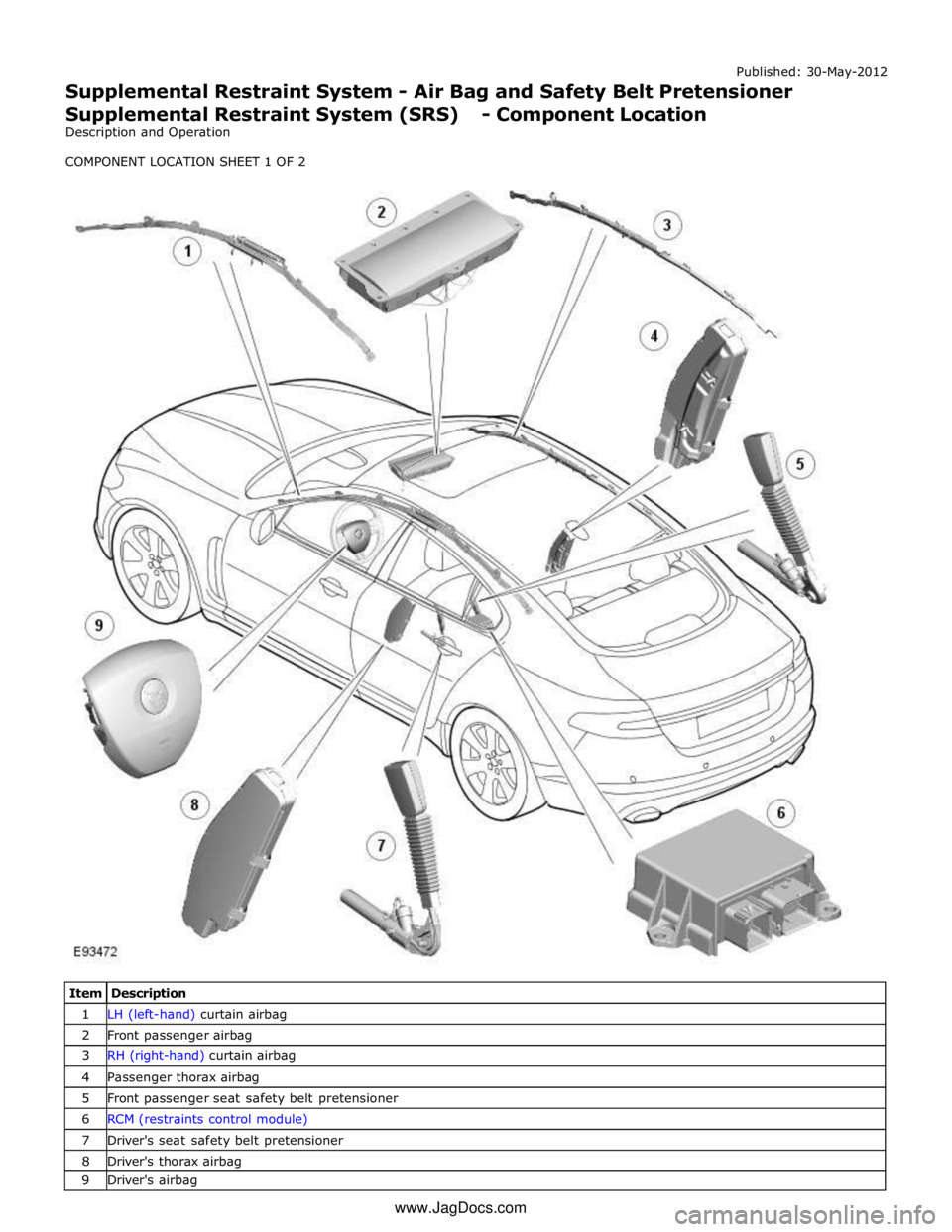
1 LH (left-hand) curtain airbag 2 Front passenger airbag 3 RH (right-hand) curtain airbag 4 Passenger thorax airbag 5 Front passenger seat safety belt pretensioner 6 RCM (restraints control module) 7 Driver's seat safety belt pretensioner 8 Driver's thorax airbag 9 Driver's airbag www.JagDocs.com
Page 2610 of 3039
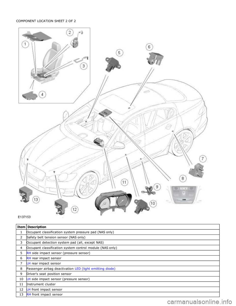
1 Occupant classification system pressure pad (NAS only) 2 Safety belt tension sensor (NAS only) 3 Occupant detection system pad (all, except NAS) 4 Occupant classification system control module (NAS only) 5 RH side impact sensor (pressure sensor) 6 RH rear impact sensor 7 LH rear impact sensor 8 Passenger airbag deactivation LED (light emitting diode) 9 Driver's seat position sensor 10 LH side impact sensor (pressure sensor) 11 Instrument cluster 12 LH front impact sensor 13 RH front impact sensor
Page 2611 of 3039
Published: 30-May-2012
Supplemental Restraint System - Air Bag and Safety Belt Pretensioner
Supplemental Restraint System (SRS) - Overview
Description and Operation
OVERVIEW
WARNING: All pyrotechnic devices are dangerous. Before performing any procedures on any pyrotechnic device, read all
information contained within the Standard Workshop Practices section of this manual.
Refer to: Standard Workshop Practices (100-00 General Information, Description and Operation).
The SRS (supplemental restraint system) provides additional protection for the vehicle occupants in certain impact conditions.
The system is controlled by the RCM (restraints control module), which is mounted beneath the floor console. The system
includes twin stage drivers and front passenger airbags.
The RCM receives inputs from various sensors around the vehicle and determines which, if any, airbags should be deployed.
The SRS features an occupant detection system. The occupant detection system comprises a mat fitted inside the front passenger seat. By monitoring the condition of the mat, the RCM can determine if the front passenger seat is occupied. It uses this information to determine which airbags to deploy in the event of an impact. This information is also used to illuminate the
safety belt instrument cluster warning lamp if the front passenger seat is occupied and the safety belt is not engaged.
North American Specification (NAS) vehicles also feature an occupant classification system. The occupant classification system
comprises a control module, pressure pad and safety belt tension sensor. The system can determine the size and weight of the
front seat passenger. This information is transmitted to the RCM over the high speed CAN (controller area network) bus. The RCM uses this information to help determine which airbags to deploy in the event of an impact.
Page 2613 of 3039
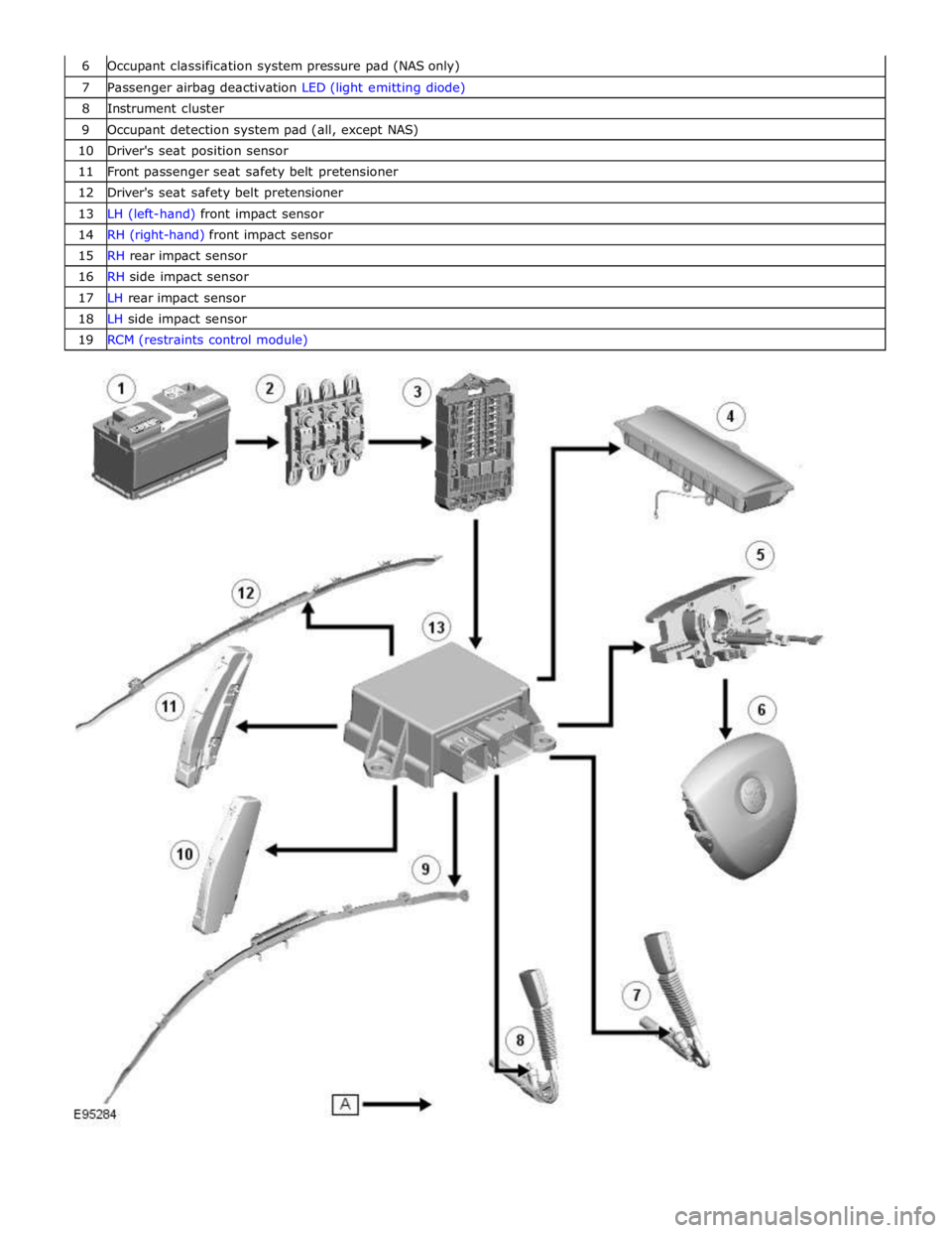
6 Occupant classification system pressure pad (NAS only) 7 Passenger airbag deactivation LED (light emitting diode) 8 Instrument cluster 9 Occupant detection system pad (all, except NAS) 10 Driver's seat position sensor 11 Front passenger seat safety belt pretensioner 12 Driver's seat safety belt pretensioner 13 LH (left-hand) front impact sensor 14 RH (right-hand) front impact sensor 15 RH rear impact sensor 16 RH side impact sensor 17 LH rear impact sensor 18 LH side impact sensor 19 RCM (restraints control module)
Page 2614 of 3039
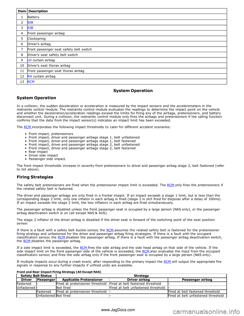
Item Description 1 Battery 2 BJB 3 RJB 4 Front passenger airbag 5 Clockspring 6 Driver's airbag 7 Front passenger seat safety belt switch 8 Driver's seat safety belt switch 9 LH curtain airbag 10 Driver's seat thorax airbag 11 Front passenger seat thorax airbag 12 RH curtain airbag 13 RCM
System Operation System Operation
In a collision, the sudden deceleration or acceleration is measured by the impact sensors and the accelerometers in the
restraints control module. The restraints control module evaluates the readings to determine the impact point on the vehicle
and whether the deceleration/acceleration readings exceed the limits for firing any of the airbags, pretensioners, and battery
disconnect unit. During a collision, the restraints control module only fires the airbags and pretensioners if the safing function
confirms that the data from the impact sensor(s) indicates an impact limit has been exceeded.
The RCM incorporates the following impact thresholds to cater for different accident scenarios: Front impact, pretensioners
Front impact, driver and passenger airbags stage 1, belt unfastened
Front impact, driver and passenger airbags stage 1, belt fastened
Front impact, driver and passenger airbags stage 2, belt unfastened
Front impact, driver and passenger airbags stage 2, belt fastened
Rear impact
Driver side impact
Passenger side impact.
The front impact thresholds increase in severity from pretensioners to driver and passenger airbag stage 2, belt fastened (refer
to list above).
Firing Strategies
The safety belt pretensioners are fired when the pretensioner impact limit is exceeded. The RCM only fires the pretensioners if the related safety belt is fastened.
The driver and passenger airbags are only fired in a frontal impact. If an impact exceeds a stage 1 limit, but is less than the
corresponding stage 2 limit, only one inflator in each airbag is fired (stage 2 is still fired for disposal after a delay of 100ms).
If an impact exceeds the stage 2 limit, the two inflators in each airbag are fired simultaneously.
The passenger airbag is disabled unless the front passenger seat is occupied by a large person (NAS only), or the passenger
airbag deactivation switch is on (all except NAS & AUS).
The stage 2 inflator of the driver airbag is disabled if the driver seat is forward of the switching point of the seat position
sensor.
If there is a fault with a safety belt buckle sensor, the RCM assumes the related safety belt is fastened for the pretensioner firing strategy and unfastened for the driver and passenger airbag firing strategies. If there is a fault with the occupant
classification sensor, the RCM disables the passenger airbag. If there is a fault with the passenger airbag deactivation switch, the RCM disables the passenger airbag.
If a side impact limit is exceeded, the RCM fires the side airbag and the side head airbag on that side of the vehicle. If the side impact limit on the front passenger side of the vehicle is exceeded, the RCM also evaluates the input from the occupant classification sensor, and fires the side airbag only if the front passenger seat is occupied by a large person (NAS only).
If multiple impacts occur during a crash event, after responding to the primary impact the RCM will output the appropriate fire signals in response to any further impacts if unfired units are available.
Front and Rear Impact Firing Strategy (All Except NAS)
Safety Belt Status Strategy Driver Passenger Applicable Pretensioner Driver airbag Passenger airbag Fastened - Fired at pretensioner threshold Fired at belt fastened threshold - Unfastened - Not fired Fired at belt unfastened threshold - - Fastened Fired at pretensioner threshold - Fired at belt fastened threshold - Unfastened Not fired - Fired at belt unfastened threshold www.JagDocs.com