2010 JAGUAR XFR airbag
[x] Cancel search: airbagPage 782 of 3039
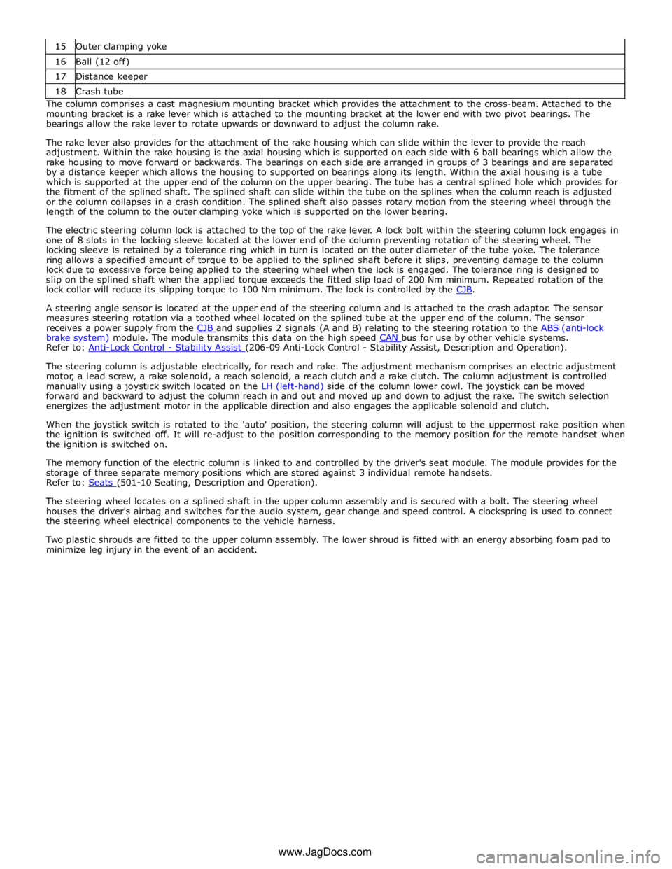
16 Ball (12 off) 17 Distance keeper 18 Crash tube The column comprises a cast magnesium mounting bracket which provides the attachment to the cross-beam. Attached to the
mounting bracket is a rake lever which is attached to the mounting bracket at the lower end with two pivot bearings. The
bearings allow the rake lever to rotate upwards or downward to adjust the column rake.
The rake lever also provides for the attachment of the rake housing which can slide within the lever to provide the reach
adjustment. Within the rake housing is the axial housing which is supported on each side with 6 ball bearings which allow the
rake housing to move forward or backwards. The bearings on each side are arranged in groups of 3 bearings and are separated
by a distance keeper which allows the housing to supported on bearings along its length. Within the axial housing is a tube
which is supported at the upper end of the column on the upper bearing. The tube has a central splined hole which provides for
the fitment of the splined shaft. The splined shaft can slide within the tube on the splines when the column reach is adjusted
or the column collapses in a crash condition. The splined shaft also passes rotary motion from the steering wheel through the
length of the column to the outer clamping yoke which is supported on the lower bearing.
The electric steering column lock is attached to the top of the rake lever. A lock bolt within the steering column lock engages in
one of 8 slots in the locking sleeve located at the lower end of the column preventing rotation of the steering wheel. The
locking sleeve is retained by a tolerance ring which in turn is located on the outer diameter of the tube yoke. The tolerance
ring allows a specified amount of torque to be applied to the splined shaft before it slips, preventing damage to the column
lock due to excessive force being applied to the steering wheel when the lock is engaged. The tolerance ring is designed to
slip on the splined shaft when the applied torque exceeds the fitted slip load of 200 Nm minimum. Repeated rotation of the
lock collar will reduce its slipping torque to 100 Nm minimum. The lock is controlled by the CJB.
A steering angle sensor is located at the upper end of the steering column and is attached to the crash adaptor. The sensor
measures steering rotation via a toothed wheel located on the splined tube at the upper end of the column. The sensor
receives a power supply from the CJB and supplies 2 signals (A and B) relating to the steering rotation to the ABS (anti-lock brake system) module. The module transmits this data on the high speed CAN bus for use by other vehicle systems. Refer to: Anti-Lock Control - Stability Assist (206-09 Anti-Lock Control - Stability Assist, Description and Operation).
The steering column is adjustable electrically, for reach and rake. The adjustment mechanism comprises an electric adjustment
motor, a lead screw, a rake solenoid, a reach solenoid, a reach clutch and a rake clutch. The column adjustment is controlled
manually using a joystick switch located on the LH (left-hand) side of the column lower cowl. The joystick can be moved
forward and backward to adjust the column reach in and out and moved up and down to adjust the rake. The switch selection
energizes the adjustment motor in the applicable direction and also engages the applicable solenoid and clutch.
When the joystick switch is rotated to the 'auto' position, the steering column will adjust to the uppermost rake position when
the ignition is switched off. It will re-adjust to the position corresponding to the memory position for the remote handset when
the ignition is switched on.
The memory function of the electric column is linked to and controlled by the driver's seat module. The module provides for the
storage of three separate memory positions which are stored against 3 individual remote handsets.
Refer to: Seats (501-10 Seating, Description and Operation).
The steering wheel locates on a splined shaft in the upper column assembly and is secured with a bolt. The steering wheel
houses the driver's airbag and switches for the audio system, gear change and speed control. A clockspring is used to connect
the steering wheel electrical components to the vehicle harness.
Two plastic shrouds are fitted to the upper column assembly. The lower shroud is fitted with an energy absorbing foam pad to
minimize leg injury in the event of an accident.
www.JagDocs.com
Page 797 of 3039
Published: 11-May-2011
Steering Column Switches - Steering Column Switches - Overview
Description and Operation
OVERVIEW
The steering column multifunction switch is situated on the steering column and consists of the wiper switch, the turn signal
indicator/lighting switch and the trip computer switch.
The RH (right-hand) multifunction switch controls the following windshield wiper functions:
Flick wipe
Intermittent wipe
Slow speed wipe
High speed wipe
Wash/Wipe
Headlamp powerwash
Rain sensing / variable wipe selection.
The LH (left-hand) multifunction switch controls the following functions:
Turn signal indicators
Side lamps
Headlamps
Auto lamps
High/low beam
Headlamp flash
Headlamp timer
Trip computer.
The steering column adjustment switch is located in the steering column lower shroud on the LH side. The switch is a 4 position 'joystick' which controls reach and rake adjustment.
The trip button allows the driver to cycle though an option menu and also reset trip cycle mileage calculations. The trip
computer information is displayed in the instrument cluster message centre.
Steering wheel mounted switches on the LH side of the driver's airbag, control the audio and telephone functions. Switches on the RH side of the driver's airbag, control the speed control functions. The steering wheel has an internal heating element. This is controlled by the driver via the Touch Screen Display (TSD). www.JagDocs.com
Page 801 of 3039

battery power supply to be passed via the slip ring assembly in the steering wheel to the heated steering wheel control
module. The steering wheel module supplies power to the steering wheel heater element and also monitors the temperature
via a NTC (negative temperature coefficient) temperature sensor incorporated into the heater element. The control module
varies the power supply to the element to maintain the steering wheel rim at the optimum temperature.
Component Description STEERING COLUMN MULTIFUNCTION SWITCHES
The steering column multifunction switches are situated on the steering column and consists of the wiper switch, the turn
signal indicator/lighting switch and the trip computer switch.
The steering column adjustment switch is located in the steering column lower shroud on the LH side. The switch is a 4 position 'joystick' which controls reach and rake adjustment.
Steering wheel mounted switches on the LH side of the driver's airbag, control the audio and telephone functions. Switches on the RH side of the driver's airbag, control the speed control functions. For additional information, refer to:
Audio System (415-01A Information and Entertainment System, Description and Operation), Speed Control (310-03A, Description and Operation),
Speed Control (310-03B, Description and Operation),
Speed Control (310-03C, Description and Operation).
Two transmission paddle switches are located at the rear of the steering wheel.
Refer to: External Controls (307-05, Description and Operation).
LH Multifunction Switch
Item Description 1 High beam 2 Lighting control rotary switch 3 RH turn signal indicator 4 Headlamp flash 5 LH turn signal indicator 6 Trip computer function button The LH multifunction switch controls the following windshield wiper functions:
Page 1784 of 3039
7 Instrument cluster 8 Steering column motor 9 High speed CAN bus connection to other vehicle systems 10 Engine oil pressure switch 11 Steering column adjustment switch 12 Brake fluid level switch 13 LH (left-hand) steering column multifunction switch 14 Start control module 15 Clockspring 16 RH (right-hand) steering column multifunction switch 17 Engine coolant level sensor 18 Auxiliary lighting switch
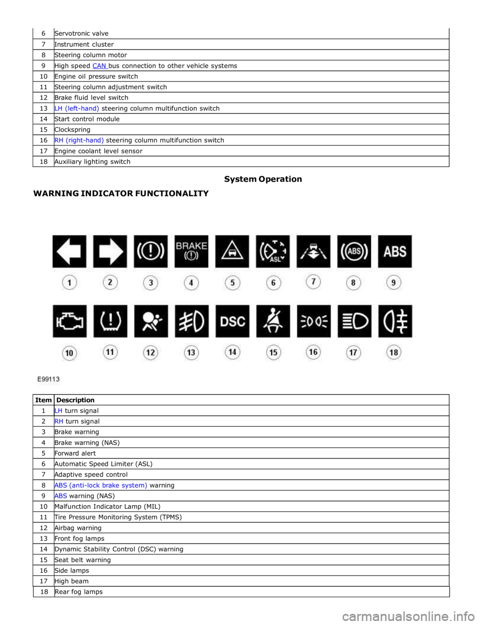
WARNING INDICATOR FUNCTIONALITY System Operation
Item Description 1 LH turn signal 2 RH turn signal 3 Brake warning 4 Brake warning (NAS) 5 Forward alert 6 Automatic Speed Limiter (ASL) 7 Adaptive speed control 8 ABS (anti-lock brake system) warning 9 ABS warning (NAS) 10 Malfunction Indicator Lamp (MIL) 11 Tire Pressure Monitoring System (TPMS) 12 Airbag warning 13 Front fog lamps 14 Dynamic Stability Control (DSC) warning 15 Seat belt warning 16 Side lamps 17 High beam 18 Rearfoglamps
Page 1786 of 3039
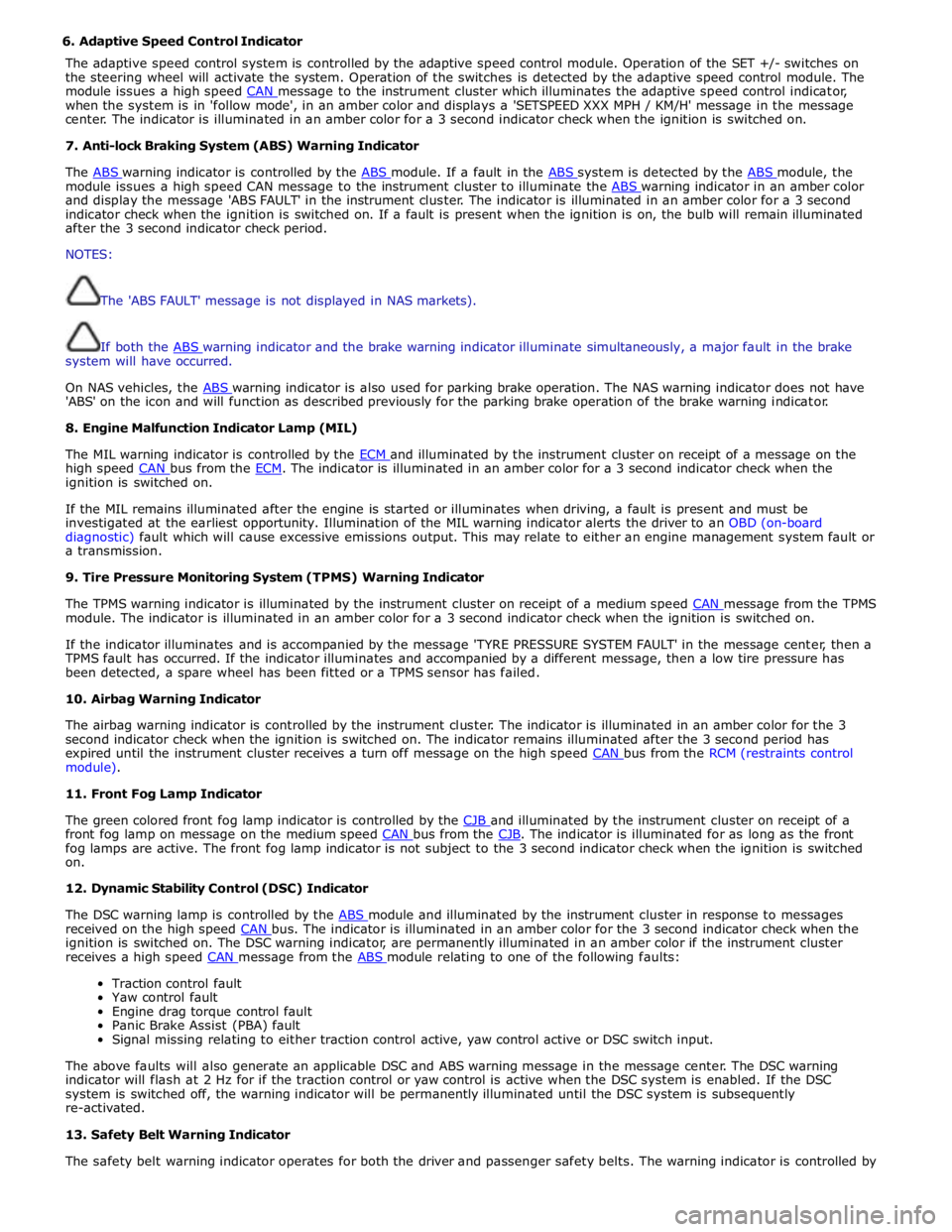
6. Adaptive Speed Control Indicator
The adaptive speed control system is controlled by the adaptive speed control module. Operation of the SET +/- switches on
the steering wheel will activate the system. Operation of the switches is detected by the adaptive speed control module. The
module issues a high speed CAN message to the instrument cluster which illuminates the adaptive speed control indicator, when the system is in 'follow mode', in an amber color and displays a 'SETSPEED XXX MPH / KM/H' message in the message
center. The indicator is illuminated in an amber color for a 3 second indicator check when the ignition is switched on.
7. Anti-lock Braking System (ABS) Warning Indicator
The ABS warning indicator is controlled by the ABS module. If a fault in the ABS system is detected by the ABS module, the module issues a high speed CAN message to the instrument cluster to illuminate the ABS warning indicator in an amber color and display the message 'ABS FAULT' in the instrument cluster. The indicator is illuminated in an amber color for a 3 second
indicator check when the ignition is switched on. If a fault is present when the ignition is on, the bulb will remain illuminated
after the 3 second indicator check period.
NOTES:
The 'ABS FAULT' message is not displayed in NAS markets).
If both the ABS warning indicator and the brake warning indicator illuminate simultaneously, a major fault in the brake system will have occurred.
On NAS vehicles, the ABS warning indicator is also used for parking brake operation. The NAS warning indicator does not have 'ABS' on the icon and will function as described previously for the parking brake operation of the brake warning indicator.
8. Engine Malfunction Indicator Lamp (MIL)
The MIL warning indicator is controlled by the ECM and illuminated by the instrument cluster on receipt of a message on the high speed CAN bus from the ECM. The indicator is illuminated in an amber color for a 3 second indicator check when the ignition is switched on.
If the MIL remains illuminated after the engine is started or illuminates when driving, a fault is present and must be
investigated at the earliest opportunity. Illumination of the MIL warning indicator alerts the driver to an OBD (on-board
diagnostic) fault which will cause excessive emissions output. This may relate to either an engine management system fault or
a transmission.
9. Tire Pressure Monitoring System (TPMS) Warning Indicator
The TPMS warning indicator is illuminated by the instrument cluster on receipt of a medium speed CAN message from the TPMS module. The indicator is illuminated in an amber color for a 3 second indicator check when the ignition is switched on.
If the indicator illuminates and is accompanied by the message 'TYRE PRESSURE SYSTEM FAULT' in the message center, then a
TPMS fault has occurred. If the indicator illuminates and accompanied by a different message, then a low tire pressure has
been detected, a spare wheel has been fitted or a TPMS sensor has failed.
10. Airbag Warning Indicator
The airbag warning indicator is controlled by the instrument cluster. The indicator is illuminated in an amber color for the 3
second indicator check when the ignition is switched on. The indicator remains illuminated after the 3 second period has
expired until the instrument cluster receives a turn off message on the high speed CAN bus from the RCM (restraints control module).
11. Front Fog Lamp Indicator
The green colored front fog lamp indicator is controlled by the CJB and illuminated by the instrument cluster on receipt of a front fog lamp on message on the medium speed CAN bus from the CJB. The indicator is illuminated for as long as the front fog lamps are active. The front fog lamp indicator is not subject to the 3 second indicator check when the ignition is switched
on.
12. Dynamic Stability Control (DSC) Indicator
The DSC warning lamp is controlled by the ABS module and illuminated by the instrument cluster in response to messages received on the high speed CAN bus. The indicator is illuminated in an amber color for the 3 second indicator check when the ignition is switched on. The DSC warning indicator, are permanently illuminated in an amber color if the instrument cluster
receives a high speed CAN message from the ABS module relating to one of the following faults:
Traction control fault
Yaw control fault
Engine drag torque control fault
Panic Brake Assist (PBA) fault
Signal missing relating to either traction control active, yaw control active or DSC switch input.
The above faults will also generate an applicable DSC and ABS warning message in the message center. The DSC warning
indicator will flash at 2 Hz for if the traction control or yaw control is active when the DSC system is enabled. If the DSC
system is switched off, the warning indicator will be permanently illuminated until the DSC system is subsequently
re-activated.
13. Safety Belt Warning Indicator
The safety belt warning indicator operates for both the driver and passenger safety belts. The warning indicator is controlled by
Page 1788 of 3039
gage, odometer, trip distance and trip computer readouts. The trip distance and trip computer information is derived from
information supplied on the high speed CAN bus to the instrument cluster from the ABS module and the ECM.
The area above the message center displays the transmission gear position information and speed control related information.
The transmission information is supplied on the high speed CAN bus from the TCM (transmission control module).
NOTE: There is no engine coolant temperature gage displayed. If the engine coolant temperature increases to above a
predetermined threshold, a warning message is displayed in the message center. The message is sent from the ECM in a high speed CAN message to the instrument cluster.
TRANSMISSION GEAR SELECTION POSITION
The gear position display shows JaguarDrive selector position or selected gear when using the Jaguar Sequential Shift. The gear
selector module transmits a CAN message to the instrument cluster for gear selector lever position. The module also outputs a 'not in park' signal to the instrument cluster. The TCM transmits a high speed CAN message to the instrument cluster with data containing the selected gear when in Jaguar Sequential Shift mode.
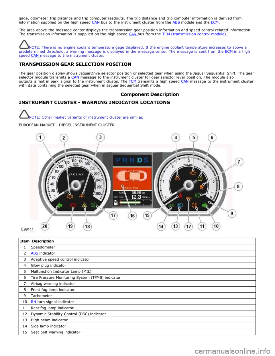
Component Description INSTRUMENT CLUSTER - WARNING INDICATOR LOCATIONS
NOTE: Other market variants of instrument cluster are similar.
EUROPEAN MARKET - DIESEL INSTRUMENT CLUSTER
Item Description 1 Speedometer 2 ABS indicator 3 Adaptive speed control indicator 4 Glow plug indicator 5 Malfunction Indicator Lamp (MIL) 6 Tire Pressure Monitoring System (TPMS) indicator 7 Airbag warning indicator 8 Front fog lamp indicator 9 Tachometer 10 RH turn signal indicator 11 Rear fog lamp indicator 12 Dynamic Stability Control (DSC) indicator 13 High beam indicator 14 Side lamp indicator 15 Seat belt warning indicator
Page 1789 of 3039
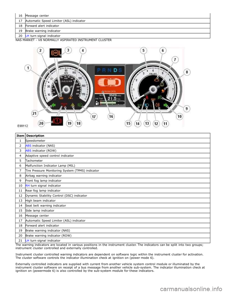
17 Automatic Speed Limiter (ASL) indicator 18 Forward alert indicator 19 Brake warning indicator 20 LH turn signal indicator NAS MARKET - V8 NORMALLY ASPIRATED INSTRUMENT CLUSTER
Item Description 1 Speedometer 2 ABS indicator (NAS) 3 ABS indicator (ROW) 4 Adaptive speed control indicator 5 Tachometer 6 Malfunction Indicator Lamp (MIL) 7 Tire Pressure Monitoring System (TPMS) indicator 8 Airbag warning indicator 9 Front fog lamp indicator 10 RH turn signal indicator 11 Rear fog lamp indicator 12 Dynamic Stability Control (DSC) indicator 13 High beam indicator 14 Seat belt warning indicator 15 Side lamp indicator 16 Message center 17 Automatic Speed Limiter (ASL) indicator 18 Forward alert indicator 19 Brake warning indicator (NAS) 20 Brake warning indicator (ROW) 21 LH turn signal indicator The warning indicators are located in various positions in the instrument cluster. The indicators can be split into two groups;
instrument cluster controlled and externally controlled.
Instrument cluster controlled warning indicators are dependent on software logic within the instrument cluster for activation.
The cluster software controls the indicator illumination check at ignition on (power mode 6).
Externally controlled indicators are supplied with current from another vehicle system control module or illuminated by the
instrument cluster software on receipt of a bus message from another vehicle sub-system. The indicator illumination check at
ignition on (powermode 6) is also controlled by the sub-system module for these indicators.
Page 1795 of 3039

ETM Test/no. Message Center Display Gauge/Indicator/Display
Tested.
Range
Description C: XXXX
G:XXXX
D: XXXX
H:XXXX 11 - Analogue
Inputs. ANALOG INPUTS.
#: RAW -
RATIO
0:XXX - XXXX
1:XXX - XXXX
2:XXX - XXXX
3.XXX - XXXX Cluster inputs. TDB. Displays Hex coding of inputs 0 - 3.
0 - Main beam / FTP 1
- Master light switch
2 - Power column joystick
switch
3 - DI / Hazard 12 - Analogue
Inputs. ANALOG INPUTS.
#: RAW -
RATIO
4:XXX - XXXX
5:XXX - XXXX
6:XXX - XXXX
7.XXX - XXXX Cluster inputs. TDB. Displays Hex coding of inputs 4 - 7.
4 - Auto lamp sensor
5 - battery in
6 - Pedal position
7 - Display temperature 13 - Analogue
Inputs. ANALOG INPUTS.
#: RAW -
RATIO
8:XXX - XXXX
9:XXX - XXXX
10:XXX -
XXXX
11.XXX -
XXXX Cluster inputs. TDB. Displays Hex coding of inputs 8 - 11.
8 - Power column Rake
position
9 - Power column Reach
position
10 - Auxiliary switch
11 - Power column mode
switch 14 - Analogue
Inputs. ANALOG INPUTS.
#: RAW -
RATIO
12:XXX -
XXXX
13:XXX -
XXXX
14:XXX -
XXXX
15.XXX -
XXXX Cluster inputs. TDB.
Displays Hex coding of inputs 12 -
15.
12 - Not used
13 -Airbag LED monitor
14 - Battery voltage
15 - Low brake fluid 15- Analogue
Inputs. ANALOG INPUTS.
#: RAW -
RATIO
16:XXX -
XXXX
17:XXX -
XXXX
18:XXX -
XXXX
19.XXX -
XXXX Cluster inputs. TDB.
Displays Hex coding of inputs 16-
19.
16 - Fog light switch
17 - Flick wipe switch
18 - Int. wipe switch
19 - Exit delay switch 16 - Analogue
Inputs. ANALOG INPUTS.
#: RAW -
Ratio
20:XXX -
XXXX
21:XXX -
XXXX
22:XXX -
XXXX
23.XXX -
XXXX Cluster inputs. TDB.
Displays Hex coding of inputs 20 -
23.
20 - Wash wipe switch
21 - Trip cycle switch
22 - dimmer level
23 - Master wipe switch 17 - Analogue
Inputs. ANALOG INPUTS.
#: RAW- Ratio
24:XXX -
XXXX Cluster inputs. TDB.
Displays Hex coding of inputs 24 -
27.
24 - Brake pad wear