2010 JAGUAR XFR Cooling sensor
[x] Cancel search: Cooling sensorPage 1431 of 3039
transmission functions. The Mechatronic valve block comprises the following components:
TCM
Pressure regulator solenoids
Shift control solenoid
Damper
Hydraulic spool valves
Selector valve
Temperature sensor
Turbine speed sensor
Output shaft speed sensor.
Sensors
Speed Sensors
The turbine speed sensor and the output shaft speed sensor are Hall effect type sensors located in the Mechatronic valve block
and are not serviceable items. The TCM monitors the signals from each sensor to determine the input (turbine) speed and the output shaft speed.
The turbine speed is monitored by the TCM to calculate the slip of the torque converter clutch and internal clutch slip. This signal allows the TCM to accurately control the slip timing during shifts and adjust clutch application or release pressure for overlap shift control.
The output shaft speed is monitored by the TCM and compared to engine speed signals received on the CAN bus from the ECM. Using a comparison of the two signals the TCM calculates the transmission slip ratio for plausibility and maintains adaptive pressure control.
Temperature Sensor
The temperature sensor is also located in the Mechatronic valve block. The TCM uses the temperature sensor signals to determine the temperature of the transmission fluid. These signals are used by the TCM to control the transmission operation to promote faster warm-up in cold conditions or to assist with fluid cooling by controlling the transmission operation when high
fluid temperatures are experienced. If the sensor fails, the TCM will use a default value and a fault code will be stored in the TCM.
Damper
There is one damper located in the valve housing. The damper is used to regulate and dampen the regulated pressure supplied
via EPRS. The damper is load dependent through modulation of the damper against return spring pressure.
The damper comprises a piston, a housing bore and a spring. The piston is subject to the pressure applied by the spring. The
bore has a connecting port to the function to which it applies. Fluid pressure applied to the applicable component (i.e. a
clutch) is also subjected to the full area of the piston, which moves against the opposing force applied by the spring. The
movement of the piston creates an action similar to a shock absorber, momentarily delaying the build up of pressure in the
circuit. This results in a more gradual application of clutches improving shift quality.
Spool Valves
The valve block spool valves control various functions of the transmission. The spool valves are of conventional design and are
operated by fluid pressure.
Each spool valve is located in its spool bore and held in a default (unpressurized) position by a spring. The spool bore has a
number of ports which allow fluid to flow to other valves and clutches to enable transmission operation. Each spool has a
piston which is waisted to allow fluid to be diverted into the applicable ports when the valve is operated.
When fluid pressure moves a spool, one or more ports in the spool bore are covered or uncovered. Fluid is prevented from
flowing or is allowed to flow around the applicable waisted area of the spool and into another uncovered port. The fluid is
either passed through galleries to actuate another spool, operate a clutch or is returned to the fluid pan.
Page 1664 of 3039
Published: 11-Jul-2014
Climate Control System - General Information - Climate Control System
Diagnosis and Testing
Principles of Operation
For a detailed description of the Climate Control System, refer to the relevant Description and Operation sections in the
Workshop Manual. REFER to:
Air Distribution and Filtering (412-01 Climate Control, Description and Operation), Air Distribution and Filtering (412-01 Climate Control, Description and Operation), Air Distribution and Filtering (412-01 Climate Control, Description and Operation), Heating and Ventilation (412-01 Climate Control, Description and Operation), Heating and Ventilation (412-01 Climate Control, Description and Operation), Heating and Ventilation (412-01 Climate Control, Description and Operation), Air Conditioning (412-01 Climate Control, Description and Operation), Air Conditioning (412-01 Climate Control, Description and Operation), Air Conditioning (412-01 Climate Control, Description and Operation), Control Components (412-01 Climate Control, Description and Operation), Control Components (412-01 Climate Control, Description and Operation), Control Components (412-01 Climate Control, Description and Operation), Electric Booster Heater (412-02 Auxiliary Climate Control, Description and Operation), Electric Booster Heater (412-02 Auxiliary Climate Control, Description and Operation), Electric Booster Heater (412-02 Auxiliary Climate Control, Description and Operation).
Inspection and Verification
WARNING: Servicing must be carried out by personnel familiar with both vehicle system and the charging and testing
equipment. All operations must be carried out in a well ventilated area away from open flame and heat sources.
CAUTION: Diagnosis by substitution from a donor vehicle is NOT acceptable. Substitution of control modules does not
guarantee confirmation of a fault, and may also cause additional faults in the vehicle being tested and/or the donor vehicle.
NOTE: Check and rectify basic faults before beginning diagnostic routines involving pinpoint tests.
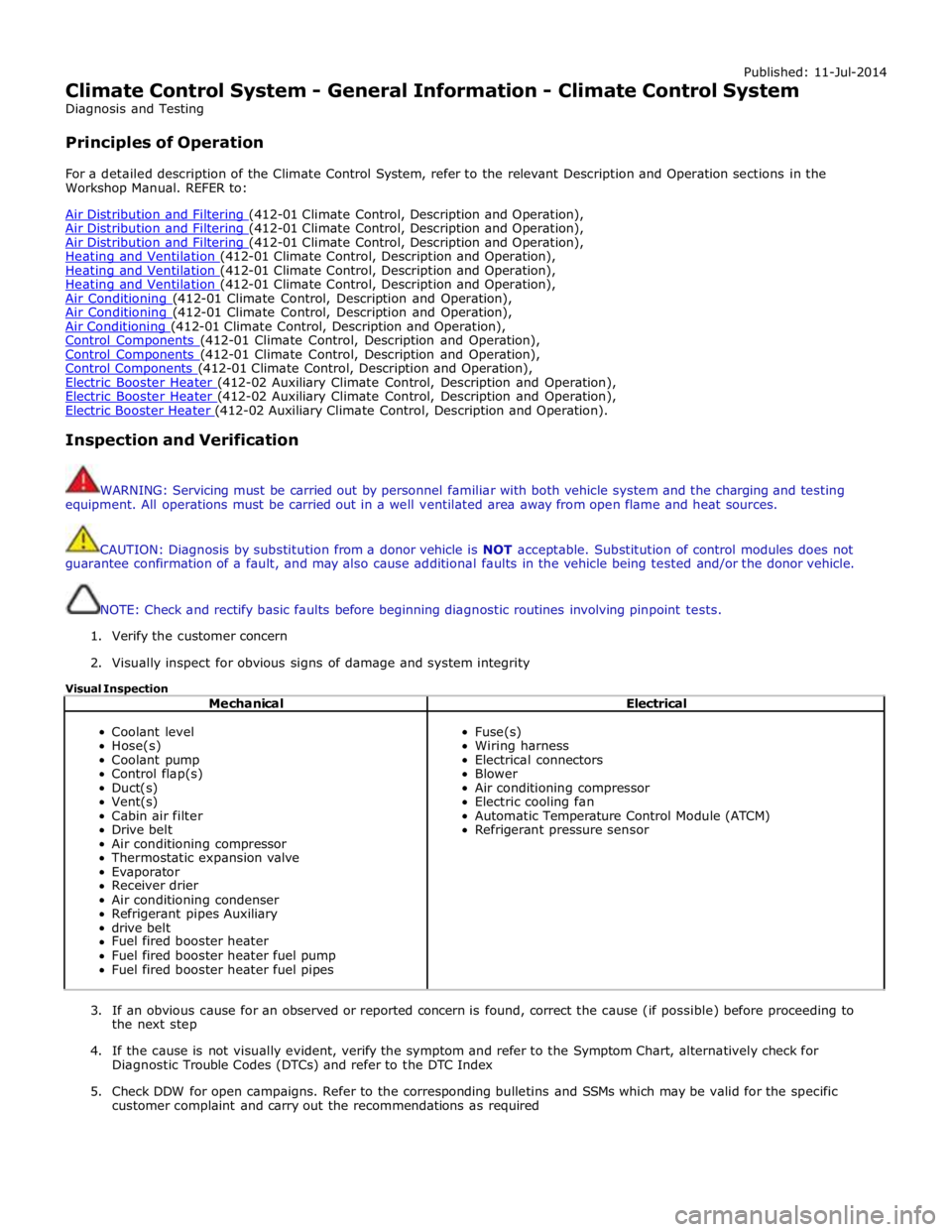
1. Verify the customer concern
2. Visually inspect for obvious signs of damage and system integrity
Visual Inspection
Mechanical Electrical
Coolant level
Hose(s)
Coolant pump
Control flap(s)
Duct(s)
Vent(s)
Cabin air filter
Drive belt
Air conditioning compressor
Thermostatic expansion valve
Evaporator
Receiver drier
Air conditioning condenser
Refrigerant pipes Auxiliary
drive belt
Fuel fired booster heater
Fuel fired booster heater fuel pump
Fuel fired booster heater fuel pipes
Fuse(s)
Wiring harness
Electrical connectors
Blower
Air conditioning compressor
Electric cooling fan
Automatic Temperature Control Module (ATCM)
Refrigerant pressure sensor
3. If an obvious cause for an observed or reported concern is found, correct the cause (if possible) before proceeding to
the next step
4. If the cause is not visually evident, verify the symptom and refer to the Symptom Chart, alternatively check for
Diagnostic Trouble Codes (DTCs) and refer to the DTC Index
5. Check DDW for open campaigns. Refer to the corresponding bulletins and SSMs which may be valid for the specific
customer complaint and carry out the recommendations as required
Page 1699 of 3039
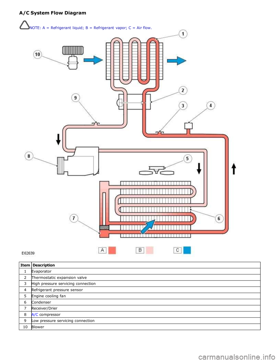
1 Evaporator 2 Thermostatic expansion valve 3 High pressure servicing connection 4 Refrigerant pressure sensor 5 Engine cooling fan 6 Condenser 7 Receiver/Drier 8 A/C compressor 9 Low pressure servicing connection 10 Blower NOTE: A = Refrigerant liquid; B = Refrigerant vapor; C = Air flow.
Page 1709 of 3039
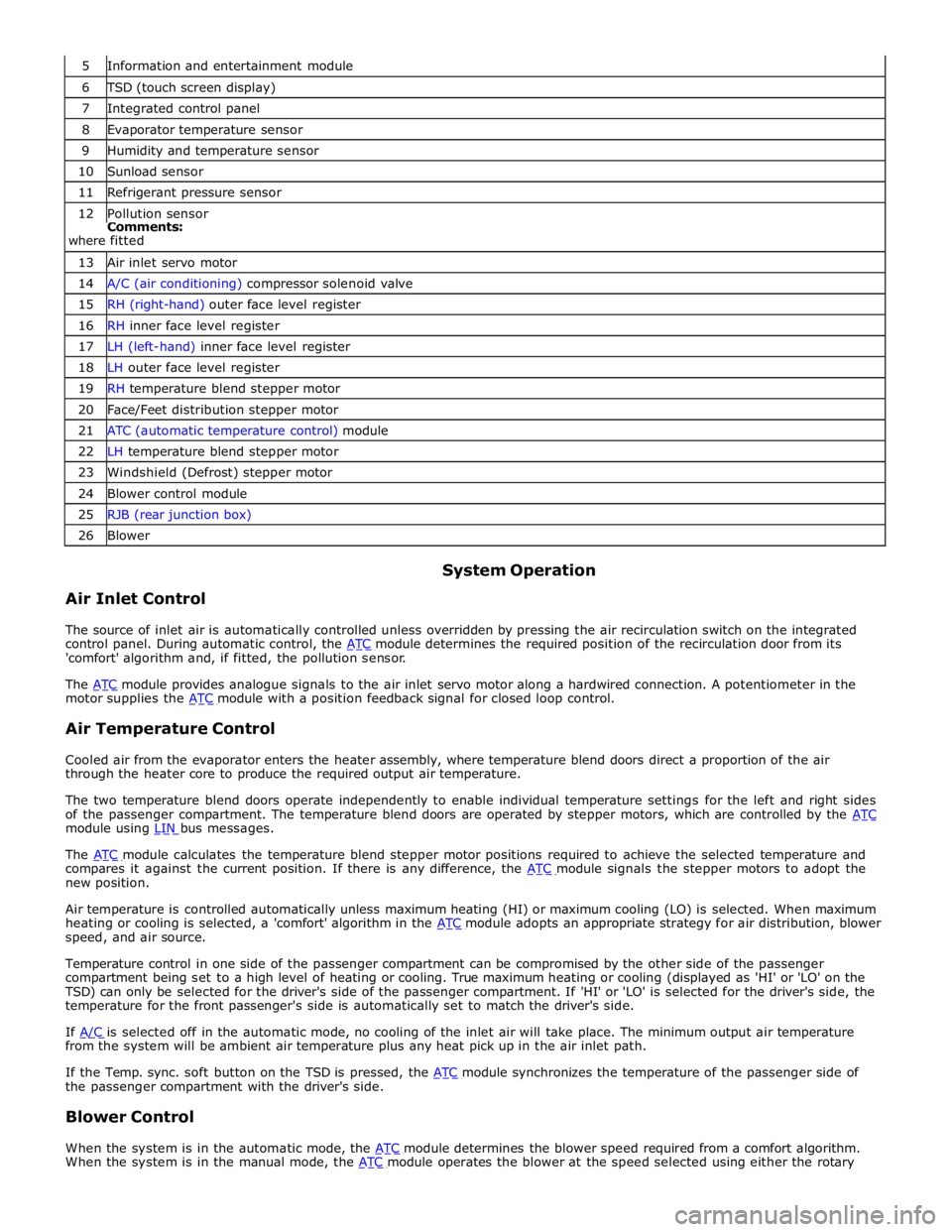
6 TSD (touch screen display) 7 Integrated control panel 8 Evaporator temperature sensor 9 Humidity and temperature sensor 10 Sunload sensor 11 Refrigerant pressure sensor 12 Pollution sensor Comments:
where fitted 13 Air inlet servo motor 14 A/C (air conditioning) compressor solenoid valve 15 RH (right-hand) outer face level register 16 RH inner face level register 17 LH (left-hand) inner face level register 18 LH outer face level register 19 RH temperature blend stepper motor 20 Face/Feet distribution stepper motor 21 ATC (automatic temperature control) module 22 LH temperature blend stepper motor 23 Windshield (Defrost) stepper motor 24 Blower control module 25 RJB (rear junction box) 26 Blower
Air Inlet Control System Operation
The source of inlet air is automatically controlled unless overridden by pressing the air recirculation switch on the integrated
control panel. During automatic control, the ATC module determines the required position of the recirculation door from its 'comfort' algorithm and, if fitted, the pollution sensor.
The ATC module provides analogue signals to the air inlet servo motor along a hardwired connection. A potentiometer in the motor supplies the ATC module with a position feedback signal for closed loop control.
Air Temperature Control
Cooled air from the evaporator enters the heater assembly, where temperature blend doors direct a proportion of the air
through the heater core to produce the required output air temperature.
The two temperature blend doors operate independently to enable individual temperature settings for the left and right sides
of the passenger compartment. The temperature blend doors are operated by stepper motors, which are controlled by the ATC module using LIN bus messages.
The ATC module calculates the temperature blend stepper motor positions required to achieve the selected temperature and compares it against the current position. If there is any difference, the ATC module signals the stepper motors to adopt the new position.
Air temperature is controlled automatically unless maximum heating (HI) or maximum cooling (LO) is selected. When maximum
heating or cooling is selected, a 'comfort' algorithm in the ATC module adopts an appropriate strategy for air distribution, blower speed, and air source.
Temperature control in one side of the passenger compartment can be compromised by the other side of the passenger
compartment being set to a high level of heating or cooling. True maximum heating or cooling (displayed as 'HI' or 'LO' on the
TSD) can only be selected for the driver's side of the passenger compartment. If 'HI' or 'LO' is selected for the driver's side, the
temperature for the front passenger's side is automatically set to match the driver's side.
If A/C is selected off in the automatic mode, no cooling of the inlet air will take place. The minimum output air temperature from the system will be ambient air temperature plus any heat pick up in the air inlet path.
If the Temp. sync. soft button on the TSD is pressed, the ATC module synchronizes the temperature of the passenger side of the passenger compartment with the driver's side.
Blower Control
When the system is in the automatic mode, the ATC module determines the blower speed required from a comfort algorithm. When the system is in the manual mode, the ATC module operates the blower at the speed selected using either the rotary
Page 1710 of 3039
control switch on the integrated control panel or the + and - soft buttons on the touch screen display (TSD). The ATC module also adjusts blower speed to compensate for the ram effect on inlet air produced by forward movement of the vehicle. As
vehicle speed and ram effect increases, blower motor speed is reduced, and vice versa.
Air Distribution Control
Two air distribution doors are used to direct air into the passenger compartment. The doors are operated by stepper motors,
which are controlled by the ATC module using LIN bus messages.
When the A/C system is in automatic mode, the ATC module automatically controls air distribution into the passenger compartment in line with its 'comfort' algorithm. Automatic control is overridden if any of the TSD air distribution soft buttons
are selected. Air distribution in the passenger compartment will remain as selected until the 'Auto' switch is pressed or a
different manual selection is made.
A/C Compressor Control
When A/C is selected the ATC module maintains the evaporator at an operating temperature that varies with the passenger compartment cooling requirements. If the requirement for cooled air decreases, the ATC module raises the evaporator operating temperature by reducing the flow of refrigerant provided by the A/C compressor. The ATC module closely controls the rate of temperature increase to avoid introducing moisture into the passenger compartment.
If the requirement for cooled air increases, the ATC module lowers the evaporator operating temperature by increasing the flow of refrigerant provided by the A/C compressor.
When A/C is off, the compressor current signal supplied by the ATC module holds the A/C compressor solenoid valve in the minimum flow position, effectively switching off the A/C function.
The ATC module incorporates limits for the operating pressure of the refrigerant system. If the system approaches the high pressure limit, the compressor current signal is progressively reduced until the system pressure decreases. If the system falls
below the low pressure limit, the compressor current signal is held at its lowest setting so that the A/C compressor is maintained at its minimum stroke. This avoids depletion of the lubricant from the A/C compressor.
A/C Compressor Torque
The ATC module transmits refrigerant pressure and A/C compressor current values to the ECM (engine control module) over the medium speed then high speed CAN bus, using the CJB as a gateway. The ECM uses these values to calculate the torque being used to drive the A/C compressor. The ECM compares the calculated value with its allowable value and if necessary forces the ATC module to inhibit the A/C compressor by transmitting the 'ACClutchInhibit' CAN message. This forces the ATC module to reduce the drive current to the A/C compressor solenoid valve, which reduces refrigerant flow. This in turn reduces the torque required to drive the A/C compressor.
By reducing the maximum A/C compressor torque, the ECM is able to reduce the load on the engine when it needs to maintain vehicle performance or cooling system integrity.
Cooling Fan Control
The ATC module determines the amount of condenser cooling required from the refrigerant pressure sensor, since there is a direct relationship between the temperature and pressure of the refrigerant. The cooling requirement is broadcast to the ECM on the medium speed CAN bus. The ECM then controls the temperature of the condenser using the cooling fan.
Programmed Defrost
The programmed defrost DEF switch is located on the integrated control panel. When the switch is pressed, the ATC module instigates the programmed defrost function. When selected, the ATC module configures the system as follows:
Automatic mode off.
A/C on. Selected temperature unchanged.
Air inlet set to fresh air.
Air distribution set to windshield.
Blower speed set to level 6.
Windshield heater (where fitted) and rear window heater on.
The programmed defrost function can be cancelled by one of the following:
Selecting any air distribution switch on the TSD.
Pressing the AUTO switch on the integrated control panel.
A second press of the DEF button.
Switching the ignition OFF.
The blower speed can be adjusted without terminating the programmed defrost function.
Rear Window Heater
Rear window heater operation is only enabled when the engine is running. The ATC module controls operation of the rear window heater using a relay in the RJB. When rear window heater operation is required, the ATC module broadcasts a message to the RJB on the medium speed CAN bus. On receipt of the message, the RJB energizes the relay by providing a ground path for the relay coil. This allows a battery feed to flow across the relay to power the rear window heater element.
Page 2315 of 3039
7 Front seat climate control module 8 Passenger seat squab climate module 9 Drivers seat cushion climate module 10 Passenger seat cushion climate module 11 Drivers seat squab climate module 12 Passenger seat cushion heater element 13 Passenger seat squab heater element 14 Drivers seat cushion heater element 15 Drivers seat squab heater element 16 CJB
HEATED SEATS - OPERATION
Heated Front Seats System Operation
The TSD receives a fused power supply from the RJB. One of the 3 seat heat temperature selections made by the driver or passenger using the TSD soft keys are passed from the TSD on the MOST ring to the Information and Entertainment module.
The information and entertainment module processes the information and transmits the request on the medium speed CAN bus to the ATC module.
The cushion heaters have a thermal sensor which supplies a feed back signal back to the CJB. The squab heater elements do not have a thermal sensor and are maintained at the same temperature as the seat cushion elements.
The ATC module reacts to the driver request information received from the information and entertainment module and requests the CJB to activate the seat heaters. The CJB measures the returned temperature signals from the thermal sensors and relays the temperature signals back to the ATC module. The ATC module then uses the measured seat element temperatures to provide closed-loop control of the heater elements to maintain the temperature at one the 3 heat ranges selected.
NOTE: To prevent excessive battery discharge, the heated front seats will only operate when the engine is running.
Heated and Cooled Front Seats
The TSD receives a fused power supply from the RJB. Selections made by the driver using the TSD soft keys are passed from the TSD on the MOST ring to the Information and Entertainment module. The information and entertainment module processes
the information and transmits the request on the medium speed CAN bus to the front seat climate control module. The front seat climate control module is located beneath the RH (right-hand) front seat, on the floor cross member.
The front seat climate control module receives its power supplies from the CJB. Heating and cooling requests are generated using the soft buttons on the TSD. These requests are transmitted to the information and entertainment module over the
MOST ring. The Information and Entertainment module forwards these requests to the front seat climate control module over
the medium speed CAN bus.
The front seat climate control module supplies power to the two climate modules in each seat. The temperature sensor in each
climate module is monitored by the front seat climate control module which uses the temperature information to control the
Peltier cells accordingly and also the blower fans to distribute the heated or cooled air.
NOTE: To prevent excessive battery discharge, the heated and cooled front seats will only operate when the engine is
running.
Electric Driver's Seat Adjustment - Non-Memory Seats
The CJB supplies 3 power supplies to the driver's seat switchpack. The fused supplies provide power for the seat height and squab recline, the seat slide and seat tilt and the lumbar adjustment respectively. The CJB only provides the power to the driver's seat switch pack when the ignition is on (power mode 6).
For the seat movement motors, when the applicable switch is operated, the power is supplied to the applicable side of the
motor and the ground path is completed to operate the motor in the required direction. To move the motor in the opposite
direction the polarity is reversed.
For the lumbar adjustment, when the switch is operated in the inflate position, power is supplied to the pump motor to inflate
the lumbar support. When the switch is operated in the opposite direction, the power energizes a solenoid which in turn opens
a valve to deflate the lumbar support.
Electric Passenger Seat Adjustment ( 8, 10 and 12 way)
The CJB supplies 3 power supplies to the passenger seat switchpack. The fused supplies provide power for the seat height and squab recline, the seat slide and seat tilt and the head restraint and lumbar adjustment respectively. The CJB only provides the power to the passenger seat switch pack when the ignition is on (power mode 6).
For the seat movement and head restraint motors, when the applicable switch is operated, the power is supplied to the
applicable side of the motor and the ground path is completed to operate the motor in the required direction. To move the
Page 2316 of 3039
supplies provide power for the movement motors in addition to the driver's seat switch pack. Power is only supplied to the
driver's seat module and the driver's seat switch pack when the ignition is on (power mode 6).
The driver's seat switch pack is connected to the driver's seat module by a LIN bus for the seat movement switches. Any selection for seat movement generates a message which is passed via the LIN to the driver's seat module. The seat module processes the request and operates the applicable seat function as required using the power supplies from the CJB.
Each seat motor contains a Hall position sensor. The sensor sends a feedback signal to the driver's seat module. The signal is
used for memory store and memory recall functions.
The lumbar adjustment switch on the driver's seat switch pack is wired direct to the lumbar pump and solenoids. The switch,
when moved to the inflate position for either the upper or lower inflatable cushion cell, provides a power supply to the lumbar
pump and simultaneously activates the applicable inflate solenoid valve. When the switch is released the pump stops and the
solenoid valve closes trapping the air in the inflatable cushion. When the switch is moved to the deflate position for either the
upper or lower inflatable cushion cell, power is supplied to the applicable deflate solenoid valve which opens to allow the air in
the cushion to escape. When the switch is released, the valve is closed and the remaining air in the cushion is retained.
FRONT SEATS - DESCRIPTION Component Description
The table below highlights the features available for each seating option.
Seat Type Non-Heated Heated Heated and Cooled Lumbar Support Memory 8-way Yes Optional No 2-way No 10-way Yes Optional Optional 2-way Optional (Driver's seat only) 12-way No No Yes 4-way No 16-way No No Yes 4-way Yes (Driver's seat only) Seat Heating
The 3-stage heated front seats feature 2 heater elements located in the seat cushion and a single heater element located in
the seat squab. Operation of the heated front seats is controlled by the ATC module via the TSD, information and entertainment control module and the CJB module on vehicles with heated seats. On vehicles with heated and cooled seats the operation is controlled by the TSD, information and entertainment control module and the front seat climate control
module.
The heated and cooled front seats each contain 2 climate modules; one in the cushion, one in the squab. The climate modules
contain 'Peltier' cells which are able to deliver heating and cooling based on a voltage provided by the front seat climate
control module. Each climate module also contains a fan, which blows air over the Peltier cells to distribute heated or cooled
air via liners in the seat cushion and squab. The fan is also controlled by the front seat climate control module. The TSD allows
the driver and passenger to select 3 ranges of heated or cooled ventilation; off, minimum and intermediate. Also, using the
selections on the TSD, the driver and passenger can select between full seat ventilation or squab backrest ventilation only.
Vehicles fitted with the 3-stage heated front seat option also feature a heated steering wheel.
Refer to: Steering Column Switches (211-05 Steering Column Switches, Description and Operation).
Electric Seat Adjustment
Lumbar Support
On 8, 10 and 12 way seats, a 2 way lumbar support is provided which allows the lumbar inflatable cushion to be inflated or
deflated as required. On 16 way seats, a 4 way lumbar support is fitted which comprises two separate cushion cells. The upper
and lower cells can be inflated or deflated individually allowing greater comfort adjustment for the driver and passenger.
The lumbar support comprises an inflatable cushion located in the seat squab, a pump and solenoids. The pump is activated
when the applicable seat switch is moved to the inflate position, inflating the cell(s) in the inflatable cushion. On 8 and 10
way seats, a single solenoid operated valve allows the inflatable cushion to be deflated. On 12 and 16 way seats, 4 solenoid
valves control the inflation and deflation of the upper and lower inflatable cushion cells, allowing each cell to be adjusted
individually.
Seat Motors
The head restraint motor is located in the upper section of each seat squab and is accessible by removal of the seat back. The
motor moves a cradle which is driven in a vertical motion by a rack and pinion arrangement. The cradle has the two head
restraint stems attached to it and therefore raises and lowers the head restraint as the motor moves the cradle. The motor
contains a Hall sensor which supplies positional information to the driver's seat module.
The seat slide motor is an integral component of the seat frame. The motor drives on a gear on a worm drive lead screw which
is integral with the floor rail. The lead screw has a stop at each end to limit the fore and aft seat movement.
Page 2821 of 3039

Lighting, Removal and Installation).
7. Remove the condenser core.
For additional information, refer to: Condenser Core - 2.7L Diesel
(412-03, Removal and Installation) /
Condenser Core - V6 3.0L Petrol (412-03 Air Conditioning, Removal and Installation) /
Condenser Core - 4.2L, Vehicles Without: Supercharger (412-03, Removal
and Installation) /
Condenser Core - 4.2L, Vehicles With: Supercharger (412-03, Removal
and Installation).
8. Remove the radiator.
For additional information, refer to: Radiator (303-03A, Removal and
Installation) /
Radiator (303-03B Engine Cooling - V6 3.0L Petrol, Removal and Installation) /
Radiator - Vehicles With: Supercharger (303-03C, Removal and
Installation) /
Radiator - Vehicles Without: Supercharger (303-03C, Removal and
Installation).
9. Remove the both hood latch panel braces.
10. Remove the cooling fan upper shroud.
11. Remove both crash sensors.
For additional information, refer to: Crash Sensor (501-20B Supplemental Restraint System, Removal and Installation).
12. Remove the both hood latches.
13. Remove the hood safety hook guide.
14. Remove both hood latch panel buffers.
15. Release and lay aside the hood latch panel wiring harness.
16. Remove the old panel.