Page 1138 of 3039

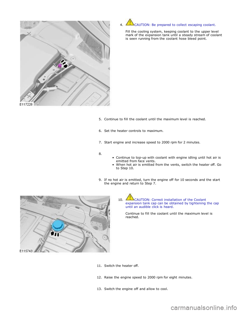
4. CAUTION: Be prepared to collect escaping coolant.
Fill the cooling system, keeping coolant to the upper level
mark of the expansion tank until a steady stream of coolant
is seen running from the coolant hose bleed point.
5. Continue to fill the coolant until the maximum level is reached.
6. Set the heater controls to maximum.
7. Start engine and increase speed to 2000 rpm for 2 minutes.
8.
Continue to top-up with coolant with engine idling until hot air is
emitted from face vents.
When hot air is emitted from the vents, switch the heater off. Go
to Step 10.
9. If no hot air is emitted, turn the engine off for 10 seconds and the start
the engine and return to Step 7.
10. CAUTION: Correct installation of the Coolant
expansion tank cap can be obtained by tightening the cap
until an audible click is heard.
Continue to fill the coolant until the maximum level is
reached.
11. Switch the heater off.
12. Raise the engine speed to 2000 rpm for eight minutes.
13. Switch the engine off and allow to cool.
Page 1167 of 3039
1 Intake manifold assemblies 2 Supply hoses to charge air coolers 3 Charge air radiator 4 Charge air coolant pump 5 Engine cooling system connecting hose 6 Return hoses from charge air coolers
Page 1170 of 3039
1 RH (right hand) charge air cooler 2 Engine 3 LH (left hand) charge air cooler 4 Expansion hose connection (with engine cooling system) 5 Charge air radiator 6 Charge air coolant pump
System Operation
Electrical power for the charge air coolant pump is supplied from the intercooler water pump relay in the power distribution box.
When the intercooler water pump relay is energized, it connects power from the battery, via the BJB (battery junction box)
and CJB (central junction box), to the charge air coolant pump. Operation of the intercooler water pump relay is controlled by
the ECM (engine control module). The intercooler water pump relay is energized continuously while the ignition is in power
mode 6.
When the charge air coolant pump is running, coolant flows from the pump outlet through the charge air coolers, the charge air
radiator and back to the pump inlet. Supercharger Cooling Flow Diagram
Page 1171 of 3039
1 Coolant outlet connection 2 Coolant inlet connection 3 Electrical connector The charge air coolant pump is an electric pump attached to the RH (right-hand) side of the charge air radiator. Hoses connect
the inlet of the charge air coolant pump to the charge air radiator, and the outlet to the charge air coolers. An electrical
connector provides the interface between the motor of the charge air coolant pump and the vehicle wiring. www.JagDocs.com
Page 1172 of 3039

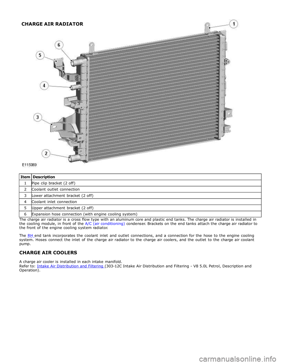
1 Pipe clip bracket (2 off) 2 Coolant outlet connection 3 Lower attachment bracket (2 off) 4 Coolant inlet connection 5 Upper attachment bracket (2 off) 6 Expansion hose connection (with engine cooling system) The charge air radiator is a cross flow type with an aluminum core and plastic end tanks. The charge air radiator is installed in
the cooling module, in front of the A/C (air conditioning) condenser. Brackets on the end tanks attach the charge air radiator to
the front of the engine cooling system radiator.
The RH end tank incorporates the coolant inlet and outlet connections, and a connection for the hose to the engine cooling system. Hoses connect the inlet of the charge air radiator to the charge air coolers, and the outlet to the charge air coolant
pump.
CHARGE AIR COOLERS
A charge air cooler is installed in each intake manifold.
Refer to: Intake Air Distribution and Filtering (303-12C Intake Air Distribution and Filtering - V8 5.0L Petrol, Description and Operation). CHARGE AIR RADIATOR
Page 1363 of 3039

Defaults to base mapping for the ignition timing, with no cylinder correction
Disables the VCT system.
ENGINE COOLANT TEMPERATURE SENSORS
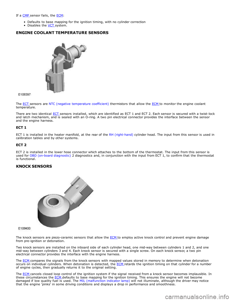
The ECT sensors are NTC (negative temperature coefficient) thermistors that allow the ECM to monitor the engine coolant temperature.
There are two identical ECT sensors installed, which are identified as ECT 1 and ECT 2. Each sensor is secured with a twist-lock and latch mechanism, and is sealed with an O-ring. A two pin electrical connector provides the interface between the sensor
and the engine harness.
ECT 1
ECT 1 is installed in the heater manifold, at the rear of the RH (right-hand) cylinder head. The input from this sensor is used in
calibration tables and by other systems.
ECT 2
ECT 2 is installed in the lower hose connector which attaches to the bottom of the thermostat. The input from this sensor is
used for OBD (on-board diagnostic) 2 diagnostics and, in conjunction with the input from ECT 1, to confirm that the thermostat
is functional.
KNOCK SENSORS
The knock sensors are piezo-ceramic sensors that allow the ECM to employ active knock control and prevent engine damage from pre-ignition or detonation.
Two knock sensors are installed on the inboard side of each cylinder head, one mid-way between cylinders 1 and 2, and one
mid-way between cylinders 3 and 4. Each knock sensor is secured with a single screw. On each knock sensor, a two pin
electrical connector provides the interface with the engine harness.
The ECM compares the signals from the knock sensors with mapped values stored in memory to determine when detonation occurs on individual cylinders. When detonation is detected, the ECM retards the ignition timing on that cylinder for a number of engine cycles, then gradually returns it to the original setting.
The ECM cancels closed loop control of the ignition system if the signal received from a knock sensor becomes implausible. In these circumstances the ECM defaults to base mapping for the ignition timing. This ensures the engine will not become damaged if low quality fuel is used. The MIL (malfunction indicator lamp) will not illuminate, although the driver may notice
that the engine 'pinks' in some driving conditions and displays a drop in performance and smoothness.
Page 1480 of 3039
3. Torque: 5 Nm 4.
5.
Clamp the hoses to minimize coolant loss.
6. CAUTIONS:
Be prepared to collect escaping fluids.
Make sure that all openings are sealed. Use new
blanking caps. www.JagDocs.com
Page 1496 of 3039
Installation
1. Torque: 5 Nm
2.
3.
Clamp the hoses to minimize coolant loss.
4. CAUTIONS:
Be prepared to collect escaping fluids.
Make sure that all openings are sealed. Use new
blanking caps.