Page 1114 of 3039

14 Radiator 15 Auxiliary radiator 16 Connection with supercharger cooling system
System Operation
When the engine is running, the coolant is circulated around the engine cooling system by the coolant pump. From the coolant
pump, coolant flows through the cylinder heads and the engine oil cooler into the cylinder block and the heater manifold.
In the cylinder block, the coolant flows forwards to the outlet tube. When the coolant is cold, the thermostat is closed and the
coolant flows direct from the outlet tube back to the coolant pump. Once the coolant reaches operating temperature the
thermostat begins to open, to control system temperature, and coolant flows from the outlet tube to the coolant pump via the
radiator and, on SC (supercharger) vehicles, the auxiliary radiator. When the thermostat is open, the coolant flow through the
radiator(s) also generates a coolant flow through the transmission fluid cooler.
From the heater manifold the coolant flows through the electronic throttle and the heater core, in parallel circuits that are
unaffected by the position of the thermostat. From the electronic throttle, the coolant merges with bleed coolant from the
coolant pump and the outlet tube and flows to the expansion tank. From the heater core, the coolant flows back to the inlet of
the coolant pump.
Expansion and contraction of the coolant is accommodated by an air space in the expansion tank and the compliance of the
flexible hoses.
If the coolant level in the expansion tank decreases below a predetermined value, the level sensor connects a ground to the
instrument cluster, which activates the appropriate warning. For additional information, refer to 413-01 Instrument Cluster.
The cooling fan is operated by a fan control module integrated into the cooling fan motor. The fan control module regulates the
voltage, and thus speed, of the cooling fan motor in response to a PWM (pulse width modulation) signal from the ECM (engine
control module).
The cooling fan receives a battery feed and an ignition feed from the EJB (engine junction box). The ignition feed is supplied
from the main relay in the EJB, which is controlled by the ECM.
The ECM calculates the required fan speed from the engine temperature, A/C (air conditioning) system pressure and transmission fluid temperature. Under hot operating conditions, the fan may continue to operate for 4 minutes after the engine
has been switched off.
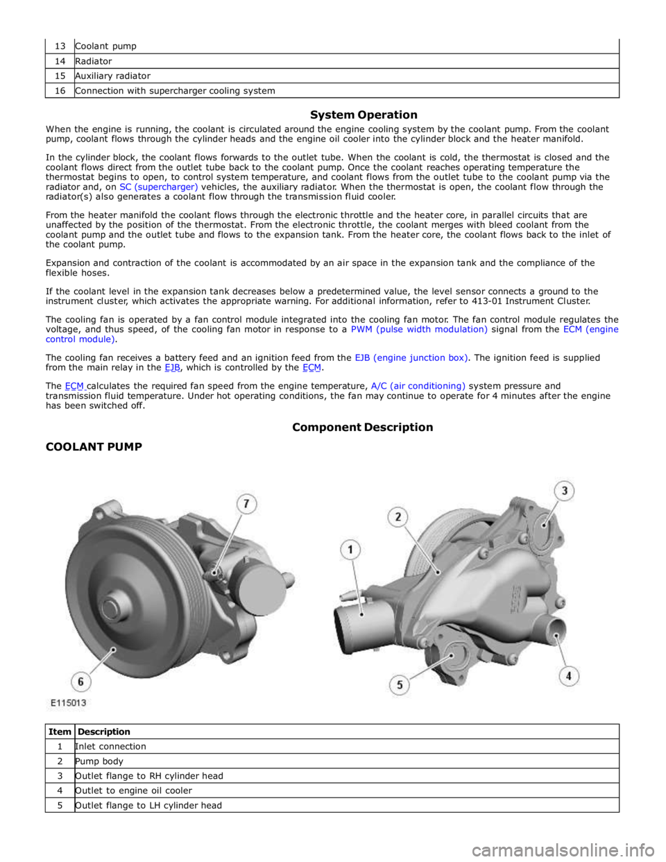
COOLANT PUMP Component Description
Item Description 1 Inlet connection 2 Pump body 3 Outlet flange to RH cylinder head 4 Outlet to engine oil cooler 5 Outlet flange to LH cylinder head
Page 1116 of 3039

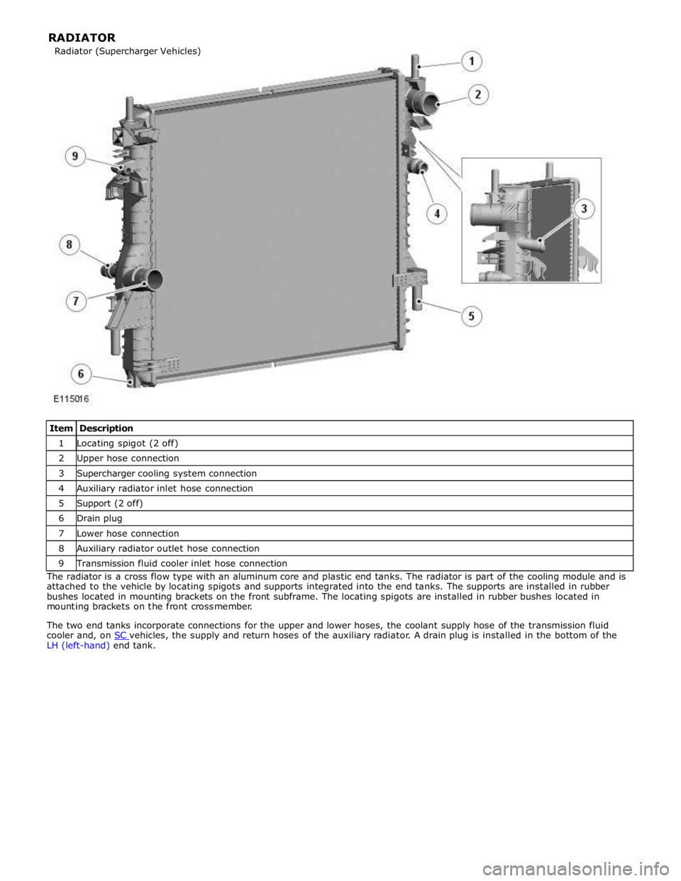
1 Locating spigot (2 off) 2 Upper hose connection 3 Supercharger cooling system connection 4 Auxiliary radiator inlet hose connection 5 Support (2 off) 6 Drain plug 7 Lower hose connection 8 Auxiliary radiator outlet hose connection 9 Transmission fluid cooler inlet hose connection The radiator is a cross flow type with an aluminum core and plastic end tanks. The radiator is part of the cooling module and is
attached to the vehicle by locating spigots and supports integrated into the end tanks. The supports are installed in rubber
bushes located in mounting brackets on the front subframe. The locating spigots are installed in rubber bushes located in
mounting brackets on the front crossmember.
The two end tanks incorporate connections for the upper and lower hoses, the coolant supply hose of the transmission fluid
cooler and, on SC vehicles, the supply and return hoses of the auxiliary radiator. A drain plug is installed in the bottom of the LH (left-hand) end tank. Radiator (Supercharger Vehicles) RADIATOR
Page 1117 of 3039
1 Return hose connection 2 Supply hose connection 3 Bottom bracket 4 Top bracket The auxiliary radiator is connected in parallel with the (main) radiator to increase the engine cooling capacity on SC vehicles. The auxiliary radiator is installed in an air duct, to the right of the cooling module, which takes cooling air from the RH (right-
hand) grille in the front bumper. Two spigots on the top of the auxiliary radiator provide the coolant supply and return
connections with the main radiator.
Page 1119 of 3039
Item Description 1 Filler cap 2 Vent hose connection 3 Expansion hose connection 4 Level sensor The expansion tank is installed in the engine compartment, on the LH upper suspension housing.
A filler cap and level sensor are incorporated into the expansion tank. A MAX level marking is molded into the interior of the
tank below the filler cap. Cold fill levels are molded onto the exterior of the tank.
The expansion tank provides the following functions:
Service fill.
Coolant expansion during warm-up.
Air separation during operation.
System pressurization by the filler cap.
The expansion tank has an air space of approximately 0.5 liter (1.06 US pints), above the MAX level, to allow for coolant
expansion. EXPANSION TANK
Page 1121 of 3039
1 Throttle body heater hose connection 2 Heater core supply hose connection 3 RH cylinder head connection 4 Engine coolant temperature sensor 5 LH cylinder head connection
ENGINE COOLANT
The engine coolant is formulated to last for ten years or 240,000 km (150,000 miles). The coolant is silicate free and must not
be mixed with conventional engine coolant.
ENGINE BLOCK HEATER
Item Description A 110 V ac version B 240 V ac version For vehicle markets subject to very cold climatic conditions, an engine block heater is installed in place of the cylinder block
drain plug. The engine block heater is either a 110 V ac or 240 V ac electric heater element, depending on the market, which
can be connected to a domestic power supply via a connector in the lower center grill of the front bumper. Heater Manifold
Page 1122 of 3039

Published: 17-Apr-2014
Engine Cooling - V8 5.0L Petrol/V8 S/C 5.0L Petrol - Engine Cooling V8 5.0L
Petrol/V8 S/C 5.0L Petrol
Diagnosis and Testing
Principle of Operation
For a detailed description of the engine cooling system and operation, refer to the relevant description and operation section of
the workshop manual. Engine Cooling, Section - 303-03
Inspection and Verification
WARNING: Moving parts can cause severe injury, keep clear of moving parts, never place your hands or any part of your
body near to moving parts
CAUTION: Diagnosis by substitution from a donor vehicle is NOT acceptable. Substitution of control modules does not
guarantee confirmation of a fault and may also cause additional faults in the vehicle being checked and/or the donor vehicle
NOTES:
Check DDW for open campaigns. Refer to the corresponding bulletins and SSMs which may be valid for the specific
customer complaint and carry out the recommendations as required.
If the control module or a component is suspect and the vehicle remains under manufacturer warranty, refer to the
Warranty Policy and Procedures manual, or determine if any prior approval programme is in operation, prior to the installation
of a new module/component.
Check and rectify basic faults before beginning diagnostic routines involving pinpoint tests
1. Verify the customer concern
2. Visually inspect for obvious signs of mechanical or electrical damage
Visual Inspection
Mechanical Electrical
Coolant leaks
Coolant hoses
Coolant expansion tank
Radiator
Heater core
Accessory drive belt
Cooling fan
Fuses
Harnesses
Loose or corroded connector(s)
Engine coolant temperature sensor
3. If an obvious cause for an observed or reported concern is found, correct the cause (if possible) before proceeding to
the next step
4. If the cause is not visually evident, verify the symptom and refer to the symptom chart, alternatively check for
diagnostic trouble codes (DTCs) and refer to the DTC Index
Symptom Chart
Symptom Possible Causes Action Coolant loss
Hoses
Hose connections
Radiator
Water pump
Heater core
Gaskets
Engine casting cracks
Engine block core
plugs Carry out a visual inspection. If there are no obvious leaks, carry out a
cooling system pressure test. Rectify any leaks as necessary Overheating
Low/contaminated
coolant
Thermostat
Cooling fan Check the coolant level and condition. Carry out a cooling system pressure
test. Rectify any leaks as necessary. Check the thermostat and rectify as
necessary. Check the cooling fan operation, make sure the cooling fan
rotates freely. Check for obstructions to the air flow over the radiator.
Rectify as necessary
Page 1128 of 3039

3. CAUTION: Anti-freeze concentration must be maintained at 50%.
Install the cooling system vacuum refill adaptor to the expansion
tank.
Install the vacuum filler gauge to the cooling system vacuum
refill adaptor.
Install the venturi tube assembly to the vacuum filler gauge.
4. NOTES:
Make sure the coolant supply valve is in the closed position on the
vacuum filler gauge assembly.
The coolant vacuum fill tool needs an air pressure of 6 to 8 bar (87
to 116 psi) to operate correctly.
Small diameter or long airlines may restrict airflow to the coolant
vacuum fill tool.
Connect a regulated compressed air supply to the venturi tube
assembly.
5. Position the evacuated air hose into a container.
6. Open the air supply valve.
7. NOTE: Make sure the coolant supply hose is positioned into a container
of fifty percent mixture of Jaguar Premium Cooling System Fluid or
equivalent, meeting Jaguar specification WSS M97B44-D and fifty
percent water. Make sure no air can enter the coolant supply hose.
Open the coolant supply valve for 2 seconds to prime the coolant supply
hose.
8. Apply air pressure progressively until the arrow on the vacuum filler
gauge reaches the green segment.
9. Disconnect the compressed air supply line.
10. NOTE: Close the coolant supply valve when the coolant expansion
tank MAX mark is reached or coolant movement has ceased.
Open the coolant supply valve and allow the coolant to be drawn into
the system.
11. Remove the vacuum filler gauge and cooling system vacuum refill
adaptor assembly.
Page 1131 of 3039
Filling
1. Refer to: Radiator Splash Shield (501-02 Front End Body Panels, Removal and Installation).
2. Lower the vehicle.
3.
4. CAUTION: Anti-freeze concentration must be maintained at 50%.
Fill the cooling system, keeping coolant to the upper level mark of the
expansion tank until a steady stream of coolant is seen running from the
coolant hose bleed point.